Transcription
THE ILLUSTRATION OFLITHIC ARTEFACTS:A GUIDE TODRAWING STONE TOOLSFOR SPECIALIST REPORTSby Hazel Martingell and Alan SavilleLSS OCCASIONAL PAPER No. 3AAI&S TECHNICAL PAPER No. 91988ASSOCIATIONOF ARCHAEOLOGICALILLUSTRATORS& SURVEYORS
THE ILLUSTRATION OFLITHIC ARTEFACTS:A GUIDE TODRAWING STONE TOOLSFOR SPECIALIST REPORTSby Hazel Martingell and Alan SavilleASSOCIATION OF ARCHAEOLOGICALILLUSTRATORS & SURVEYORSTHE LITHIC STUDIES SOCIETYNORTHAMPTON 1988ISBN 0 9513246 0 8ISSN 0950-9208
IntroductionThis booklet, which owes its origins to a series ofnotes first published in Lithics (Martingell 1980, 981,1982, and 1983), is intended to serve as a guide to theillustration of lithic artefacts. It is restricted in focusto types of prehistoric flint and stone tools commonlyfound in Britain, though many of the principlesinvolved will have a much wider application. Thebooklet is aimed primarily at illustrators who are notthemselves lithic specialists but who are in the positionof preparing drawings to accompany specialist lithicreports for publication in archaeological journals andbooks. Such a guidebook seems necessary because therecent growth of interest in lithic studies is leading toan increase in the amount of lithic illustration beingundertaken by more and more illustrators. At thesame time the development of specialist knowledge inthe field of lithics is making greater demands on theillustrator to record ever more detail, often by the useof special conventions and symbols. The experiencedlithic illustrator mayf ind little herein that is new, butit is hoped that the novice illustrator, or the practisingillustrator turning to flint and stone artefacts for thefirst time, will be helped by the following pointsand guidelines. This booklet is also aimed at lithicspecialists themselves, and at non-specialist excavatorsand editors who may be involved in the commissioningof, and in overseeing the publication of, lithic reports.Flint and stone artefacts are usually illustrated in astyle that gives a three-dimensional impression, aform of representation which supplies the maximumamount of information about the technology of anartefact in each single drawing. While the authorswould advocate and seek to encourage the highestpossible standard of illustration, it must be admittedthat the very best examples of the almost fully ‘lifelike’three-dimensional style – for example as achieved inthe woodcut engravings by Swain (in Evans 1897), orin pen-and-ink by Dauvois (1976) – involve a degreeof artistry and commitment which may be beyond theaverage illustrator or at least not cost-effective withinpost-excavation budgets. Constraints on budgetsmay even require at times the production of ‘open’drawings without infilling the details of flake scars.Nevertheless, whatever the style, it is necessary toemphasize the overriding need for accuracy in this asin other aspects of archaeological drawing. A groupof superficially similar implements, such as a seriesof leaf-shaped arrowheads from the same site, willcontain differences of detail which the specialist willneed to see reflected in the illustrations, and whichwill be necessary to enable the reader to comprehendvisually the specialist’s written account. Researchworkers and museum staff will require accurateillustrations to check against the artefacts themselvesor against catalogue notes; all too often either theartefacts or the original records can become mislaid,and then the illustrations are vital in re-establishinga provenance or re-uniting an assemblage. Ideally,illustrations should be an essential part of a catalogueof lithic artefacts, though in this case not all drawingswill necessarily be finished to publication standard.Consistencies of style, of orientation (Fig. 1), ofconventions, etc., are important, as well as accuracy,for conveying the character of a particular assemblageand for creating the all-important visual harmony ofa set of drawings. The specialist will want the lithicillustrations to display the overall impression of thenature of the assemblage being analysed, and goodillustrations in this regard will be far more successfulthan many pages of descriptive text.This guidebook has been kept intentionally brief toreduce costs and increase availability, but is designedto contain enough information for the intendinglithic illustrator to proceed effectively. Those seekingmore detailed and technical guidance and a widerrange of model illustrations should consult the worksby Addington (1986) and Dauvois (1976).Working with the lithic specialistThe best drawings are achieved when there iscollaboration between the illustrator and the lithicspecialist. This sounds obvious, but it is all toocommon for such collaborations to founder underthe pressures of publication deadlines, disagreementsbetween specialists and excavators, and so on.Ideally the illustrator should not begin work onthe illustration of a group of lithic artefacts untilpreliminary notes on the drawings are supplied bythe specialist. Certainly the illustrator should neverprepare publication drawings for an excavator beforea lithic specialist has been engaged - otherwise there isa risk that the illustrations will have to be completelyredrawn or that entirely different artefacts will beselected for illustration.Preliminary notes from the lithic specialist shouldindicate the level of illustration, whether fully detailedor schematic; the orientation of each artefact relativeto an upright page; the number and position of viewsand sections; the position and nature of any specialfeatures such as edge gloss; and the full referencenumber and site code of each object. All drawingsshould be examined by the specialist at the pencilstage, so that if any corrections are necessary they canbe made before inking.Understanding the specialist’s requirements can bedifficult, if not impossible, without some knowledgeof basic lithic technology and typology (Fig. 1).Background reading of introductory texts will help(e.g. Bordaz 1970 and 1971; Pitts 1980; Timms 1974;Watson 1968), but is no substitute for the observationof a demonstration of flint-knapping techniquesby a modern practitioner. Such demonstrationsare increasingly common as a component of dayschools organized by archaeological groups anduniversity extra-mural departments. Familiarity with1
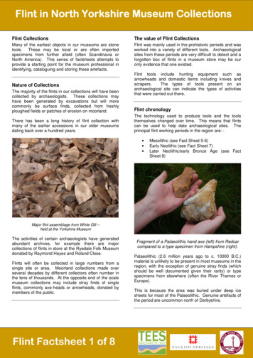
the terminology of flaking used by the specialist such terms as striking platform, bulb of percussion,bulbar scar, faceted butt, etc. (see Fig. 1) - will be veryuseful to the illustrator. There are clear differences inquality between the drawings of those illustrators whounderstand the principles of knapping and those whodo not.Equally, the specialist must be aware of the needsand level of knowledge of the illustrator and of theconstraints under which illustrators often work. Forexample, the specialist may have access to publishedor unpublished work unavailable to the illustrator, andshould supply photocopies of relevant drawings. Norneed communication between specialist and illustratorbe one-way, since feedback from the illustrator canoften improve the specialist’s understanding of detailson a particular artefact.outer surface of a stone pebble may remain on someartefacts, and are usually represented by stippling (seeFig. 2). To be able to indicate the humanly struckareas on worked flint, which are normally apparentas negative flake beds or scars, it is essential tounderstand the direction of each flake removal. Flintfractures conchoidally, that is in a manner resemblingthe curved, concentrically ribbed surface of someshells. In other words, from the point of impact orpercussion where the hammer strikes the flint surface,a series of concentric ripples are formed which areoften visible both on the bulbar surface of the struckflake and on the negative flake scar left on the coreor implement being worked. These ripples must berecorded to indicate the direction of flaking involved,and are usually drawn in continuous curved lines, thebest effect being obtained with a split-nib pen thatallows a variable line thickness (Fig. 3).Some implements, like piercers, may comprisesimple flakes on which little or no readily visiblemodification has taken place, while in other cases - abarbed-and-tanged arrowhead for example - a flakemay be very elaborately retouched into the requiredform. Such elaborate retouch or secondary workingmay involve very small, precise flake removals, forwhich it is important to record the exact directionof flaking. With some implement types, such as endReading the artefactA single lithic artefact may have several differenttypes of surface area visible, each requiring separatestylistic treatment. For example, there may be naturalfractures resulting from burning or freeze-thawclimatic conditions, which must be distinguished onthe drawing from humanly produced facets. Areas ofthe outer skin (cortex) of a flint nodule or the smoothFig. 1A selection of outline drawings to indicate points of artefact typology, terminology and orientation. Not to scale.2
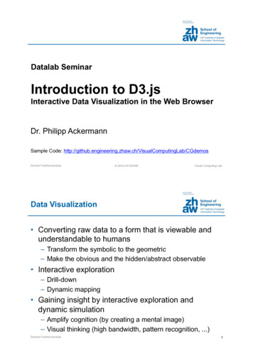
Fig. 2Flint flake showing the contrasting depiction of natural features and humanly-produced effects.Drawn at 1:1 for reproduction at 1:1scrapers, the direction of retouch at the scraping edgewill probably be apparent even on a poor illustration,but for more complex implements or cores the carefuldistinguishing of the direction of flake removals iscrucial.an implement will be complete, as the drawing willreveal by the presence of a negative bulb of percussion.Previous flake scars will be truncated to a lesser orgreater extent (Fig. 4). The way in which flake scarsare truncated and shaded will indicate the order offlake removals (Fig. 5) and a successful drawing willallow the flaking ‘history’ of an artefact to be read.When an artefact becomes ‘rolled’, normally bythe natural friction created by movement in wateror gravel for long periods, it loses the sharpness ofthe ridges between flake scars and flake faces whichis a feature of freshly struck pieces. These bluntedand blurred features must be faithfully reflected inThe flake ripples will not always be readily apparent(though they may ‘emerge’ under magnification or byholding the piece of flint sideways to a light source)and it is often necessary to indicate them somewhatschematically. Cracks and crystal pockets whichoccur naturally in flint should be shown realisticallywherever possible, as these faults can cause a changein direction of flake ripples, and their inclusion canexplain the presence of an irregular flake scar. If suchfaults are profuse, however, a balance must be kept inthe drawing to avoid obscuring the details of flakingand retouch.As important as the direction of flake removals isthe sequence in which those removals have taken placeon an artefact. The most recent negative flake scar onFig. 4 Complete and truncated flake scars: a) complete scar withprogression of ripples from very curved at the base to shallow at thetop; b) scar with bulbar end removed leaving an area of shallowripples; c) scar with distal end removed leaving the curved ripplesin the area of the negative bulb; d) scar truncated longitudinally.Original drawing reduced by 50%.the drawing when ‘rolled’ artefacts are illustrated,normally by leaving open the intersection of the flakescars (Figs. 9 and 18), or by depicting the intersectionas a dashed or stippled line rather than a solid one.All lithic flake tools have an under surface (bulbaror ventral) and an upper surface (dorsal). Normallyonly the dorsal surface is illustrated, together with aside view or a cross-section or profile. This is becausethe secondary working or retouch is most frequentlyFig. 3Types of line used for infilling flake detail according toraw material and surface condition. The broken and jagged lineswould be used on stone rather than flint, to suggest the coarserquality and uneven surfaces.Printed at the scale at which drawn.3
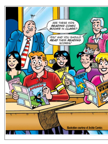
Fig. 5 A fragmentary pick (flint) used as an example of the analysis of the order of flake removals. The flatter, ventral surface (view I) wasprobably the first to be flaked and the numbers 1-11 show the possible order of removals, with 0 being the only remainder of the originalbulbar surface. It can be seen that flake scars 1-11 are all truncated at their proximal ends, lacking negative bulbs of percussion. Thistruncation was caused by the four main steep removals from the dorsal surface (view 2a). The sequence of these large scars on the dorsalsurface can be determined since flake scar B invades A and therefore postdates it, similarly scar D postdates C. Flake scar X, struck from theextremity of the implement, predates removals B, C, and D, each of which truncates it. The final stage of flaking involved the removal ofsmall trimming flakes along the edges of the ventral surface (view 3), and these retain their negative bulbs of percussion. The publicationdrawing of this implement would comprise views 2a and 2b, views 1 and 3 being included here only to demonstrate the kind of analysiswhich would take place in the mind of the illustrator during the process of drawing the implement. Despite the overall similarity in the wayin which the flake scars are depicted in views 2a and 2b, it is still possible to determine the sequence of flake removals from the drawing,showing that the illustrator has understood the way in which the implement has been flaked, thus in turn allowing the flaking history to belegible to the viewer. Drawn at 1:1 for reproduction at 2:3.restricted to the dorsal surface, while the ventralsurface simply comprises a single, positive, flakesurface. The same applies to totally unretouchedpieces, since the chief interest of the artefact probablywill lie in the pattern of negative flake scars formingthe dorsal surface.Side views and profiles are placed directlyalongside the dorsal view. There has in the past beenconsiderable variation in which side of the artefact theaccompanying side view has been placed against, andin which direction it was shown to face. Such variationbecomes extremely confusing if there is inconsistencywithin a given set of drawings. (For an example ofthis kind of inconsistency see Saville 1981a, wherethe use of variable positioning by different illustratorshas created an odd effect once the drawings have beenmounted together.) In fact, unless a standardizedprocedure for positioning views is employed, thereader can never be entirely sure which side view iswhich. It is recommended here, therefore, that the socalled ‘American projection’ of aspect conventions, asshown in Fig. 6, is followed in all cases. Any deviationfrom this system should be carefully labelled to showwhich view is being depicted.Vertical cross-sections are placed to the right of thedorsal w, and centrally between the dorsal and ventralviews if both are drawn. Horizontal cross-sections canbe placed above, below, or to the side of the dorsal viewaccording to where they fit best in a particular instance.The cross-section of a particular part of an implement,such as the tip of a piercer (Fig. 22), should be placedalongside the position of the section, with link-lines ifnecessary to make the relationship clear.The colour of an artefact, where relevant, isdescribed in the text and not by the illustration.Fig. 6The aspect conventions for illustrating various views ofthe same artefact. This system, know as orthographic or Americanprojection, requires each new view to have the same surfacesadjacent. If the artefact were a flake, then A would be the dorsalsurface and B the bulbar one.4
The same is normally true of variations in surfacecolour occurring on a single artefact; in the case offlint artefacts such variation will usually be postdepositional and of no significance for the originalmanufacture and use of an implement. Colourbanding or variegation on stone implements, wherethis is thought to relate to the original selection ofraw material, may need to be depicted (e.g. Roe1968, fig. 36a), but can also be achieved inexpensivelyby publication of a monochrome photograph tocomplement a drawing (e.g. Roe 1985, figs. 8-9).reference to normal conventions (see below), thefollowing sequence of drawing stages may be adopted.1. Place the artefact flat on the drawing surface(whether plain paper, graph-paper, or tracing- paperor drawing-film over graph-paper), if necessarysteadying it with a wedge of ‘Blu-tack’. Avoid unduepressure on delicate flint artefacts when using ‘Blutack’; longitudinally curved pieces can easily snapwhen pressed against the hard surface of a drawingboard.2. With the lead of a pencil held perpendicularto the drawing surface and vertically positionedagainst the side of the artefact, draw carefully aroundthe edge to achieve the outline (Fig. 7a). Beforecontinuing, check the outline by holding a setsquare upright against various positions around theartefact’s perimeter. Take care to avoid damaging theedges of delicate artefacts with the lead of the pencil;if necessary use a series of dots on the paper to keyin the main features of the outline, determining theirposition with an .upright set-square set against theedge of the artefact, then join up the dots by eye.3. Key in on the drawing the junctions of the mainflake removals on the surface to be illustrated at thepoint where they intersect the outline (Fig. 7b), againusing a set-square if necessary.4. Place a sheet of rigid perspex (or glass) overthe artefact, supporting it on suitable props to bringit flush with the surface of the artefact and parallelto the surface of the board. Trace the inner ridgesbetween the flake scars and any other surface details,either directly on to the perspex, or on to acetatedrawing film taped to its surface (Fig. 7c). The tracingmay be easier if the surface details of the artefactPractical IllustrationLithic artefacts are normally drawn at actual size(1:1), except in the case of very small implements,like some microliths, which may be drawn at twicelifesize (2:1). The subject of reduction is discussedfurther in a following section. It should be notedthat there is a school of thought which advocates thedrawing of almost all lithic artefacts at twice lifesize,to permit easier depiction of finer detail and to allowsubstantial reduction to publication size to ‘crispen’the image. This practice has been the rule in thearchaeological drawing-office of the Department ofthe Environment (now English Heritage) at FortressHouse, from where many influential illustrations haveemanated (e.g. drawings of flint artefacts in Saville1981a and Wainwright 1979). The technique relieson the availability of mechanical visualisers, however,without which the production of numerous enlargeddrawings is too time-consuming to be practical.Assuming the artefact is to be drawn at actualsize, and assuming that the orientation has beendetermined from the specialist’s instructions or byFig. 7Stages in the illustration of the dorsalsurface of a flake (see text for details).5
have previously been highlighted by running a softpencil directly along the flake ridges, etc. (Such marksshould be removed before returning the artefact to thespecialist!)5. Transfer the internal details on to the paperwith the outline (Fig. 7d), using a light-box ifnecessary. This stage can be avoided by using the sametransparent sheet for the outline and the tracing.Note that not every illustrator will choose to usethe perspex sheet technique, developed by one of us(H.M.) as a rapid method for producing accuratedrawings. The technique is perhaps most useful onpieces with complex retouch or where there is a lotof depth to be compressed into the horizontal plane.Other illustrators prefer to measure numerous keyrelationships, sometimes using a compass to plotridge junctions by intersecting arcs, while experiencedillustrators often work mainly by eye: see Addington(1986, 56).6. Check any doubtful relationships between thesurface details by measuring from object to drawingusing dividers, callipers, or slide-gauge. Remember toallow for the effect of perspective when dealing withartefacts which have a surface exhibiting substantialvertical variation.7. Continue the drawing by adding the rippleswithin the scars, and any other areas of retouch,fine secondary working, cortex, etc., working by eyefrom object to drawing and using dividers etc. wherenecessary (Fig. 7d). It is conventional to assume,when shading, that objects are illuminated fromthe top left-hand corner of the page; it will help tolight the artefact in this way while composing theillustration. This lighting convention has two majorimplications, firstly, for the implement as a whole,principal light areas will be on the top left-handsurface of the object, and all the shadows will buildup on the lower right-hand areas; secondly, for eachindividual flake scar, the darker, more shadowy zonewill be immediately below the ridge at the upper orleft edge of the scar, depending on the orientation ofthe scar and its relative depth. To repeat this light-toshade effect on the illustration it will be necessary tobegin the shading/ripple lines filling in the surfaces ofthe negative flake scars with the thick end of the linestarting from the ridge between two scars, and then‘feathering’ this line off to fade over the light areas.Lines are drawn closer together across areas in shadowand further apart on lighter surfaces. Cross-hatchingshould be avoided. It usually looks better if wider,flatter arcs are used for the ripple lines furthest fromthe point of impact or the edge of the artefact.8. If a ventral (or bulbar) view is also required, theoutline can be obtained by tracing from the drawingof the dorsal view on to transparent paper/film, thenreversing this and drawing the internal d:etail of theventral view on the other side of the sheet.9. The initial stage of drawing a side view is toestablish on the paper/film an accurate rectangle withinwhich the view must fit. The top and bottom lines ofthe rectangle are obtained by extending sideways thedimensions of the dorsal view or by tracing from it.The former is easily done if using a graph base forthe drawing; if using paper then parallel lines can beprojected using a set-square. The sides of the rectangleare obtained by measuring the maximum thicknessof a symmetrical artefact, or the maximum verticalheight of an assymetrical artefact when laid flat in thesame position assumed for the dorsal drawing. Theartefact can then be set on edge within the rectangleusing ‘Blu-tack’ and the perimeter drawn around torecord the outline. Especial care must be taken tocheck the accuracy of the side view outline with a setsquare because of the optical distortion when viewinga deep object in this manner. The positions of thejunctions of the flake scar ridges can then be keyedin from the dorsal view drawing, either by tracing orby extending parallel lines. If the ventral view is beingdrawn as well as the dorsal one, then the side viewshould be left until last so that ridge junctions canbe keyed in from both of the face views. The rest ofthe ridge pattern on the side view can then be drawnusing the perspex sheet technique or by measurementand reference to the face views. 10. When the pencildrawing is complete, with the identification numberof the object clearly marked, it should be checked bythe lithic specialist. (If illustrator and specialist areliaising at a distance then good quality photocopiesof the drawings should be sent in the post -not theoriginals!) Any necessary alterations should then bemade in pencil and the drawing given a further checkbefore being carefully inked over. It will be a matterfor arrangement between individual illustrators andspecialists as to how much ancillary detail, such ascomplete shading, cortex stippling, etc., is necessary atthe pencil stage. 11. In the final inking it is importantnot to lose any information from the pencil drawingby inaccurate or over-thick pen work. Always have ithe actual artefact to hand when the inking is done;inking up in the absence of the artefact leads to ‘flat’,mechanical-looking drawings. Keep the surface ofthe ink drawing clean and free of ‘grease’ by workingwith a sheet of paper between the drawing hand andthe drawing surface. In an attempt to render moresympathetically the texture of some flaked artefacts,particularly those of stone rather than flint, somespecialists have opted to reproduce pencil rather thanink drawings in their final illustrations (e.g. drawingsby P. O’Leary in Green 1984, 121-145). This hasmuch to commend it, but does present technicaldifficulties in printing which can result in less, ratherthan more, detail appearing on the published page.Pencil drawings are also more vulnerable than inkedones to accidental erasure. 12. Lines linking thedifferent views of the same artefact must be included.These should be short, horizontal lines, parallel to thebase of the page, drawn with the rule, not free-hand.Link-lines (also known as connecting lines) are usuallypositioned at or near to the base of the illustratedartefact. Pairs of shorter horizontal lines, placed either6
side of the artefact at the appropriate point, are usedto indicate the position of cross-sections. The use ofadditional link-lines, sometimes dashed, to relate to itslocation on the artefact a special view such as a facetedbutt (Fig. 1, no. 10) or a core platform (Fig. 16), or apartial view such as an overhung retouched edge (Fig.22), are optional, depending on the ‘readability’ of theoverall illustration. When illustrating broken artefactsthe break-edges should always be indicated by shortcontinuation lines (also known as break-lines) at eachside of the break, again drawn with a rule. Resist thetemptation to reconstruct the shape of the missingarea with a dashed line; such reconstruction on paperwill be required by the specialist only in exceptionalcases.13. Cross-sections may be left open (e.g. Fig.15), filled-in with oblique lines (e.g. Fig. 5), or canbe fully blacked-in (e.g. Fig. 19), though the latteris inadvisable if the cross-sections are thick and/or numerous on the page, as too much solid blackproduces an unbalanced effect, which distractsattention away from the main views to the sections.Profile views designed to indicate the basic side aspectof an artefact are usually left open, except for a singleline indicating the junction of the ventral and dorsalfaces (e.g. Fig. 8), and it is the presence of this linewhich distinguishes a profile view from an open crosssection.14. The numbering or labelling of the illustratedlithic artefacts on the drawing ideally should be theresponsibility of the illustrator, not the specialist orthe editor. Rub-down lettering (such as ‘Letraset’) isnormally preferable to the use of stencils. Rememberto ‘fix’ applied lettering with the appropriate spray orit may become damaged by the time the illustrationsreach the printing stage. This should be done as theabsolutely last stage, however, when nothing elseneeds adding or altering.15. Finally a scale is essential on each page ofdrawings to avoid any confusions caused by reductionerrors or incorrect captions. The scale should be keptas simple and unobtrusive as possible and should bemetric only.16. The question of whether or not the illustrator’sname or initials should be added to a page of drawingsis a vexed one. One of the most famous and talentedof all lithic illustrators, Pierre Laurent, regularlyadded his name in freehand around the base of anartefact drawing and this was frequently reproducedin publication (e.g. Bordes 1981). Laurent’s practicein this matter has been followed by Addington(1986). On the whole the present writers prefer theattribution to be left out of the field of illustration,as long as the authorship of the drawings is clearlyacknowledged in the caption or elsewhere in the text.Fig. 8Palaeolithic handaxe or biface (flint). As can be seen from the profile, the dorsal surface is domed while the ventral surface ismuch flatter: this is reflected in the differential shading of the flake scars on either face. One of the scars on the dorsal surface has a fault line(A) where the pattern of ripples has been interrupted, and this is shown in negative rather than by a solid line, which would confuse thescar pattern. On the ventral surface small patches of coarser material within the flint matrix are visible and have been shown by stipple. Theconchoidal fracture pattern is not clear at these points (eg at B) and the scar ridges and surface ripples are therefore not shown.Drawn at 1:1 for reproduction at 2:37
If such an acknowledgement cannot be guaranteedthen there are grounds for adding an attribution,but this must not detract from the artefact drawingsthemselves.accurately. Small areas of polish, where for examplejust the cutting edge of an axe has been polished, canbe left open (Fig. 11) or shown in solid black, whichis also often suitable for the polished areas of flakesor fragments from polished implements. (See Curwen1939, figs. 1-3, for some fine examples of illustrationsby Robert Gurd using solid black for areas of polish,as well as stipple to depict lustre.)2. Burins (or gravers)(Fig. 1, nos. 14-15 and Fig. 12)These tools have chisel-like angular edges formedby the removal of the so-called burin-spall (or spalls).The burin facet (negative flake scar) left by the removalof the spall is normally drawn in detail, sometimesentailing partial or complete side views, and isalso indicated by the convention of a small arrow.The arrow is placed at the bulbar end of the facet,pointing down its length. If the burin edge is formedby more than one removal this will be indicated bythe commensurate number of arrows, and where itis possible to determine the most recent removal, thearrow for that spall can have a filled circle symbolattached. Burins are normally flake tools and arepositioned with the bulbar end of the blank towardsthe bottom of the page.3. Backed blades or f
in pen-and-ink by Dauvois (1976) – involve a degree of artistry and commitment which may be beyond the average illustrator or at least not cost-effective within post-excavation budgets. Constraints on budgets may even require at times the production of ‘ope