Transcription
PDHonline Course E367 (2 PDH)Designing to Lightning Standard, NFPA-780-2011Instructor: Thomas Mason, P.E.2012PDH Online PDH Center5272 Meadow Estates DriveFairfax, VA 22030-6658Phone & Fax: 703-988-0088www.PDHonline.orgwww.PDHcenter.comAn Approved Continuing Education Provider
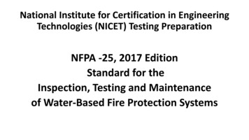
www.PDHcenter.comPDH Course E367www.PDHonline.orgDesigning to Lightning Standard, NFPA 780-2011Thomas Mason, PEThe goal of this course is to learn how to design lightning protection systems. Fortunately, it is veryeasy. Please consider the following four examples:This illustration is for orientation.This illustration identifies the components and introduces the basic rules for an NFPA 780-2011lightning protection system. To the left are the air terminals, conductors, supports, and ground rods.To the right are electric power service components which are essential to lightning protection. If theydo not already exist, they must be added at the time of lightning rod installation. Note especially theintersystem bonding terminal and surge protective device (SPD). The equilization bonding conductoris part of the lightning protection system. IEEE says that you must place an additonal surge protectivedevice at each critical, sensitive equipment, such as television, personal computer and microwave. Thomas MasonPage 2 of 18
www.PDHcenter.comPDH Course E367www.PDHonline.orgWhy is this course organized this way and what is this box and who cares about IEEE ?First, the box.This course contains hard content, as materials requirements, minimum and maximumdimensions, counts and spacing. It also contains asides, interesting useful information that is notcentral to complying with the Standard. Such asides will be placed in boxes like this, calledsidebars, to offer the opportunity to skip them completely, if you wish.Now, regarding the examples.To convince you that this course provides immediate value in your job, we are giving examplesof the product we promise to deliver. If you wanted to learn to do calculations or fill outrequirements forms, this is the wrong course. We will refer to our examples to show how toapply the hard content.Regarding additional surge protective devices and IEEE recommendations. NFPA 780 requires asurge protective device (SPD) at the electric power service. It recommends additionaldownstream SPD at branch panels (commercial and industrial) and at critical sensitiveequipment. The IEEE Emerald Book, dedicated to protecting equipment from surges, requiresSPD at the critical, sensitive device and recommends upstream SPD at the branch panel and atthe service.If your goal is to protect the structure and its contents, do put in more than the minimum SPD.(And that does not mean you should buy a premium single unit. It means you should buymultiple good units.)Referring to the illustration, Ridge Protection, Less than 75-ft, Corner Downcomer, let us examine eachdetail. First, the title, Ridge Protection. We normally think of lightning as coming down from the sky,so the highest point on the structure has the most exposure. And, normally this is correct. The ridge isthe line along the top of the roof, sticking up highest into the sky. This is correct placement only asfirst approximation.There is a very common circumstance in which a storm front rapidly approaches. You can see theclouds coming at you. Sometimes, you can see an actual edge of the rain approach. What you don’tsee is the change is the electric charge coming at you. This is easily measurable, using high schoolphysics laboratory equipment (gold leaf electrometer or electronic equivalent). As the charge frontapproaches, it is common to get a side flash to the gutters of a building or to the extended branches of atree.The intuitive approach would say, “That is only a few moments in a thunderstorm that can last forhours or days. It can’t be much of a statistical hazard.” Wrong. Just driving around, you can see thesoot, damaged masonry and crispy branches, usually about midway up the tree, with a clear path to themain stalk and down to the trunk.Ridge protection is the first line of defense, but perimeter protection is a close follow-up, and thenormal protection for commercial and industrial structures.Back to the illustration. Less than 75-ft distinguishes tall structures from short structures, within the Thomas MasonPage 3 of 18
www.PDHcenter.comPDH Course E367www.PDHonline.orgdefinition by NFPA. There are three differences between less than 75-ft and more than 75-ft, asfollows:NFPA 780‐2011ItemNameAir TerminalMain /DowncomerEarthingLess than 75‐ftClass Imin 3/8‐in dia57 kcmil(between #2and #3 AWG)More than 75‐ftClass IImin 1/2‐in dia115 kcmil(between 1/0and 2/0)RodsRods and LoopCorner Downcomer introduces two critical concepts - earth potential and current dissipation. Earthpotential is the voltmeter reading between where you are measuring and remote earth. It is nonintuitive, but the local value of ground changes by several hundred volts as a storm approaches andpasses over.Why do you say that local ground value changes ?I could cite publications, but I would rather cite personal experience. In the 1980’s I was techsupport for a large petrochemical research facility. As we kept building more laboratories, wekept extending our RS-232 data network (the best available at that time). When the runsexceeded 500-lf, we started blowing RS-232 receiver chips.RS-232 is defined as 12, -5 V pulses, 1200bps to 56kbps (personal computers use 5, 0 V, butthat is another story). The OEM receiver chips were rated to 50 V input. After many, manyfailures of these chips, we found a 300 V input chip that was a pin-for-pin replacement. Today,we would use opto-isolators and surge protective devices.As part of troubleshooting the RS-232 problem, I lifted ground leads and saw them spark andmeasured 50-100VDC with a digital meter, but 0VDC with a Simpson analog meter. It was highvoltage with tiny current. On the other hand, I have seen the #22 AWG ground wires burned off,probably associated with a nearby strike rather than a ground shift.Current dissipation is what happens when the lightning rods does its duty. A current of 50,000 –500,000A (short duration) will travel across the main, use the downcomer and ground rod. From theground rod, it dissipates into the contacting earth. This subject has been extensively researched forhigh-voltage electric substation faults. Those longer duration current flows create a lethal voltage, orstep potential at the point of entry to the earth, which diminishes exponentially as you move away fromthe point of entry.For lightning current dissipation, the massive current flow boils the moisture at the rod and it expandsaway from the rod. The earth adjacent to the rod is now dry and non-conductive.Between the two, differing ground potentials and no-longer-functional ground rods, you can see why itis required to have a minimum of two ground rods and they should be placed as far from each other aspossible. Thomas MasonPage 4 of 18
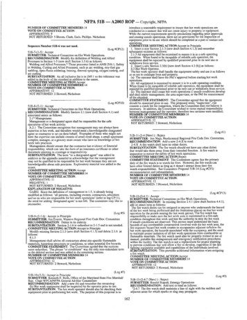
www.PDHcenter.comPDH Course E367www.PDHonline.orgBut not far from the building. The ideal position of the ground rod is at the downcomer, 24-30-in fromthe foundation. More distance is bad. Lightning is very quirky. Three characteristics should beintroduced immediately - it doesn’t like to go up; it doesn’t like to go far; and, it does what it wants todo regardless of what you do.You will note that I am anthropomorphizing. After a while, people who study lightning start to dothat. The laws of high school physics and undergraduate electrical engineering work only grossly withlightning. NASA is still having a hard time figuring when they dare fire off a rocket and when it wouldbe better to wait. We put in a nice, thick copper downcomer and the lightning jumps off the side to thebrick building, runs a few feet, then jumps back on the downcomer. This has been repeatedly observedand photographed. The soot stains and cracked masonry remain.Let us review the notes on the Corner Downcomer illustration. The first two say, Never go “up” withmain or branch conductor and Minimum radius 8-in with a minimum 90-degree bend. The never-go-upis my inference from examples later in NFPA-80 on right and wrong installation of branch conductorson dormers. It matches my intuition for the phenomenon, as a current flow trying to equalize thevoltage from the bottom of the cloud to the earth. There is a voltage gradient. The flow is trying tofollow the gradient. The forces involved are against contra-gradient flow.The rule to keep sweeping bends and not too sharp is clearly stated in the Standard. Again, thismatches my mental picture of the driving voltage gradient and the current flow. A sharp bend or anacute bend will have the leading edge of the flow fighting the trailing edge. Photographs and sootmarks indicate where lighting jumps off the downcomer because the bend was too tight.This introduces a complication. Architects and sensitive Owners don’t like prominent lightningprotection systems (though some like glass baubles on the terminals). NFPA responds to this byoffering two alternatives - concealed downcomers and using building steel or handrails asdowncomers.The goal of this course is to put you into a position where you can discuss lightning protectionintelligently with Architects and Owners. You should know the NFPA version and your instructor’sversion and decide for yourself. My experience is that neither steel nor aluminum is as goodconductors as copper. I specify copper terminals, main cables and downcomers. We both specifycopper clad ground rods (or stainless steel in corrosive soil).NFPA-780 has tables of “equivalent” aluminum and copper. NFPA-780 accepts continuous buildingsteel columns as downcomers. NFPA-780 accepts continuous steel handrails as downcomers. I havefield experience that disputes the “equivalence”. But my field experience, in turn, is disputed by expertsin the field whom I respect.The requirements of the Standard as shown on the Corner Downcomer illustration reference the sizingof the main conductor on the roof and the size of the downcomers. This is reiterated in the tabledistinguishing short and tall buildings. No branch conductors are shown on this illustration. Anexample would be a rooftop HVAC unit or exhaust fan vent, if it rises above the ridge. It is preferableto loop a main-size conductor into and out of the metal housing, each with a 3 sq-in bare metal platebonded to the unit and an air terminal on top of the unit. There is permission in 4.9.2 for a dead-end(single lead) of main-size to the bonding plate and air terminal, if it is less than 8-ft. Cross-connectcables, to be discussed later, must be main-size. A branch conductor and exhaust fan protection are Thomas MasonPage 5 of 18
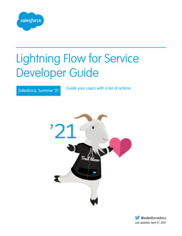
www.PDHcenter.comPDH Course E367www.PDHonline.orgshown below. The wide plate supporting the terminal provided the enclosure bonding.The location of the air terminals on the building ridge are at the discretion of the designer, so long asthey are not closer than 2-ft to the end of the ridge and are spaced no more than 20-ft apart. Note thatthis is a LOT of terminals. That is what the Standard requires. Main cable and downcomer supportsmust be at 3-ft intervals or less.The ground rod was mentioned previously. First choice is a 10-ft copper-clad steel rod with at least 8-ftin contact with earth, located at least 2-ft from the foundation, but not much farther. If there is a hazardof damage to the downcomer, it must be protected by conduit a minimum of 8-ft above finished grade.It is very, very common to find the section of the downcomer between the wall and the rod missing.Best installation is to place the short horizontal section below grade.There are parts of the country where topsoil, or overburden, as it is called in the Standard, is veryshallow. It is permitted to drive the ground rod diagonally or even lay it in a trench, horizontally. Inthe extreme, the rod can be attached by anchors or epoxy to bed rock. It is pointed out that these arenot good grounds. If you want a good ground under these conditions, you must lay a ground loop ofmain-size cable around the perimeter of the building. We will see ground loops again as the preferredgrounding for tall buildings.What about the missing piece of downcomer ? Why all the fuss about a good ground ?The underlying question is, “Why are we putting in a lightning protection system?”In Tampa, there will be hundreds of nearby lightning strikes each year. In Florida, all schools and Statebuildings must have lightning protection systems. In the rest of the country, not so much. SeeIsokeraunic Map, below: Thomas MasonPage 6 of 18
www.PDHcenter.comPDH Course E367www.PDHonline.orgNumber of Days with Thunderstorms, http://ecmweb.com/mag/electric lightning strikes/Beyond Florida, I am aware of no requirement for lightning protection. Real-world application isspotty. It is common for public utilities to have two substations, side-by-side. One with lightningprotection towers and catenaries and the other withoutI often suspect that requests for lightning protection systems immediately follow a perceivedcatastrophic loss.My favorite example is a meter shed adjacent to a 500-ft incinerator stack. The stack had an excellentlightning protection system. The 6-ft x 6-ft shed had two terminals and two ground rods. In theterminology of NFPA-780, the shed was within the zone of protection of the stack. None of the otherbuildings at the plant had lightning protection.We design lightning protection systems to NFPA-780 when a Client asks for lightning protection. Wedo not guarantee effectiveness, only that it complies with the Standard and we require a Master SystemLabel from the installer.Returning to the Corner Downcomer illustration, utility grounding is required by the NationalElectrical Code (NEC). The requirements have evolved to presently requiring an intersystem groundterminal. It is not required retroactively, but is requir
Designing to Lightning Standard, NFPA 780-2011 . Thomas Mason, PE . The goal of this course is to learn how to design lightning protection systems. Fortunately, it is very easy. Please consider the following four examples: This illustration is for orientation. This illustration identifies the components and introduces the basic rules for an NFPA 780-2011 lightning protection system. To the .File Size: 1MBPage Count: 18