Transcription
PORSCHE 911 GT3 RUSER MANUAL1
Table of ContentsCLICK TO VIEW A SECTIONGENERAL INFORMATIONA Message From iRacing » 3Tech Specs » 4Introduction » 5Getting Started » 5Loading An iRacing Setup » 6Dash Pages » 7Race 1 » 7Race 2» 9Quali » 11Lockup Light Clusters » 12Traction Control Activation » 12Pit Limiter & Shift Lights » 13ADVANCED SETUP OPTIONSTires & Aero » 14Tire Settings » 14Aerodynamics » 15Chassis » 17Front End » 17In-Car Dials » 19Front Corners » 20Rear Corners » 22Rear End » 24P ORS CHE 911 G T3 R USER M ANUAL2
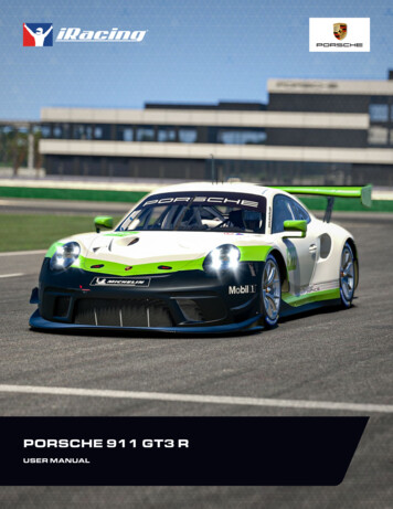
DE AR iR ACING USER,Congratulations on your purchase of the Porsche 911 GT3 R! From all of us at iRacing, we appreciate yoursupport and your commitment to our product. We aim to deliver the ultimate sim racing experience, and wehope that you’ll find plenty of excitement with us behind the wheel of your new car!GT3s have proven to be some of the most popular road racing cars in the world in recent years, andfew brands have quite the road racing pedigree of Porsche. It should stand as no surprise, then, that thePorsche 911 GT3 R is both a beloved and successful piece of kit. Immediately successful out of the gatethanks to a win in its first attempt at the Bathurst 12 Hour, you can find the 911 GT3 R running at the frontof the field everywhere from the IMSA WeatherTech SportsCar Championship to the Intercontinental GTChallenge. The 4.0-liter flat-six boxer engine produces a whopping 543 horsepower, more than enough topropel you to the front of the pack!The following guide explains how to get the most out of your new car, from how to adjust its settings off ofthe track to what you’ll see inside of the cockpit while driving. We hope that you’ll find it useful in getting upto speed.Thanks again for your purchase, and we’ll see you on the track!3
PORSCHE 911 GT3 R TECH SPECSCHASSISDOUBLE W ISHBONE FRON T SUSPENSION,MULT I-LINK RE AR LBASEDRY WEIGHTWET WEIGHTWITH NITWATER-COOLED REARMOUNTED FLAT-6 BOXERDISPLACEMENT4.0 Liters244.14CIDP ORS CHE 911 G T3 R RPM LIMIT9450RPMUSER M ANUALTORQUE280lb-ft380NmPOWER500bhp374kW4
PORSCHE 911 GT3 R INTRODUCTIONIntroductionThe information found in this guide is intended to provide a deeper understanding of thechassis setup adjustments available in the garage, so that you may use the garage to tunethe chassis setup to your preference.Before diving into chassis adjustments, though, it is best to become familiar with the carand track. To that end, we have provided baseline setups for each track commonly racedby these cars. To access the baseline setups, simply open the Garage, click iRacing Setups,and select the appropriate setup for your track of choice. If you are driving a track for whicha dedicated baseline setup is not included, you may select a setup for a similar track to useas your baseline. After you have selected an appropriate setup, get on track and focus onmaking smooth and consistent laps, identifying the proper racing line and experiencing tirewear and handling trends over a number of laps.Once you are confident that you are nearing your driving potential with the included baselinesetups, read on to begin tuning the car to your handling preferences.GETTING STARTEDBefore starting the car, it is recommended to map controls for Brake Bias, Traction Control and ABS adjustments. While this isnot mandatory to drive the car, this will allow you to make quick changes to the driver aid systems to suit your driving style whileout on the track.Once you load into the car, getting started is as easy as selecting the “upshift” button to put it into gear, and hitting theaccelerator pedal. This car uses a sequential transmission and does not require a clutch input to shift in either direction. However,the car’s downshift protection will not allow you to downshift if you are traveling too fast for the gear selected and would incurengine damage. If that is the case, the gear change command will simply be ignored.Upshifting is recommended at the illumination of the last two yellow shift lights on the dashboard. This is at approximately 9000rpm.P ORS CHE 911 G T3 R USER M ANUAL5
PORSCHE 911 GT3 R INTRODUCTIONLOADING AN iRACING SETUPWhen you first load into a session, the iRacing Baseline setup will be automatically loaded onto the car. If you would like to try anyof the other iRacing pre-built options, you may select it by going to Garage iRacing Setups and then selecting another optionthat fits your needs. Because this car uses slightly different chassis and body configurations on different types of tracks, it willbe necessary to load a setup from the same track type to pass tech inspection. For example, a setup for Talladega will pass atDaytona, but likely will not pass at Bristol.If you would like to customize the setup, simply make the changes in the garage that you would like to update and click apply. Ifyou would like to save your setup for future use click “Save As” on the right to name and save the changes. To access all of yourpersonally saved setups, click “My Setups” on the right side of the garage. If you would like to share a setup with another driver oreveryone in a session, you can select “Share” on the right side of the garage to do so. If a driver is trying to share a setup with you,you will find it under “Shared Setups” on the right side of the garage as well.P ORS CHE 911 G T3 R USER M ANUAL6
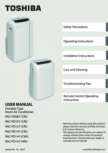
PORSCHE 911 GT3 R DASH PAGESDash PagesThe digital dash display in this car features three selectable pages (Race 1, Race 2 andQual) as well as numerous light clusters to convey critical information to the driver. Race 1and Race 2 are largely identical aside from the upper left cluster; Race 1 uses this clusterto display critical engine parameters (oil temperature, oil pressure, water temperature andwater pressure) while Race 2 uses this space to display relevant fuel calculations (fuel usedthis stint, fuel consumption per lap, fuel pressure and current fuel level). ‘Qual’ forgoes mostof these detailed parameters and instead displays only lap time, predicted lap time and totalfuel remaining.RACE 1ROW 1 LEF TRACE 1 Currently selected dash pageDRY Currently fitted tireHEADLIGHT ICONCurrent headlight setting (non-adjustable)ROW 1 CEN T ERNUMBER Currently vehicle speed (km/h or mph)ROW 1 RIGH TLAP Current session lapAC-0 Currently selected A/C map (non-adjustable)ROW 2 LEF TOIL TEMPEngine oil temperature ( C or F)OIL PRESSEngine oil pressure (bar or psi)WATER TEMPEngine water temperature ( C or F)WATER PRESSEngine water pressure (bar or psi)P ORS CHE 911 G T3 R USER M ANUAL7
PORSCHE 911 GT3 R DASH PAGESROW 2 CEN T ERLARGE NUMBERCurrently selected gearROW 2 RIGH TLAP TIMELast lap timeTIME DIFFDifference to last lapPRED LAPPredicted current lap timeROW 3 LEF TMAP-# Currently selected engine mapTH-S # Currently selected throttle mapS12-3 ensor backup function position (non-adjustable)G12-6 Gearbox backup function position (non-adjustable)ROW 3 CEN T ERTYRE PRESSTire Pressures (left front, right front, left rear, right rear)ROW 4MIL Malfunction indicatorABS-# Currently selected ABS mapTC-C # Currently selected TCC mapTC-R # Currently selected TCR mapP ORS CHE 911 G T3 R USER M ANUAL8
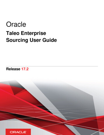
PORSCHE 911 GT3 R DASH PAGESRACE 2ROW 1 LEF TRACE 2 Currently selected dash pageDRY Currently fitted tireHEADLIGHT ICONCurrent headlight setting (non-adjustable)ROW 1 CEN T ERNUMBER Currently vehicle speed (km/h or mph)ROW 1 RIGH TLAP Current session lapAC-0 Currently selected A/C map (non-adjustable)ROW 2 LEF TFUEL USEDFuel used (Litres or US gallons)FUEL PER LAPFuel used per lap (Litres or US gallons)FUEL PRESSFuel pressure (Bar or psi)FUEL LEVELFuel remaining in the tank (Litres or US gallons)ROW 2 CEN T ERLARGE NUMBERCurrently selected gearROW 2 RIGH TLAP TIMELast lap timeTIME DIFFDifference to last lapPRED LAPPredicted current lap timeP ORS CHE 911 G T3 R USER M ANUAL9
PORSCHE 911 GT3 R DASH PAGESROW 3 LEF TMAP-# Currently selected engine mapTH-S # Currently selected throttle mapS12-3 ensor backup function position (non-adjustable)G12-6 Gearbox backup function position (non-adjustable)ROW 3 CEN T ERTYRE PRESSTire Pressures (left front, right front, left rear, right rear)ROW 4MIL Malfunction indicatorABS-# Currently selected ABS mapTC-C # Currently selected TCC mapTC-R # Currently selected TCR mapP ORS CHE 911 G T3 R USER M ANUAL10
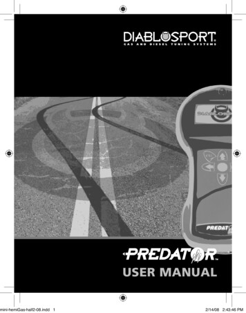
PORSCHE 911 GT3 R DASH PAGESQUALIROW 1 LEF TQUALI Currently selected dash pageDRY Currently fitted tireHEADLIGHT ICONCurrent headlight setting (non-adjustable)ROW 1 CEN T ERNUMBER Currently vehicle speed (km/h or mph)ROW 1 RIGH TLAP Current session lapAC-0 Currently selected A/C map (non-adjustable)ROW 2 LEF TLAP TIMECurrent session lapFUEL LEVELFuel remaining in the tank (Litres or US gallons)ROW 2 CEN T ERLARGE NUMBERCurrently selected gearROW 2 RIGH TPREDICTED LAP TIMEPredicted current lap timeROW 3 LEF TMAP-# Currently selected engine mapTH-S # Currently selected throttle mapS12-3 ensor backup function position (non-adjustable)G12-6 Gearbox backup function position (non-adjustable)P ORS CHE 911 G T3 R USER M ANUAL11
PORSCHE 911 GT3 R DASH PAGESROW 3 CEN T ERTYRE PRESSTire Pressures (left front, right front, left rear, right rear)ROW 4MIL Malfunction indicatorABS-# Currently selected ABS mapTC-C # Currently selected TCC mapTC-R # Currently selected TCR mapLOCKUP LIGHT CLUSTERSWhen the front wheels lock, purple LED’s illuminate on two pods located on the instrument binnacle corresponding to the roadwheel that’s locking (e.g. left side lights in purple indicate a front left lockup). The number of lights indicates the severity of thelockup, with one light being a minor lockup and four being severe. This light illumination behaviour is identical for the rear wheelswith the exception that these are indicated by yellow LED illumination instead of purple.TRACTION CONTROL ACTIVATIONWhen traction control is active all lights in the lockup light clusters illuminate in blue along with four lights on the digital displayilluminating in purple.P ORS CHE 911 G T3 R USER M ANUAL12
PORSCHE 911 GT3 R DASH PAGESPIT LIMITERWhen the pit limiter is active (and you are under the pit speed limit) a large green box that includes the current road speed willdisplay across the top of the dashboard while the left and right lockup light clusters will also illuminate completely in green. Shouldyou be above the pit speed limit the green box will switch to orange.SHIFT LIGHTS2 GREEN8400 rpm4 GREEN8600 rpm2 YELLOW8800 rpm4 YELLOW9000 rpm2 RED9200 rpmP ORS CHE 911 G T3 R USER M ANUAL13
PORSCHE 911 GT3 R ADVANCED SETUP OPTIONS TIRES & AEROADVANCED SETUP OPTIONSThis section is aimed toward more advanced users who want to dive deeper into the different aspectsof the vehicle’s setup. Making adjustments to the following parameters is not required and can lead tosignificant changes in the way a vehicle handles. It is recommended that any adjustments are made inan incremental fashion and only singular variables are adjusted before testing changes.Tires & AeroTIRE SETTINGS (ALL FOUR TIRES)C OLD AIR PRES SUREAir pressure in the tire when the car is loaded into the world. Higher pressures will reduce rolling drag and heat buildup, but willdecrease grip. Lower pressures will increase rolling drag and heat buildup, but will increase grip. Higher speeds and loads requirehigher pressures, while lower speeds and loads will see better performance from lower pressures. Cold pressures should be setto track characteristics for optimum performance. Generally speaking, it is advisable to start at lower pressures and work yourway upwards as required.P ORS CHE 911 G T3 R USER M ANUAL14
PORSCHE 911 GT3 R ADVANCED SETUP OPTIONS TIRES & AEROHO T AIR PRES SUREAir pressure in the tire after the car has returned to the pits. The difference between cold and hot pressures can be used toidentify how the car is progressing through a run in terms of balance, with heavier-loaded tires seeing a larger difference betweencold and hot pressures. Ideally, tires that are worked in a similar way should build pressure at the same rate to prevent a changein handling balance over the life of the tire, so cold pressures should be adjusted to ensure that similar tires are at similarpressures once up to operating temperature. Hot pressures should be analysed once the tires have stabilised after a period oflaps. As the number of laps per run will vary depending upon track length a good starting point is approximately 50% of a full fuelrun.T IRE T EMPER AT URESTire carcass temperatures, measured via Pyrometer, once the car has returned to the pits. Wheel Loads and the amount of worka tire is doing on-track are reflected in the tire’s temperature, and these values can be used to analyze the car’s handling balance.Center temperatures are useful for directly comparing the work done by each tire, while the Inner and Outer temperatures areuseful for analyzing the wheel alignment (predominantly camber) while on track. These values are measured in three zones acrossthe tread of the tire. Inside, Middle and Outer.T RE AD REM AININGThe amount of tread remaining on the tire once the car has returned to the pits. Tire wear is very helpful in identifying any possibleissues with alignment, such as one side of the tire wearing excessively, and can be used in conjunction with tire temperatures toanalyze the car’s handling balance. These values are measured in the same zones as those of temperature.AERO CALCULATORThe Aero Calculator is a tool provided to aid in understanding the shift in aerodynamicbalance associated with adjustment of the rear wing setting and front and rear rideheights. It is important to note that the values for front and rear ride height displayed hereDO NOT result in any mechanical changes to the car itself, however, changes to the rearwing angle here WILL be applied to the car. This calculator is a reference tool ONLY.FRON T RH AT SPEEDThe Ride Height (RH) at Speed is used to give the Aero Calculator heights to reference for aerodynamic calculations. When usingthe aero calculator, determine the car’s Front Ride height via telemetry at any point on track and input that value into the “FrontRH at Speed” setting. It is advisable to use an average value of the LF and RF ride heights as this will provide a more accuraterepresentation of the current aero platform rather than using a single corner height.P ORS CHE 911 G T3 R USER M ANUAL15
PORSCHE 911 GT3 R ADVANCED SETUP OPTIONS TIRES & AERORE AR RH AT SPEEDThe Ride Height (RH) at Speed is used to give the Aero Calculator heights to reference for aerodynamic calculations. When usingthe aero calculator, determine the car’s Rear Ride height via telemetry at any point on track and input that value into the “FrontRH at Speed” setting. It is advisable to use an average value of the LR and RR ride heights as this will provide a more accuraterepresentation of the current aero platform rather than using a single corner height.W ING SE T T INGThe wing setting refers to the relative angle of attack of the rear wing, this is a powerful aerodynamic device which has asignificant impact upon the total downforce (and drag!) produced by the car as well as shifting the aerodynamic balance of the carrearwards with increasing angle. Increasing the rear wing angle results in more total cornering grip capability in medium to highspeed corners but will also result in a reduction of straight line speed. Rear wing angle should be adjusted in conjunction with frontand rear ride heights, specifically the difference between front and rear ride heights known as ‘rake’. To retain the same overallaerodynamic balance it is necessary to increase the rake of the car when increasing the rear wing angle.FRON T DOW NFORCEThis value displays the proportion of downforce acting at the front axle for the given wing and ride height combination set withinthe calculator parameters. This value is an instantaneous representation of your aero balance at this exact set of parameters andit can be helpful to pick multiple points around a corner or section of track to understand how the aerodynamic balance is movingin differing situations such as braking, steady state cornering and accelerating at corner exit. A higher forwards percentage willresult in more oversteer in mid to high speed corners.P ORS CHE 911 G T3 R USER M ANUAL16
PORSCHE 911 GT3 R ADVANCED SETUP OPTIONS CHASSISChassisFRONTARB BL ADESThe configuration of the Anti-Roll Bar arms, or “blades”, can be changed to alter the overall stiffness of the ARB assembly. Highervalues transfer more force through the arms to the ARB itself, increasing roll stiffness in the front suspension and producingthe same effects, albeit on a smaller scale, as increasing the diameter of the sway bar. Conversely, lower values reduce theroll stiffness of the front suspension and produce the same effects as decreasing the diameter of the sway bar. These bladeadjustments can be thought of as fine-tuning adjustments between sway bar diameter settings. 3 ARB blade options are availableranging from soft to hard.ARB OU T ER DI AME T ERThe ARB (Anti-Roll Bar) size influences the stiffness of the front suspension in roll, such as when navigating a corner. Increasing theARB size will increase the roll stiffness of the front suspension, resulting in less body roll but increasing mechanical understeer.This can also, in some cases, lead to a more responsive steering feel from the driver. Conversely, reducing the ARB size will softenthe suspension in roll, increasing body roll but decreasing mechanical understeer. This can result in a less-responsive feel fromthe steering, but grip across the front axle will increase. Along with this, the effects of softening or stiffening the ARB in relation toaerodynamics should also be considered, smaller and hence softer ARB’s will result in more body roll which will decrease controlof the aero platform in high speed corners and potentially lead to a loss in aero efficiency. 2 configurations of ARB diameter areavailable; 35 mm (softest) and 45 mm (stiffest).P ORS CHE 911 G T3 R USER M ANUAL17
PORSCHE 911 GT3 R ADVANCED SETUP OPTIONS CHASSIST OE -INToe is the angle of the wheel, when viewed from above, relative to the centerline of the chassis. Toe-in is when the front of thewheel is closer to the centerline than the rear of the wheel, and Toe-out is the opposite. On the front end, adding toe-out willincrease slip in the inside tire while adding toe-in will reduce the slip. This can be used to increase straight-line stability and turn-inresponsiveness with toe-out. Toe-in at the front will reduce turn-in responsiveness but will reduce temperature buildup in the fronttires.FRON T M AS T ER CYLINDERThe Front Brake Master Cylinder size can be changed to alter the line pressure to the front brake calipers. A larger mastercylinder will reduce the line pressure to the front brakes, this will shift the brake bias rearwards and increase the pedal effortrequired to lock the front wheels. A smaller master cylinder will do the opposite and increase brake line pressure to the frontbrakes, shifting brake bias forward and reducing required pedal effort. 7 Different master cylinder options are available rangingfrom 15.9 mm / 0.626” (highest line pressure) to 23.8 mm / 0.937” (lowest line pressure).RE AR M AS T ER CYLINDERThe Rear Brake Master Cylinder size can be changed to alter the line pressure to the rear brake calipers. A larger master cylinderwill reduce the line pressure to the rear brakes, this will shift the brake bias forwards and increase the pedal effort required tolock the rear wheels. A smaller master cylinder will do the opposite and increase brake line pressure to the rear brakes, shiftingbrake bias rearward and reducing required pedal effort. 7 Different master cylinder options are available ranging from 15.9 mm /0.626” (highest line pressure) to 23.8 mm / 0.937” (lowest line pressure).BR AK E PADSThe vehicle’s braking performance can be altered via the Brake Pad Compound. The “Low” setting provides the least friction,reducing the effectiveness of the brakes, while “Medium” and “High” provide more friction and increase the effectiveness of thebrakes while increasing the risk of a brake lockup.FUEL LE V ELThe amount of fuel in the fuel tank. Tank capacity is 120 L (31.7 g). Adjustable in 1 L (0.26 g) increments.CROS S W EIGH TThe percentage of total vehicle weight in the garage acting across the right front and left rear corners. 50.0% is generally optimalfor non-oval tracks as this will produce symmetrical handling in both left and right hand corners providing all other chassis settingsare symmetrical. Higher than 50% cross weight will result in more understeer in left hand corners and increased oversteer inright hand corners, cross weight can be adjusted by making changes to the spring perch offsets at each corner of the car.P ORS CHE 911 G T3 R USER M ANUAL18
PORSCHE 911 GT3 R ADVANCED SETUP OPTIONS CHASSISIN-CAR DIALSDISPL AY PAGEChanges the currently selected digital dash page. 3 options are available, Race 1, Race 2 and Qual as previously described in thedash configuration section of this manual.BR AK E PRES SURE BI ASBrake Bias is the percentage of braking force that is being sent to the front brakes. Values above 50% result in greater pressurein the front brake line relative to the rear brake line which will shift the brake balance forwards increasing the tendency to lockup the front tyres but potentially increasing overall stability in braking zones. This should be tuned for both driver preference andtrack conditions to get the optimum braking performance for a given situation. It is important to note that differing combinationsof master cylinder size will necessitate differing brake pressure bias values, this is because increasing or reducing the split inmaster cylinder size difference between front and rear axles will produce an inherent forward or rearward bias in brake linepressure.T R AC T ION C ON T ROL SE T T ING ( T C C)The position of this traction control switch determines how aggressively the ecu cuts engine torque in reaction to rear wheel spin.12 positions are available. Settings 1-11 range from least intervention/sensitivity (position 1) through to highest intervention/sensitivity (position 11). Position 0 disables the traction control completely. Position 5 is the recommended baseline setting.More intervention will result in less wheelspin and less rear tire wear but can reduce overall performance if the traction control iscutting engine torque too aggressively and stunting corner exit acceleration.T R AC T ION C ON T ROL SE T T ING ( T CR )The position of this traction control switch determines the slip sensitivity of the traction control (how much slip is allowable beforetorque cut is implemented) rather than the overall intervention strength. Settings 0-11 range from least slip sensitivity (position0) to most slip sensitivity (position 11). Position 0 does NOT disable the traction control as it does with the TCC setting. Position 5is the recommended baseline setting.T HRO T T LE M AP SE T T INGThrottle map setting refers to how changes in the drivers pedal position result in changes in provided engine torque. 5 positionsexist, position 4 results in a linear torque map relative to throttle position (e.g. 10% throttle position results in 10% engine torque,50% throttle position results in 50% engine torque and so on.). Position 0 emulates a non-linear S-shaped map similar to a cablethrottle which results in reduced fidelity in the middle portion of the throttle range. Positions 1-3 are hybrids of the position 0 and4 throttle mapping styles.P ORS CHE 911 G T3 R USER M ANUAL19
PORSCHE 911 GT3 R ADVANCED SETUP OPTIONS CHASSISA B S SE T T INGThe current ABS map the car is running. 12 positions are available but only 10 maps exist. Position 1 has the least intervention/support while position 10 has the most support. Position 10 is the same as position 11 and position 0 disables the ABScompletely. Position 4 is the recommended baseline setting. More intervention reduces the possibility of and the duration oflockups during braking but can result in longer braking distances if the system is set overly aggressive for the amount of availablegrip.ENGINE M AP SE T T INGThe fuel map on which the car is currently running. Position 4 is the base map and produces maximum power but the most fuelusage. Positions 3 through 2 are for fuel saving under green flag conditions and will reduce engine power output correspondingly.The lower the number the better the fuel economy but the lower the power output. Positions 1 and 0 are for saving fuel undersafety car conditions and are not recommended for normal usage.FRONT CORNERSC ORNER W EIGH TThe weight underneath each tire under static conditions in the garage. Correct weight arrangement around the car is crucial foroptimizing a car for a given track and conditions. Individual wheel weight adjustments and crossweight adjustments are made viathe spring perch offset adjustments at each corner.FRON T RIDE HEIGH TDistance from ground to a reference point on the chassis. Since these values are measured to a specific reference point on thecar, these values may not necessarily reflect the vehicle’s ground clearance, but instead provide a reliable value for the height ofthe car off of the race track at static values. Adjusting Ride Heights is key for optimum performance, as they can directly influencethe vehicle’s aerodynamic performance as well as mechanical grip. Increasing front ride height will decrease front downforceas well as decrease overall downforce, but will allow for more weight transfer across the front axle when cornering. Conversely,reducing ride height will increase front and overall downforce, but reduce the weight transfer across the front axle. Minimum legalfront ride height is 50.0 mm.SPRING PERCH OFF SE TUsed to adjust the ride height at this corner of the car by changing the installed position of the spring. Increasing the spring perchoffset will result in lowering this corner of the car while reducing the spring perch offset will raise this corner of the car. Thesechanges should be kept symmetrical across the axle (left to right) to ensure the same corner ride heights and no change in crossweight. The spring perch offsets can also be used in diagonal pairs (LF to RR and RF to LR) to change the static cross weight inthe car.P ORS CHE 911 G T3 R USER M ANUAL20
PORSCHE 911 GT3 R ADVANCED SETUP OPTIONS CHASSISSPRING SELEC T ED/SPRING R AT EThis setting determines the installed corner spring stiffness. Stiffer springs will result in a smaller variance in ride height betweenhigh and low load cases and will produce superior aerodynamic performance through improved platform control; however, theywill also result in increased tire load variation which will manifest as a loss in mechanical grip. Typically the drawbacks of stiffersprings will become more pronounced on rougher tracks and softer springs in these situations will result in increased overallperformance. Corner spring changes will influence both roll and pitch control of the platform and ARB changes should beconsidered when altering corner spring stiffnesses in order to retain the same front to rear roll stiffness and overall balance.When reducing corner spring stiffness the ARB stiffness (either via blade or diameter depending on the size of the corner springchange) should be increased to retain the same roll stiffness as previously. 11 options for spring rate are available ranging from200 N/mm (1371 lbs/in) to 400 N/mm (2286 lbs/in) in 20 N/mm (114 lbs/in) steps. Spring perch offsets must be adjustedto return the car to the prior static ride heights after any spring rate change.L S C OMP DAMPINGLow speed compression affects how resistant the shock is to compresion (reduction in length) when the shock is moving atrelatively low speeds, usually in chassis movements as a result of driver input (steering, braking, & throttle) and corneringforces. In this case -24 is minimum damping (least resistance to compression) while 0 is maximum damping (most resistance tocompression). Increasing the low speed compression damping will result in a faster transfer of weight to this corner of the carduring transient movements such as braking and direction change with increased damping usually providing an increase in turn-inresponse but a reduction in overall grip in the context of front dampers.HS C OMP DAMPINGHigh speed compression affects the shock’s behavior in high speed travel, usually attributed to curb strikes and bumps in thetrack’s surface. Higher compression values will cause the suspension to be stiffer in these situations, while lower values will allowthe suspension to absorb these bumps better but may hurt the aerodynamic platform around the track. At smoother tracks morehigh speed compression damping will typically increase performance while at rougher tracks or ones with aggressive kerbs lesshigh speed compression damping can result in an increase in mechanical grip at the expense of platform control. 0 is maximumdamping while -24 is minimum damping.L S RBD DAMPINGLow speed rebound damping controls the stiffness of the shock while extending at lower speeds, typically during body movementas a result of driver inputs. Higher rebound values will resist expansion of the shock, lower values will allow the shock to extendfaster. Higher rebound values can better control aerodynamic attitude but can result in the wheel being unloaded when thesuspension can’t expand enough to maintain proper contact with the track. When tuning for handling, higher front lo
PORSCHE 911 GT3 R USER MANUAL 2 Introduction » 5 Tech Specs » 4 A Message From iRacing » 3 Getting Started » 5 Race 2» 9 Dash Pages » 7 Loading An iRacing Setup » 6 Quali » 11 Race 1 » 7 Lockup Light Clusters » 12 Tire Settings » 14 Pit Limiter & Shift Lights » 13 Chassis » 17 Traction Control Activation » 12 Ae