Transcription
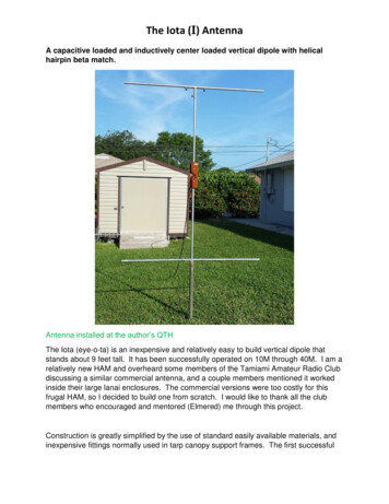
Design GuideDynaform FiberglassStructuralShapesCorrosion ResistantFire RetardantLow MaintenanceLight WeightLong Service LifeQHigh Performance Composite SolutionsUALITYISO9001-2000CERTIFIED
Table of ContentsPultrusion Process . . . . . . . . . . . . . . . . . . . . . . . . . . . . . . . . . . . . . . . . . . 3Resin Systems for Structural Shapes. . . . . . . . . . . . . . . . . . . . . . . . . . . . 4Elevated Temperature Effects. . . . . . . . . . . . . . . . . . . . . . . . . . . . . . . . . . 4Chemical Resistance Guide. . . . . . . . . . . . . . . . . . . . . . . . . . . . . . . . . . . 5Structural Shapes. . . . . . . . . . . . . . . . . . . . . . . . . . . . . . . . . . . . . . . 5Vinyl Ester Threaded Rod . . . . . . . . . . . . . . . . . . . . . . . . . . . . . . . . 7Coupon Properties . . . . . . . . . . . . . . . . . . . . . . . . . . . . . . . . . . . . . . . . . . 8Structural Shapes. . . . . . . . . . . . . . . . . . . . . . . . . . . . . . . . . . . . . . . 8Pultruded Flat Sheet . . . . . . . . . . . . . . . . . . . . . . . . . . . . . . . . . . . . . 9Vinyl Ester Threaded Rods and Nuts . . . . . . . . . . . . . . . . . . . . . . . 10Cross Sectional Tolerances. . . . . . . . . . . . . . . . . . . . . . . . . . . . . . . . . . . 11Section Properties. . . . . . . . . . . . . . . . . . . . . . . . . . . . . . . . . . . . . . . . . . 15Beams - Allowable Uniform Load Tables . . . . . . . . . . . . . . . . . . . . . . . 24Wide Flange Beams. . . . . . . . . . . . . . . . . . . . . . . . . . . . . . . . . . . . . 26I Beams. . . . . . . . . . . . . . . . . . . . . . . . . . . . . . . . . . . . . . . . . . . . . . 33Channels . . . . . . . . . . . . . . . . . . . . . . . . . . . . . . . . . . . . . . . . . . . . . 42Square Tubes . . . . . . . . . . . . . . . . . . . . . . . . . . . . . . . . . . . . . . . . . 51Rectangular Tubes . . . . . . . . . . . . . . . . . . . . . . . . . . . . . . . . . . . . . 53Structural Connections . . . . . . . . . . . . . . . . . . . . . . . . . . . . . . . . . . . . . . 55Stringer Design Tables . . . . . . . . . . . . . . . . . . . . . . . . . . . . . . . . . . . . . . 56OSHA . . . . . . . . . . . . . . . . . . . . . . . . . . . . . . . . . . . . . . . . . . . . . . . 56UBC. . . . . . . . . . . . . . . . . . . . . . . . . . . . . . . . . . . . . . . . . . . . . . . . . 57Columns - Allowable Axial Load Tables. . . . . . . . . . . . . . . . . . . . . . . . . 58Angles . . . . . . . . . . . . . . . . . . . . . . . . . . . . . . . . . . . . . . . . . . . . . . 60I Shapes . . . . . . . . . . . . . . . . . . . . . . . . . . . . . . . . . . . . . . . . . . . . . 69Wide Flange Shapes . . . . . . . . . . . . . . . . . . . . . . . . . . . . . . . . . . . . 78Square Tubes . . . . . . . . . . . . . . . . . . . . . . . . . . . . . . . . . . . . . . . . . 87Rectangular Tube. . . . . . . . . . . . . . . . . . . . . . . . . . . . . . . . . . . . . . 93Round Tube . . . . . . . . . . . . . . . . . . . . . . . . . . . . . . . . . . . . . . . . . . 94
Pultrusion ProcessPultrusion is a continuous process of raw materials, typically resin and reinforcing materials,forming profiles of constant cross section in continuous length.Pultrusion gets its name from the method by which the profiles are made. Raw materialsare literally pulled by what we call "the puller." "The puller" is the machine made up of pullingpads, which grip the product, and a drive system which keeps the product moving. "The puller"is located just before the final cut-off saw.The process starts with the reinforcements. Typically, unidirectional glass roving is thefiber that runs along the length of the profile. Second, the fiberglass mat is added in, which ismultidirectional reinforcement. Third is the resin, typically polyester or vinylester. The glass is"wet-out" with the liquid resin and pulled into a heated die. Just before all the material enters thedie, surface veil may be added which enhances the final product's surface.Now that all the reinforcements have been "wet-out" and pulled into a heated die, the curingtakes place. All the resins used in the pultrusion process have a catalyst or hardener addedwhen the resin is mixed. This catalyst activated at about 200 F. Consequently, as the "wet-out"reinforcement pass through the heated die, the product changes from liquid to a solid profilewith all the reinforcement laminated within.The product exiting the die is pulled by "the puller", which upon exiting can be cut to thedesired length.
Standard Resin Systems for Structural ShapesSTANDARD POLYESTER (ISO or PN) RESIN SYSTEMThe STANDARD POLYESTER RESIN SYSTEM refers to a NON FLAME RETARDANTisophthalic polyester resin system. This resin system is manufactured in olive green andincorporates ultraviolet inhibitors. Polyester resins exhibit good corrosion resistance, goodelectrical properties, low thermal conductivity and excellent mechanical properties.FLAME RETARDANT POLYESTER (ISOFR or PF) RESIN SYSTEMThis resin system exhibits the same characteristics as the Standard Polyester resin system PLUSa flame spread rating of 25 or less when tested in accordance with ASTM E-84. The FLAMERETARDANT resin system is manufactured in gray and yellow.FLAME RETARDANT VINYL ESTER (VEFR or VF) RESIN SYSTEMThis resin system is manufactured from vinyl ester resin which exhibits higher strength,improved strength and stiffness retention at elevated temperatures, and improved corrosionresistance. This system also meets a maximum flame spread rating of 25 and is produced inbeige and yellow.ELEVATED TEMPERATURE EFFECTSThe approximate retention of mechanical properties at elevated temperatures are:Ultimate StressModulus of ElasticityTEMPERATURE100 F125 F150 F175 F200 FISO(PN)/ISOFR(PF)85%70%50%Not RecommendedNot RecommendedVEFR(VF)90%80%80%75%50%100 F125 F150 F175 F200 F100%90%85%Not RecommendedNot Recommended100%95%90%88%85%
Chemical Resistance Guide - Structural ShapesThe data in this chemical resistance guide is based on field service performance, laboratory testing and extrapolated valuesfrom our resin manufacturers' recommendation. Data shown is intended as a guide only. It is recommended that for a specificapplication, testing be done in the actual chemical environment.The following conditions will effect the suitability of a specific resin laminate: Periodic changes in temperature Exposure to frequent splashes and spills Temperature spikes Exposure to intermittent splashes and spills Changes in chemical concentrations Frequency of maintenance wash down Combinations of chemicals Load bearing or non-load bearing requirements Exposure to vapors mperatures, FVEFRISO/ISOFRAcetic Acid, to 10%17080180NRAcetic Acid, to 50%Acetic Acid, GlacialNRNRAcetoneNRNRAluminum Chloride170120Aluminum Hydroxide140120Aluminum Nitrate140120Aluminum Sulfate170120Ammonium Chloride170120NRAmmonium Hydroxide, 5%140170120Ammonium Nitrate, to 50%Ammonium Nitrate, Saturated170NR90Ammonium Persulfate, to 25% 140Ammonium Phosphate170120Ammonium Sulfate170120Amyl Alcohol80NRBarium Carbonate170120Barium Chloride170120Barium Sulfate170120BenzeneNRNR110NRBenzene Sulfonic Acid 50%Benzoic Acid170120Benzyl AlcoholNRNRBorax170120Brine (Sodium Chloride Sol.)170120Bromine, Liquid or VaporNRNREthyl AlcoholNRNREthylene Glycol170120Fatty Acids17080Ferric Chloride170100Ferric Sulfate170110Formaldehyde110NRFuel Oil14080Gasoline, Aviation and Ethyl14080 ChemicalEnvironmentButyl AcetateButyl AlcoholCalcium CarbonateCalcium HydroxideCalcium HypochloriteCalcium NitrateCalcium SulfateCarbon DisulfideCarbon Monoxide GasCarbon Dioxide GasCarbon TetrachlorideLiquid or VaporChlorine, Dry GasChlorine, Wet GasChlorine WaterChloroformChromic Acid, to 5%Chromous SulfateCitric AcidCopper ChlorideCopper CyanideCopper NitrateCrude Oil, SourCyclohexane, Liquid and VaporDiesel FuelEthyl AcetatePhosphoric Acid, VaporPotassium Aluminum SulfatePotassium BicarbonatePotassium Carbonate, to 10%Potassium ChloridePotassium HydroxidePotassium NitratePotassium SulfateMaximumRecommendedServiceTemperatures, FVEFR 170170170NR90NR120120100NR120NR120120
Chemical Resistance Guide - Structural Temperatures, FVEFR draulic Fluid (Glycol Based)140NRHydraulic Fluid Skydraul140NRHydrobromic Acid110NRHydrochloric Acid, up to 15%14080Hydrochloric Acid, Concentrated 110NRHydrogen Bromide, Dry Gas14080Hydrogen Bromine, Wet Gas140NRHydrogen Chloride, Dry Gas17080Hydrogen Chloride, Wet Gas17080Hydrogen Flouride, Sol or Vapor 140NRHydrogen Peroxide, to 10%110NRHydrogen Sulfide, Dry Gas14080Hydrogen Sulfide, Wet Gas14080Isopropyl Alcohol80NRJP-414080Kerosene140110Lactic Acid170120Lead Acetate170120Linseed Oil170100Lithium Chloride170120Magnesium Carbonate170120Magnesium Chloride170120Magnesium Hydroxide170100Magnesium Nitrate170120Magnesium Sulfate170120Mercuric Chloride170120Mercury Metal170120Methyl Ethyl KetoneNRNRMineral Oil170120MonochlorobenzeneNRNRNaphtha140120Nickel Chloride170120Nitric Acid, to 5%110100Nitric Acid, ConcentratedNRNRNitric Acid, Vapor140100Oleic Acid170120Oxalic Acid170120Paper Mill Liquor100100Phenol Solution or VaporNRNRPhosphoric Acid170100Phosphoric Acid, Salts ronmentTemperatures, FVEFR ISO/ISOFRPropylene Glycol170120Sodium Acetate170120Sodium Benzoate140120Sodium Bicarbonate140120Sodium Bisulfate170120Sodium Bisulfite170120Sodium Borate170120Sodium Bromide170120Sodium Carbonate, to 10%14070Sodium Chloride170120Sodium Cyanide170120Sodium Dichromate170120Sodium Diphosphate170120Sodium Hydroxide, 10%140NRSodium Hypochlorite, to 5-1/4% 11070Sodium Monophosphate170120Sodium Nitrate170120Sodium Nitrite170120Sodium Sulfate170120Sodium Tetraborate140120Sodium Thiosulfate140120Soy Oil170100Stearic Acid170120StyreneNRNRSulfamic Acid170120Sulfated DetergentsNR120Sulfite Liquor160100Sulfur Dioxide, gas-dry170120Sulfur Dioxide, gas-wet17070Sulfur Trioxide, gas-wet or dry170NRSulfuric Acid, to 25%17080Tartaric oroethylene vaporNRNRTrisodium Phosphate170NRUrea, 35%110NRVinegar170150Water, Distilled180150Water, Tap180120Zinc Chloride170120Zinc Nitrate170120Zinc Sulfate170120
Chemical Resistance Guide - Vinyl Ester Threaded RodsSOLUTIONH2SO4 - 25 %HCI - 20%HNO3 - GasAcetic Acid - 25%Phosphoric Acid - 100%NaOH - 50%Sodium Carbonate - 35%NaCl - SaturatedEthanol - 10%Sodium Hypochlorate - 10%All AIK (SO4)2Perochloroethylene - 100%n-Heptane - 100%Kerosene - 100%Toluene - 100%H2O2 - 30%Distilled WaterMAXIMUM RECOMMENDED TEMPERATUREF /C NOTE: Threads of threaded rods are cut into specially manufactured pultruded rods. Therefore,after installation of threaded rods and fiberglass nuts in a corrosive environment, the threads areto be sealed with a vinyl ester resin.
Coupon Properties - Structural ShapesThe values listed below are test results from coupon tests performed in accordance with thenoted ASTM Test.MECHANICAL PROPERTIESTensile Stress, LWTensile Stress, CWTensile Modulus, LWTensile Modulus, CWCompressive Stress, LWCompressive Stress, CWCompressive Modulus, LWCompressive Modulus, CWFlexural Stress, LWFlexural Stress, CWFlexural Modulus, LWFlexural Modulus, CWModulus of Elasticity, EShear ModulusShort Beam ShearPunch ShearBearing Stress, LWNotched Izod Impact, LWNotched Izod Impact, CWPHYSICAL PROPERTIESBarcol Hardness24 Hour Water AbsorptionDensityCoefficient of Thermal Expansion, 0D-790D-790D-790Full Section--D-2344D-732D-953D-256D-256UNITSpsipsi106 psi106 psipsipsi106 psi106 psipsipsi106 psi106 psi106 psi106 010,00030,000254ASTMD-2583D-570D-792D-696UNITS--% maxlbs/in310-6 in/in/ 0hzVALUE120352005ELECTRICAL PROPERTIESASTMArc Resistance, LWD-495Dielectric Strength, LWD-149Dielectric Strength, PFD-149Dielectric Constant, PFD-150ISOFR and VEFR Fire Retardant Structural Profiles:FLAMMABILITY PROPERTIESASTMUNITSVALUETunnel TestE-84Flame Spread25 maxFlammabilityD-635--NonburningLW LengthwiseCW CrosswisePF Perpendicular to Laminate Face
Coupon Properties - Pultruded Flat SheetsBelow are the test results for typical coupon properties of ISO, ISOFR and VEFR Flat Sheet.Properties are derived per the ASTM test method shown. Synthetic surfacing veil and ultravioletinhibitors are standard.MECHANICAL PROPERTIESASTMUNITS1/8"Tensile Stress, LWD-638psi24,000Tensile Stress, CWD-638psi7,500Tensile Modulus, LWD-638 106 psi2.06Tensile Modulus, CWD-638 10 psi1.0Compressive Stress, LWD-695psi24,000Compressive Stress, CWD-695psi15,5006Compressive Modulus, LWD-695 10 psi1.86Compressive Modulus, CWD-695 10 psi1.0Flexural Stress, LWD-790psi35,000Flexural Stress, CWD-790psi15,0006Flexural Modulus, LWD-790 10 psi1.66Flexural Modulus, CWD-790 10 psi0.9Perpendicular Shear Stress, LW D-3846psi6,000Perpendicular Shear Stress, CW D-3846psi6,000Bearing Stress, LWD-953psi32,000Notched Izod Impact, LWD-256 ft-lbs/in18.5Notched Izod Impact, CWD-256 ft-lbs/in5THICKNESSISO & ISOFR3/16"-1/4" YSICAL PROPERTIESASTMUNITS1/8"3/16"-1/4" 3/8"-1"1/8"3/16"-1/4" 3/8"-1"Barcol HardnessD-2583---40404040404024 Hour Water AbsorptionD-570% max0.60.60.60.60.60.63DensityD-792lbs./in.062-.070 .062-.070 .062-.070 .062-.070 .062-.070 .062-.070-6Coefficient Thermal Expansion, LW D-696 10 in/in/ F888888ELECTRICAL PROPERTIESArc Resistance, LWDielectric Strength, LWDielectric Strength, 03/16"-1/4"120353/8"-1"12035FLAMMABILITY PROPERTIES FOR ISOFR & VEFR FLAT SHEETTunnel TestE-84Flame Spread 25 max.FlammabilityD-635NonburningUL94VONBS Smoke ChamberLW LengthwiseE-662Smoke Density 600-700CW CrosswisePF Perpendicular to Laminate Face
Coupon Properties - Threaded Rods and NutsThreaded rod and nuts are manufactured using premium vinyl ester resin containing UV inhibitors.The properties listed below are the result of the ASTM test method indicated.PROPERTIESUltimate Transverse Shear(Double Shear)Longitudinal CompressiveStrengthFlexural StrengthFlexural ModulusFlammabilityFire RetardantWater Absorption 24 hr.ImmersionLongitudinal Coefficient ofThermal ExpansionUltimate Thread Shear usingfiberglass nutUltimate Torque Strengthfiberglass nut lubricated withSAE 10W30 motor oilRod WeightNut WeightNut DimensionsColorASTMUNITSVALUE Diameter- Threads per Inch 0,000D-790D-790D-635E-84psi106 uishing for allClass 1 Class 1Class 1D-570% maxD-696Class 170,0002.5 psiClass 10.80.80.80.80.810 in/in/ .06.14in (sq) x in (thick) .68 x.45 .86 x.56 1.06 x.69 1.24 x.82 1.63 x1.1GrayGrayGrayGrayGrayNOTE: Threads of threaded rods are cut into specifically manufactured pultruded rods. Therefore,after installation of threaded rods and fiberglass nuts in a corrosive environment, the threads are tobe sealed with a vinyl ester resin.10
Cross Sectional TolerancesSHAPEDIMENSIONTOLERANCEMAXIMUMOR MINIMUMTOLERANCESt thickness 10% 0.010" minimumb flange width 5% 0.094" maximumd depth 5% 0.094" maximumt thickness 10% 0.010" minimumb flange width 5% 0.094" maximumd depth 5% 0.094" maximumt thickness 10% 0.010" minimumb flange width 5% 0.094" maximumd depth 5% 0.094" maximumt thickness 10% 0.040" maximumb width 3% 0.094" maximum0.187" minimumANGLESCHANNELSWIDE FLANGE,I SHAPESFLAT SHEET11
Cross Sectional TolerancesSHAPEDIMENSIONROUND & SQUARE TUBEOUTSIDEDIMENSIONCONDITIONTOLERANCESUnder 1" 20%1" and up 15 %Under 2" 0.020"2" and up 0.040"Up to 3" 0.010"t thicknessod outsidedimensionROUND ROD& SQUARE BARod outsidedimensionFLATNESSFlatness is measured in the center with the weight of the profile minimizing the deviation bycontact with a flat surface.STRUCTURAL SHAPESRODS, BARS, & SHEETAllowable deviation from flatWidthAll ThicknessesUp to 1"0.008"Over 1"0.008"/inchHOLLOW SHAPESAllowable deviation from flatWidthThickness0.125" to 0.188"Thickness0.189" and overUp to 1"0.012"0.008"Over 1"0.012"/inch0.008"/inch12
Cross Sectional TolerancesSTRAIGHTNESSStraightness is measured in the center with the weight of the pultrusion minimizing the deviationby contact with a flat surface.ANGLE, BEAM AND CHANNELAllowable deviation from straightAll widthsRODS AND BARS0.050"/footAllowable deviation from straightROUND, SQUARE, ANDRECTANGULAR TUBEDiameter/DepthPer FootUp to 1"0.020"Over 1"0.040"Allowable deviation from straightDiameter/DepthPer FootUp to 2"0.020"Over 2"0.030"SHEET AND PLATEAllowable deviation from straightAll thicknesses and widths130.025"/foot
Cross Sectional TolerancesTWISTTwist is measured with the weight of the pultrusion minimizing the twist.ALL PROFILESAllowable twistWidth/DepthPer FootPer Piece MaxUp to 1.499"tan 1 x widthtan 7 x width1.500" to 2.999"tan 1/2 x widthtan 5 x width3.000" and overtan 1/3 x widthtan 3 x widthANGULARITYAllowable deviation from specific angleALL PROFILESthickness up to 3/4"tan 1-1/2 x width offlange in inchesCUT LENGTHSALL PROFILESAllowable deviation from specific lengthUp to 20'-0", 1/2"Over 20' to 50'-0", 1"SQUARENESS OF ENDCUTAllowable deviation from squareALL PROFILESAll thicknesses14tan 1 x width in inches
Section PropertiesWIDE FLANGE SHAPESSECTION 117.51SECTION 40 28.28 9.432.549.013.004.90 40.17 13.39 2.49 13.52 4.516.49 99.19 24.80 3.37 32.03 8.018.70 126.96 31.74 3.32 42.74 10.6910.90 256.20 51.24 4.21 83.42 16.6813.20 452.45 75.45 5.08 144.11 24.0215rin.0.730.961.431.441.921.932.402.87
Section PropertiesI SHAPESSECTION .2251/29.5161/211.514-1/2 3/8 - 1/2 10.927-1/2 3/8 - 3/4 2.354.3055.555.7070.625.78111.637.20 143.298.70 253.968.70 498.1515.20 1877.0016SECTION 3.89 3.114.032.0217.66 3.075.402.7022.33 3.937.853.1428.66 3.88 10.51 4.2142.33 4.70 18.11 6.0455.35 6.757.663.40156.42 9.76 52.83 .64
Section PropertiesCHANNELSSECTION /83/83/163/85/163/81/89/163/4SECTION PROPERTIESX-XY-YSrSII434in.in.in. in. in.30.64 0.43 1.08 0.03 0.041.27 0.85 1.09 0.06 0.091.75 1.16 1.15 0.26 0.251.54 0.88 1.32 0.11 0.132.87 1.44 1.44 0.13 0.162.62 1.31 1.50 0.19 0.1810.18 3.39 2.19 0.43 0.3514.55 4.85 2.12 0.52 0.4535.77 8.94 2.88 1.52 0.9192.49 18.50 3.63 3.97 1.92rin.0.220.240.440.360.310.400.450.450.600.75
Section PropertiesEQUAL LEG ANGLESSECTION .4518SECTION 840.890.931.091.141.181.68
Section PropertiesSQUARE -1/42-1/4334SECTION 11.511.082.072.8319SECTION 1.183.502.331.138.824.411.53
Section PropertiesRECTANGULAR TUBESSECTION 2Iin.40.130.160.220.332.043.604.525.2020SECTION PROPERTIESX-XY-YSrSI34in.in.in.in.30.17 0.51 0.04 0.110.21 0.53 0.08 0.160.89 0.63 0.02 0.070.33 0.69 0.11 0.211.02 1.31 0.20 0.401.64 1.54 0.47 0.692.07 1.64 0.85 0.972.08 1.76 1.21 1.21rin.0.320.400.180.390.420.790.710.85
Section PropertiesROUND /41-7/8233SECTION 0.610.450.790.510.940.881.081.702.9821SECTION 380.600.540.540.622.061.370.983.192.130.90
Section PropertiesSQUARE BARSSECTION ION 3
Section PropertiesSOLID ROUNDSSECTION 6971.25001.2271.0941.50001.7661.571SECTION 0.33130.375023
Beams - Allowable Uniform Load TablesTABLE NOTATIONAw -Area of web (in2) -Deflection (in)E -Modulus of Elasticity (psi)FbMaximum Allowable Flexural Stressfor Laterally Supported Beam (psi)FvMaximum Allowable Shear Stressfor Laterally Supported Beam (psi)G -Shear Modulus (psi)IMoment of Inertia (in4)-L -Span Length (in)S -Section Modulus (in3)V -Vertical Shear (lbs)w -Uniform Load (lbs/in)M -Maximum Moment (in-lb)24
Beams - Allowable Uniform Load TablesTABLE NOTATIONThe allowable uniform load tables were generated using the results from tests and the followingformulas, properties and assumptions. The deflection formula reflects that the deflection is theresult of both flexural and shear stresses.5wL4wL2 384EI4AwGVFv AwMFb SE 2.8 x 10⁶ psiG 450,000 psiFb 10,000 psiFv 1,500 psiAdequate lateral support is provided (full lateral support for channels).LATERAL SUPPORT REQUIREMENTS - FRP STRUCTURAL SHAPESMEMBERC6" x 1/4"C8" x 3/8"C10" x 1/2"I4" x 1/4"I6" x 1/4"I8" x 3/8"I10" x 3/8"I12" x 1/2"LATERAL SUPPORT SPACING48"60"60"24"36"48"60"84"MEMBERW4" x 1/4"W6" x 1/4"W6" x 3/8"W8" x 3/8"W10" x 3/8"W12" x 1/2"Load is applied perpendicular to major axis.Beam simply supported at both ends.The part weight has been deducted in the following tables.25LATERAL SUPPORT SPACING60"84"96"108"156"168"
Beams - Allowable Uniform Load Tables (lbs/ft)3 x 3 x 1/4 WIDE FLANGE BEAMLaterally SupportedAw 0.625 in2SPANFEET345678910Ix 3.17 in4MAXIMUM LOAD623467373311266218172139FvFvFvFvFvFbFbFbSx 2.11 in3Wt. 1.64 22194125856043L/360330161885333221511The part weight has been deducted in the above table.4 x 4 x 1/4 WIDE FLANGE BEAMLaterally SupportedAw 0.875 in2SPANFEET345678910111213Ix 7.94 in4MAXIMUM vFvFbFbFbSx 3.97 in3Wt. 2.15 03324312619L/100--------297204146107816249The part weight has been deducted in the above table.26L/36066134720012380553828201511
Beams - Allowable Uniform Load Tables (lbs/ft)6 x 6 x 1/4 WIDE FLANGE BEAMLaterally SupportedAw 1.375 in2Ix 28.28 in4SPANMAXIMUM FvFv12340Fv13313Fv14291Fv15271The part weight has been deducted inSx 9.43 in3Wt. 3.40 the above table.L/3605543642501771299673574435286 x 6 x 3/8 WIDE FLANGE BEAMLaterally SupportedAw 1.969 in2Ix 40.17 in4SPANMAXIMUM 2FvFv12487Fv13449Fv14417Fv15389The part weight has been deducted inSx 13.39 in3Wt. 4.90 58764the above table.27L/36079052035625218413810581645141
Beams - Allowable Uniform Load Tables (lbs/ft)8 x 8 x 3/8 WIDE FLANGE BEAMLaterally SupportedAw 2.719 in2SPANFEET678910111213141516171819202122232425Ix 99.19 in4MAXIMUM bFbFbFbSx 24.80 in3Wt. 6.49 ------5654613803162662251921651431241089583The part weight has been deducted in the above 48413529252118
Beams - Allowable Uniform Load Tables (lbs/ft)8 x 8 x 1/2 WIDE FLANGE BEAMLaterally SupportedAw 3.5 in2SPANFEET678910111213141516171819202122232425Ix 126.96 in4MAXIMUM bFbFbFbFbSx 31.74 in3Wt. 8.70 7The part weight has been deducted in the above 462524438322723
Beams - Allowable Uniform Load Tables (lbs/ft)10 x 10 x 3/8 WIDE FLANGE BEAMLaterally SupportedAw 3.469 in2SPANFEET678910111213141516171819202122232425Ix 198.53 in4MAXIMUM vFvFvFvFvSx 39.71 in3Wt. 8.74 The part weight has been deducted in the above 511497837161534640
Beams - Allowable Uniform Load Tables (lbs/ft)10 x 10 x 1/2 WIDE FLANGE BEAMLaterally SupportedAw 4.50 2829Ix 256.20 in4MAXIMUM FvFvFvFvFvFvFvFvFvFbFbFbFbSx 51.24 in3Wt. 10.90 8562482417362316278245217192172153138The part weight has been deducted in the above 8126108938069605246403530
Beams - Allowable Uniform Load Tables (lbs/ft)12 x 12 x 1/2 WIDE FLANGE BEAMLaterally SupportedAw 5.50 282930Ix 452.45 in4MAXIMUM FvFvFvFvFvFvFvFvFvFvFvFvFvFvFvFvFvSx 75.45 in3Wt. 13.20 he part weight has been deducted in the above 252216186161140123107948373655751
Beams - Allowable Uniform Load Tables (lbs/ft)3 x 1-1/2 x 1/4 I BEAMLaterally SupportedAw 0.625 in2SPANFEET345678910Ix 1.75 in4MAXIMUM LOAD6234673102151571209476FvFvFbFbFbFbFbFbSx 1.17 in3Wt. 1.10 7126104787461454638283
Dynaform Fiberglass Structural Shapes Design Guide Corrosion Resistant Fire