Transcription
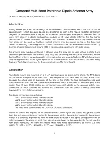
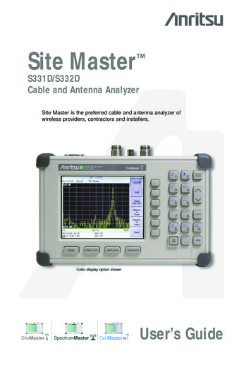
The Iota (I) AntennaA capacitive loaded and inductively center loaded vertical dipole with helicalhairpin beta match.Antenna installed at the author’s QTHThe Iota (eye-o-ta) is an inexpensive and relatively easy to build vertical dipole thatstands about 9 feet tall. It has been successfully operated on 10M through 40M. I am arelatively new HAM and overheard some members of the Tamiami Amateur Radio Clubdiscussing a similar commercial antenna, and a couple members mentioned it workedinside their large lanai enclosures. The commercial versions were too costly for thisfrugal HAM, so I decided to build one from scratch. I would like to thank all the clubmembers who encouraged and mentored (Elmered) me through this project.Construction is greatly simplified by the use of standard easily available materials, andinexpensive fittings normally used in tarp canopy support frames. The first successful
The Iota (I) Antennatransmission was made after and investment of only about 30 and 3 hours. It hasprovided hours of fun tinkering and operating for several club members.CAUTION: High voltages may be present on the antenna when operating. It mustbe located in a protected area where people and animals can not touch it.The following details should provide enough information to allow construction and tuningguidance. Further development and innovation is always encouraged.The StructureThe antenna structure is fabricated from ¾” EMT electrical conduit. Only 5 cuts arerequired from two 10’ lengths. The “T” connections were ordered on eBay (search for“”canopy fitting”).The center insulator may be the most difficult part depending on the tooling available.The initial insulator was simply a length of ½” PVC pipe reduced in diameter to slidesnugly into the conduit. This worked but was deemed too flexible for long term use.The ½” PVC pipe was then bored out to 5/8” and a piece of 5/8” hardwood dowel wasinserted through the center. This created a stiffer center insulator. A center insulatorhas also been made from solid PVC bar. The ultimate center insulator would be madefrom fiberglass, but the raw material cost would almost double the initial cost of thestructure. Reducing the diameter is the most difficult part of the project (unless youhave a friend with a lathe). Lots of small machine shops are happy to help creativepeople as long as you provide them with enough detail so they can help you in a smallamount of time.Material sources: (always verify part numbers)Conduit – Lowes part number 72713, ¾” EMT. 6 per 10’ pieceConduit Hangers – Lowes part number 75308, conduit hanger #1 size. 0.68 eachCanopy fittings – Purchased from eBay seller “buys4u”. Part numbers FTA and FOTA.Send the seller a message asking for combined shipping. The shipping fee for onepiece will cover at least four pieces. 6 each plus shipping.Solid PVC rod - MSC Industrial item number 52422920
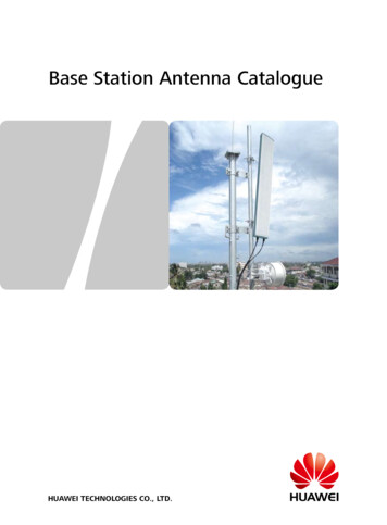
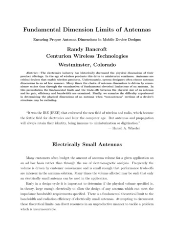
The Iota (I) AntennaCanopy Tee FittingsSee the image below for dimensions and a cut plan for the EMT.Assembly Drawing
The Iota (I) AntennaCenter InsulatorThe following lengths are cut from each piece of 10’ long conduit:Conduit 1 – 64”, 41”Conduit 2 – 37.4”, 31.5”, 31.5”The MountThe antenna should be mounted so the lower horizontal beam is two feet above theground. The mount must be nonconductive. This can be accomplished in severalways. The ultimate mount would be a piece of rigid fiberglass rod inserted into thebottom of the vertical conduit. The rod could be supported by a tripod or by a mountinserted in the ground. Less costly mounting methods are shown below.A simple PVC mounting pole can be made from 1” PVC pipe and two couplings. Onecoupling is glued to the end of the pipe and has 4 tapped holes around the perimetervery near the end. Four screws are used to center the bottom of the bottom tee fitting.The second coupling is sawed in half lengthwise, and then sawed in half crosswise.This creates two half collar pieces that are clued to the pipe just below the coupling onthe end. The purpose of the collar is to provide additional thread length for four tappedholes 2 ¼” down from the top. These screws are used to engage the conduit stubprotruding from the canopy tee. They can also be used to level the antenna a bit.An improvement on the above mounting pole is to insert a bushing with 1 1/8” ID intothe top of the coupling to eliminate the need for the centering screws at the end. The
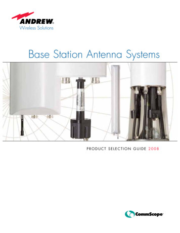
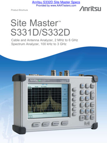
The Iota (I) Antennabushing can be a bored out piece of 1” pipe or a solid 3D printed bushing. If additionalstrength is desired around the top edge, a hose clamp can be used.Two Screw Sets MountMount with BushingA 2 foot long length of PVC pipe will be a bit flexible. To stiffen the pipe, fill it withQuikcrete or other material that will harden.A mounting pole can also be made from a surplus fiberglass antenna or tent pole oftensee at ham fests. It uses a bushing inserted in the top and the same 4 leveling screwsas above.Antenna mounted in a surplus fiberglass tent poleMounting Pole SupportThe mounting pole can be supported in a number of ways. The photo on page 1 showsa mounting pole directly inserted in the ground. A more portable mount is a
The Iota (I) Antennatripod/quadpod shown below. This wooden support was made from one 2x4 stud andone fence picket ripped down the middle. Very inexpensive.A simple wood standThe Loading and Matching CoilsNow for the more radio like part of the antenna. Also known as Voodoo.As constructed, the antenna is resonant at about 30MHz. Coils are required to makethe antenna work for amateur bands, but they can be very simple and don’t require anyheavy math or skill to make. A chart and other images below are enough information tomake coils for 40M, 20M, and 10M operation. SWR plots of tuned coils are also shownto get an idea of tuning and band width. An antenna analyzer is highly recommendedbut it doesn’t have to be an expensive one. Development and tuning was done using a 42 NanoVNA purchased on eBay. It will show return loss and SWR along with manyother parameters. The plots shown below were created by free software connected tothis analyzer. The NanoVNA (Vector Network Analyzer) is an amazing instrumentconsidering its size and cost. There are hundreds of YouTube videos demonstrating itsoperation. With the addition of a capacitor and some test leads you can even measurethe inductance of the coils you make.
The Iota (I) AntennaNanoVNACoils are mounted on coil boards that are affixed to the antenna at the center insulatorby two common conduit hangers. The hangers serve as a mounting method and alsoprovide the electrical connection from the coils to the antenna.Image rotated 90 deg.Coil board mountingCIRCUIT DIAGRAMThe photo below shows three coil boards for 10M, 20M, and 40M. The 10M board wasused to make the first transmissions and is simply a piece of ¼” plywood with an SO239connector and coils made from scrap 14GA ROMEX wire. Wire on the back side of the
The Iota (I) Antennaboard connects the coils to the upper and lower sections of the antenna by sandwichingthe wires between the board and the conduit hangers.The 40M board above is made from 1/8” thick phenolic board (MSC Industrial Supplyitem 63414544 or 63410724), and the coils are mounted in binding posts. This provedto be a very effective method for testing various coils, and coils can be tuned by simplystretching them. The 20M coils shown were initially developed on the binding postboard. They were wound tightly like an extension spring, then stretched between theposts to tune to the lowest SWR at the desired portion of the band. The photo belowshows the initial set of 20M coils on a plywood board.
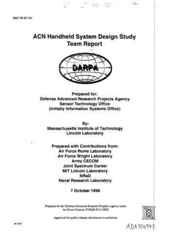
The Iota (I) AntennaPlywood is not a recommended material for long term use. Wood compresses and willeventually cause the posts and connections to the antenna to become loose.For tightly spaced coils, enamel coated wire is necessary.Below is a chart showing the characteristics of some coils as a starting point. All ofthese coils have been used successfully. Note that when tuning the coils the top andbottom coil must be tuned the same, as closely as possible. While the idea of bendingtwo coils to be exactly the same seems a bit ridiculous, stretching two coils to the samelength is a bit more practical. All the coils in the chart use 14GA wire.Below are some SWR plots of the various coils. As frequency goes down, thebandwidth decreases, as is typical for a coil loaded short antenna. This makes itnecessary to tune the coils to the part of the band of interest.10M Band
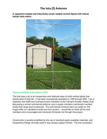
The Iota (I) Antenna10M Band20M Band
The Iota (I) Antenna40M BandBelow are some drawings with dimensions for the coil boards.The binding post board
The Iota (I) AntennaThe 20M fixed length coil boardFeedline and PlacementThe feedline used for development was about 80’ of old RG8. From the connection onthe antenna, the feed line slopes to the ground at about a 45 degree angle. No Balun isrequired. All measurements were taken at the radio end of the feedline.The antenna should be placed as far away from other structures as possible.Relocation may require retuning. This antenna has only been tested up to 100W.Some modifications may be necessary for use above 100W.CAUTION: High voltages may be present on the antenna when operating. It mustbe located in a protected area where people and animals cannot touch it.Future DevelopmentFuture areas for development include: A multi band coil board Remote band switching Remote band tuning
The Iota (I) Antenna Dimensions for resonance at 10M without coilsOperating Observations“How good is it?” is a very subjective question. Without extensive and expensive testinga true quantitative answer is not possible. From Florida, it has been used to make FT8contacts from New Zealand to Ukraine. It compares about equally to an end fed halfwave installed at about 25’ elevation. Sometimes better. Sometimes worse. Manyfactors will affect its performance including proximity to other things, feed line, bandconditions, spousal complaining, cosmic rays, etc. There have been some reports of itworking within a large lanai (HOA friendly). Our club conducted an antenna shootout ata local park. The entries included this antenna as well as two generations ofcommercial versions like it. The judges declared this antenna to be just as good as thecommercial versions!Build one ant try it! Birds love it too.Added capacitanceThe author, publisher, distributor, and purveyor of these plans cannot be responsible for the accuracy of the plans, drawings, technical data orinformation contained in these plans, and the reader makes use of such at his own risk. None of the statements made or information containedherein shall create any warranty, expressed or implied, nor that any of the various devices, plans, drawings, mechanical or electrical systems ordata shall be fit or useful for any particular purpose. The statements contained in these plans are informational only and not made or given as awarranty of the data in any way. The reader shall be solely responsible for determining the accuracy and adequacy of the data for any and alluses to which the reader shall apply the data. Keep safety in mind at all times. Read and understand operating instructions and safetywarnings of all tools, machinery and radio equipment.
A mounting pole can also be made from a surplus fiberglass antenna or tent pole often see at ham fests. It uses a bushing inserted in the top and the same 4 leveling screws as above. Antenna mounted in a surplus fiberglass tent pole Mounting Pole Support The mounting pole can be