Transcription
1Substation Testing and Commissioning: Power Transformer Through Fault TestM. Talebi , Member, IEEE,Power Grid EngineeringY. Unludag†Electric Power SystemAbstractThis paper reviews the advantage of performing transformer through-fault test in substation testing and commissioning prior to theactual energization in addition of theory of testing and numerical procedure. This test allows the engineer and relay technicians tovalidate all the CTs and PTs secondaries, transformer winding configuration, protective relays and wiring correctness and circuit.The value and benefit of performing this test is also shown in real world project.Index TermsTransformer, Through-Fault, Substation, Commission and Testing.I. I NTRODUCTIONSubstation commissioning and testing is a critical task prior to substation energization to ensure all equipment will functionsafely in the intended manner. Medium and large power transformers in distribution or transmission power system are oftenprotected by differential relay because of its high sensitivity and fast operation. The principal and design of transformerdifferential relaying has been covered and described in many literature and manuals and it is not the scope of this paper[1]–[4]. After design and installation of transformer differential relay, it is essential to prove and validate its circuit prior tosubstation energization. An incorrect wiring of the differential relaying will cause false operation or no operation of protectiverelays during normal or fault event. Several incidents have been reported by the U.S power utility system regarding improperwiring and circuit of CTs in power transformer protective relaying which has resulted in transformer protection mis-operationswith short and long-term impact and consequences [2]. It is still a common practice in the U.S. utility system to defeat thetransformer differential relay function before connecting it to the load and performing the in-service test to verify its circuitafter the actual substation energization. It is clear that validating all protection circuits and discovering all potential errors priorto substation energization, without disabling the relay function, is highly desirable. As such, in this paper, a detailed procedureof the through-fault test for power transformer differential circuit prior to substation energization using the practical examplesis covered. This practical commissioning test was developed decades ago and the authors are simply presenting the theory andprocedure of how the test performs in the substation.The reminder of the paper is organized as follows: Section II reviews the through-fault test application and advantages. The testand numerical calculation procedure is presented in section III. Section IV discusses performance and results of through-faulttest with real world example and section V concludes the paper.II. P RELIMINARYIn the power transformer protection, through-fault is the system fault that are external to the transformer protection zone. It isa well known concept that the zone of the protection in transformer differential relay will be defined by the location of theCTs secondaries. Through-fault test apply the balance three phase voltage, equal voltage magnitude and displaced 120 degreeamong phases, on one side of the transformer or circuit breaker. Since the circuit is balance, transformer positive sequenceimpedance will be in series with positive sequence voltage and current of test source and circuit will complete its currentloop by shorting and grounding all bushings outside the differential relay zone of protection. Through-fault test will provethe CTs polarity are correct and the expected direction of secondary current flow is correct for a given direction of primarycurrent flow. It will also simply confirm the transformer CTs ratio by proving that the ratio, as installed, is as specified andlisted in the drawing and transformer’s nameplate, and if taps are available, that they also have the correct ratio and have beenwired to the correct terminals. Furthermore, it is a useful test for verifying power transformer winding connections and phasedisplacement corresponding to its vector group on the nameplate in the field. Depending on phasing connection, this phaseshift may be either plus or minus 30 degree from primary to secondary for positive sequence voltages and currents. It willalso confirm protective relaying wiring correctness. Potential transformers secondaries can also be checked during this test.M. Talebi is a Filed Service Engineer with Power Grid Engineering, Orlando, FL.Email: mktalebi@powergridmail.com (corresponding author)
2It should be noted that all other protective relays in transformer protection design scheme such as 50/51 can also be testedduring through-fault testing.III. T EST P ROCEDURE AND N UMERICAL C ALCULATIONPrior to the test, transformer differential protection zone should be identified based on the relay functional drawing. Expectedtest current value and phasor diagram should be computed before running the through-fault test. The test source voltage,transformer and CTs winding connections, transformer impedance, transformer power capacity and its tap position under thetest, system phase rotation, phase-to-bushing connections, and CTs and PTs ratios are required for the calculation procedure.It should be noted that the size and output voltage of temporary generator required in the filed as a test source voltage willbe determined after calculating the current flow through the circuit. Based on the microprocessor protective relays manual,a minimum secondary current of 0.25 amps is required to pass the pickup and accuracy range of the digital relays. Hence,sometimes transformer size and its impedance make it difficult to choose the temporary generator used for through-fault testin the field to push the minimum required current. Practically, the common temporary generator output voltage used in thefield is at a maximum of 480-500 VAC with 125 KVA.A. Calculation ProcedureTest source voltage will be in series with positive sequence impedance of the transformer; therefore, eq. 1 is for calculatingthe p.u. value of the injecting current by test source [5], [6],IGp.u. VGp.u.Zxf mrp.u.,(1)where IGp.u. , VGp.u. , and Zxf mrp.u. are p.u. the values of the test source current, test source voltage, and transformer impedancerespectively.For calculating the VGp.u. , simply use the p.u. equation of,VGVGp.u. VBase(2),where VG is the output voltage of the test source voltage and VBase is the voltage of the transformer side (usually the lowside) the test source is connected to.Now, by applying the three phase power equation, we can calculate the transformer low and high side Base currents,MV A3VHxf mr(3)MV A,3VLxf mr(4)IHBase ILBase where VHxf mr , and VLxf mr are the high and low side of the transformer voltage in KV and M V A is the power capacity ofthe transformer on the tap under the test.Finally, by applying eq. 5 and 6, we can calculate the current flow through the transformer primary and secondary siderespectively,IHxf mr IGp.u. IHBase ,(5)ILxf mr IGp.u. ILBase .(6)The magnitude of the current in the CTs secondaries can be calculated by dividing current magnitudes calculated in eq. 5 and6 to CTs ratios.
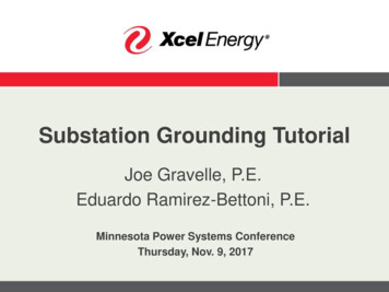
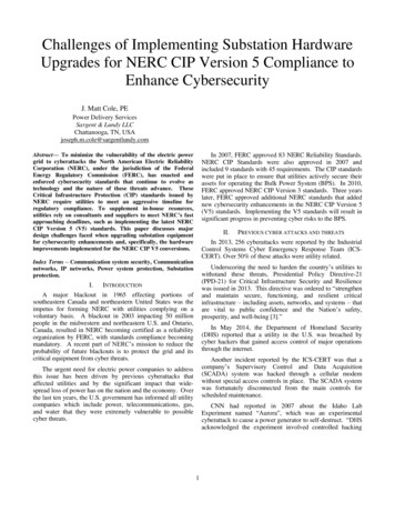
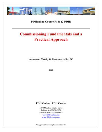
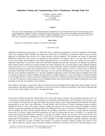
3Fig. 1. Simplified Single-Line Diagram.TABLE IC URRENT M AGNITUDE AND P HASE A NGLE OF CT S FROM F IG . 1CurrentIGICT 1ICT 2ICT 3ICT 4ICT 5P haseAIG ]270IGCT1 R ]270IGCT2 R ]1200]0IGCT4 R ]300IGCT5 R ]120P haseBIG ]150IGCT1 R ]150IGCT2 R ]360P haseCIGp.u. ]30IGCT1 R ]30IGCT2 R ]240IGCT4 R ]180IGCT5 R ]360IGCT4 R ]60IGCT5 R ]240For measuring the phase angle in the CT secondary, a known phase voltage (usually phase A with zero degree phase angleof test source) should be chosen as a reference. The inductive nature of power transformer in addition to phase displacementbetween transformer’s winding has to be considered for CTs secondaries phase angle measurement. Fig. 1 shows a basicsubstation one-line diagram. For simplicity, lets just assume that transformer differential relay zone is from CT 1 to CT 2. Testsource is connected to the low side of the transformer and as shown, bushing on the line side of the circuit breaker has beenshorted and grounded. Phase A current out of test source lags 90 degrees the reference voltage, VA ]0, and measures Ia ]270.Looking to Fig. 1, this current will enter to the polarity side of CT 1 in primary side of power transformer and will havesame phase angle with lower current magnitude depending to CT 1 ratio. On the secondary side of the transformer, phase Acurrent enters to non-polarity side of CT 2 and it should measure IA ]120 in Wye connected configuration CT secondary seenin microprocessor differential relay (transformer 30 degrees phase shift plus 180 degrees is experienced from the mirroredpolarity of both winding CTs). It is essential to know how the phase angle meter display has been programmed i.e. if it isin leading or lagging operation state. Reading above is for the meter programmed in leading operation state which means thevalue displayed is the number of degrees by which the current leads the voltage. If the meter has been programmed in laggingoperation state, the meter will display Ia ]90 and IA ]300 for CT 1 and CT 2 respectively.Fig. 2 shows the expected phasor diagarm of voltage and current for standard Delta-Wye transformer differential circuit. Byselecting phase A voltage, VA ]0, as a reference, phasor diagram of voltage and current of test source connected to Wye sideshould be expected as Fig. 2(a). Remember that the power transformer is considered as an inductive load and current lagsvoltage by 90 degree. In practical power transformer there is always resistive component so there will be 3 5% difference fromthe expected value. Fig. 2(b) shows the phase angle relationship between CTs secondaries on both sides of the transformer,CT 1 and CT 2. Again, it should be noted that the angles are measured by using temporary generator phase A voltage as areference. The magnitude of phasors shown in the Fig. 2 is arbitrary and purpose is just showing the phase angle relationship.Table I summarized the expected values for CTs magnitude and phase angle corresponding to Fig. 1 with phase angle meterin leading operation state.B. Testing ProcedureHere are the steps should be taken in the field for performing the through-fault test:1) Prior to performing the through-fault test, it is important that all safety procedures regarding the switching, locking, andtagging be observed and formalized to avoid the protection engineers and technicians from being exposed to substationequipment that has not been properly de-energized.2) Location of connecting the test source in one side and shorting and grounding of bushing on the other side of protectionzone based on the relaying functional diagram and substation layout has to be identified.3) Primary conductors and phasing needs to be visually proven and identified to have a correct phasing prior to the test.4) Temporary generator phase rotation needs to be verified before the test.
4(a) Phase angle relationship between testsource voltage and current in primary sideof Transformer(b) Phase angle relationship between current in CT 1 and CT 2 seen by protectiverelayFig. 2. Expected Phasor Diagram of Fig. 1.5) Generator current magnitudes need to be known and a phase reference needs to be established in order to analyze thereading. Current can be measured using a clamp-on ammeter and compared with the first CT calculation in calculationsheet. Phase reference is chosen to prove correct phasing and polarity of all CT circuits to be tested and it can be phaseA to ground voltage of the temporary generator. All the phase angle readings during the test will be based on the chosenreference. Therefore, engineer or technician needs to have extended test leads to go from reference point to all measuringpoints.IV. P RACTICAL E XAMPLE C ASE S TUDYA real world project with expected and measured values under the test is covered and illustrated in this section to show theeffectiveness of the testing method.A. Solar ProjectFig. 3 shows the modified single line diagram of a 50 MW solar project. The GSU transformer nameplate information wereas follows: 3 phase, 24/32/40M V A, 115/34.5KV Delta-Wye two winding configuration. The impedance of the transformerunder 24M V A was measured as %7.33 and transformer was under 115 KV tap. The transformer differential relay zone ofprotection starts from CTs on the line side of breakers 52-1 and 52-2, CT 4 (600/5 tap) and CT 3 (600/5 tap) and goes to lineside of transformer breaker, 52-21, CT 1 (300/5 tap). CT1 and CT2 are 115KV line side CTs of main circuit breaker, CT3and CT4 are 34.5KV line side CTs of feeder breakers.Through-fault test was performed at solar substation by connecting a 3-phase 500V generator to the line side disconnects ofeach 34.5 KV feeder and applying shorts on the line side disconnects of the 115 KV circuit breaker. Prior to the test, expectedvalues for current calculated as follows by applying equations (1)-(6):VGp.u. 500 0.014434.5KV(7)
5Fig. 3. Modified single line diagram of solar project.0.0144 0.1970.073324M V AIHBase 120.49A3115KV24M V AILBase 401.64A334.5KVIHxf mr 0.197 120.49 23.73A(11)ILxf mr 0.197 401.64 79.41A.(12)IGp.u. (8)(9)(10)Applying CT 4 and CT 3 ratio of 600/5, current magnitude in the secondary is 0.66A. For the PT located in 34.5KV bus,P T 1, with 19900/120 ratio, the expected voltage magnitude in PT secondary can be calculated asVP T 288 1.74V165.8(13)After calculating expected values, voltage and current readings were taken on each CT and PT circuit to validate CT and PTwiring and relay settings. Table II shows the expected values vs. measured values of CTs circuits. The phase angle meter wasin lagging operating state. During final walk through before the testing started, it was discovered that several CT shortingscrews were not removed and CT tap ratios did not match the single line. After these issues were corrected, the testing started.During the test it was discovered that A and C phase wiring on all CT and PT circuits were rolled and CT connections shownon the single line were connected to the wrong relay windings. As shown in the table II, the expected value of phase Acurrent was 0.66]90 but the measured value was 0.66]327 which was the expected value of C phase. It was also discoveredthat the differential relay CT connection compensation settings were set wrong. Winding 2 CT, CT 4 and CT 3, connectioncompensation setting was set as 1 where it should have been 11 to compensate 30 degrees phase shifting from low to highside, meaning Wye side leading Delta side by 30 degree.TABLE IIM AGNITUDE AND P HASE ANGLE OF C URRENTS OF S OLAR FARM P ROJECT- E XPECTED V.S. M EASUREDCT SCT1CT2CT3CT4Expected ValueAφBφ0.397]300 0.397]600.397]300 0.397]600.662]90 0.662]2100.662]90 asured ValueAφBφ0.385]177 0.388]580.383]176 0.388]580.66]328 0.65]2080.66]327 0.65]207Cφ0.388]2970.389]2970.67]880.67]87
6After this discovery, wiring for CTs and PTs were corrected and tested again to confirm the correctness of the circuit.V. C ONCLUSIONIn this paper, the theory, application, and advantages of transformer through-fault test in substation commissioning was covered.Through-fault test employs a temporary generator as a three phase test source to inject three phase balance currents into thepower transformer windings and its CTs; therefore, allowing the engineer and relay technicians to measure current and voltagemagnitude and phase angle in the CTs and PTs secondary and protective relays. The test will check the integrity and correctnessof the circuit and will discover incorrect wiring, polarity, and setting prior to actual energization. This gives enough time torelay technicians and engineers to troubleshoot the circuit and take necessary corrective actions.VI. ACKNOWLEDGMENTThe authors would like to thank Duke C. and M. engineering and technicians team for their inputs, specifically Rick Jonell.VII. R EFERENCESR EFERENCES[1] C. L. Headley, “Differential Relay Sensitivity Adjuster,” IEEE Trans. American Inst. of Electrical Engi., vol. 69, pp. 1203-1206, Jan. 1950.[2] D. Costello, “Lessons learned through commissioning and analyzing data from transformer differential installations,” Power Sys. Conf.: AdvancedMetering, Protection, Control, Communication, and Distributed Resources,, Clemson, SC, USA, March 2007.[3] ABB Group, “Differential Relays for Protection of AC Generator, Transformer and Station Bus,” Application Data 41-301E, Coral spring, FL, Apr.1991.[4] Z. Gajic, “Differential Protection for Arbitrary Three-Phase Power Transformers,” Department of Industrial Electrical Engineering and Automation ,Lund University, Sweden, 2007.[5] P. Kundur, N. J. Balu, M. G. Lauby, “Power system stability and control,” McGraw-Hill, Jan 1, 1994.[6] Duke C. and M. Engineering Group, “Relay Construction and Maintenance Process for Verifying CT Circuits using the, Through Fault Test Method,”TECP-CNST-TRM-00117, Raleigh, NC.
In the power transformer protection, through-fault is the system fault that are external to the transformer protection zone. It is a well known concept that the zone of the protection in transformer differential relay will be defined by the location of the CTs secondaries. Through-fault test