Transcription
INSTALLATION INSTRUCTIONSHUSTLER 4-BTV, 5-BTV TRAP VERTICALWARNINGINSTALLATION OF THIS PRODUCT NEAR POWER LINES IS DANGEROUSFOR YOUR SAFETY, FOLLOW THE INSTALLATION DIRECTIONSGENERAL DESCRIPTION:The Hustler 4-BTV is a four-band trap vertical antenna providing an omni directional pattern.The 4-BTV is designed as a self-supporting vertical to provide optimum operation in the10,15, 20 and 40 meter bands. It can also be adapted to operate in the 75 meter band. Thisantenna is designed for installations with restricted space.The Hustler 5-BTV is a five band trap vertical antenna adding 75/80 meter operation to the4-BTV. This is achieved by adding the RM-80S resonator and 4457-1 spider assembly(see diagram page 3).The Hustler 4-BTV provides electrical selection of bands through the use of optimum Q traps,which are individually and precisely tuned and internally sealed at the factory. The traps areparallel tuned circuits, which provide efficient isolation between the vertical sections,permitting the multi-band operation. Broadband operation over the entire ham band at verylow SWR’s is possible in a proper installation. Operation in the 75/80 meter band is providedby installing the appropriate resonator on top of the 4-BTV.The Hustler 4-BTV was designed to provide optimum performance from both an electricaland mechanical standpoint. Mechanically, this antenna boasts a heavy duty base and heavyduty aluminum tubing. The mechanical assembly is accomplished with all stainless steelhardware. The use of clamps permits readjustment if necessary, and allows individualpeaking of each band. The mechanical construction is such that guying is not ordinarilyneeded. If the 75 meter resonator is attached to the 4-BTV, it may be desirable to guy theantenna above the 20 meter trap with small diameter polypropylene rope.The performance provided by the Hustler 4-BTV is better than any other antenna of this type.Broad banding is such that one measurement and setting permits both phone and CWoperation. The antenna provides a nominal 52 ohm base impedance when installed andtuned according to the instructions. The radiation efficiency is equivalent to, or greater than,other trap verticals.STEP-BY-STEP ASSEMBLY:1. Check the parts against the package contents listed on the following page.2. Install mounting bracket on the support mast or stake. Tighten “U” bolts securely.Uselock washers and 1/4”-20 hex nuts (heavy nuts). Use 1-1/4” I.D. water pipe or othervery strong support.3. Accurately cut radial lengths (if needed or desired) in accordance with radial lengthtable (Fig. 6)
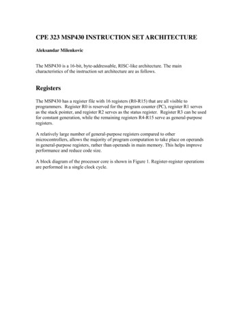
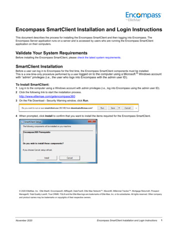
PACKAGE CONTENTSQty.111211161Part Number4098-1Bracket Assembly4190Top Tube Section4087-1Lower Tube Section4087-2Intermediate Tube Section4090-1Ten Meter Trap4090-2Fifteen Meter Trap4090-3Twenty Meter Trap5481Spider Tubes4198Accessory Kit Consisting of the Following:72411174116271IN PLASTIC BAG3152-4Clamp, #12, SS3488-6"U" Bolts2491-5Lock washers 1/4" Split3609-5Spider Hub2194-15 Screw 6-32 x 3/4"2382-1Nut Hex, 10-32 SS2832-31 Nut Hex, 6-32 SS2832-32 Nut 1/4-20 x 7/32" Thick4513Terminal Lug 1/4" Hole4514Terminal Lug #10 Hole3162-9Flat Head Screw 6-32 x 5/8"2233-41 Washer 1/2" O.D. x 3/16" I.D.2381-16 Lock washer Ext. #6 SS6099Danger Label2822IN PLASTIC BAG FOR RADIAL MOUNTING2700-7Hex Head Bolt 1/4-20 x 1-1/2"2233-16 Washers 5/8" O.D. x 1-1/4" I.D.2491-5Lock washer 1/4"2832-32 Nuts 1/4-20 x 7/32" Thick4260-1
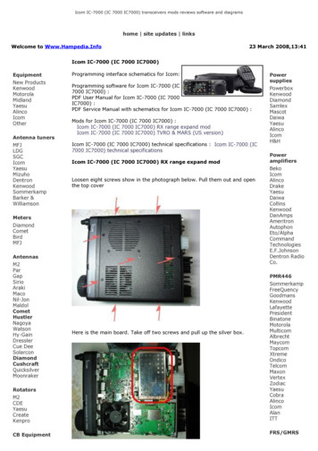
4260-1Plastic Cap5303-1Three BladedSpider Assembly4457-1(RM 75/80SResonator)5-BTV onlyStud 5648For 75 MeterResonatorSpider AssemblyScrew3162-9 (6)Spider Tubes5481 (6)Top TubeSection 4190 1-1/4" x 56"Spider Hub3609-5Plastic Cap 4082Nut 2382-31(1)Lockwasher2381-16 (1)Alum. Tube andPlug Ass'y4100Insulator 4478Lockwasher2381-10 (6)Screw 2194-15Screw 2893-7 (3)Washer 2233-48 (3)Gasket 9433U-Bolt3488-6 (2)Lockwasher 2491-5 (2)Nut 2382-32 (2)Screw 4405-1 (3)Lockwasher 2381-10 (1)Washer 2381-10 (3)Nut 2382-1 (3)Bracket 4342-220 Meter Trap4090-3 GREENClamp 3152-4 (7)IntermediateTubeSection 4087-2Plastic Cap 408215 Meter Trap4090-2 REDFactory Adjusted TrapsDo Not Loosen ClampsIntermediate Tube Section 4087-21-1/4" x 20"Plastic Cap 408210 Meter Trap4090-1 ORANGELockwasher 2491-5 (2)Lower Tube Section 4087-1Nut 2382-32 (2)Insulator 3002Lockwasher 2381-10 (1)Nut 2382-1 (3)Washer 2233-41 (2)Lug 4514Washer 2233-41Lockwasher 2381-10 (2)Nut 2382-1 (1)Washer 2233-33 (2)Lockwasher 2491-5 (1)Washer 2233-33 (1)Lug 4513WasherWasher 2233-16 (8)2233-33 (1)LockwasherScrew2491-5 (2)2893-13 (1)Nut 2382-32 (2)Radial TerminationsBolt 2700-7 (2)
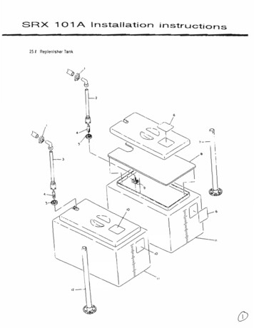
Recommended Method of Preparing Coax20 Meter Trap6-32 x 5/8” Screw (6)Nut 2382-1 (6)Separate strands of braid with an awlbeing careful not to break any.Figure 2Figure 3Lug with1/4” dia.hole onside.Draw center conductor outwith an awl or dull pointedinstrument.Lug with 3/16”dia. Hole onshield end.Solder on the sizelugs as indicated above.Tape tightly with plasticelectrical tape.After installing coat with sealantFigure 4Figure 5ThisD”Surfacemust beUP3/8” dia. X 13”Alum. Tubes (6)No. 6-32 x 3/4” ScrewNut 2382-14260-1
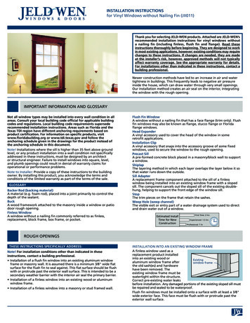
Figure 6Illustrations Showing FeedLine and Radials ConnectionsRadials(not supplied)Radial Length Table1/4-20 x 1-1/2hex head bolts4 washers 5/8 o.d.1 lockwasher 1/4"1 hex nut 1/4-20Radial Lengths for4 Band Operation2 Each Required10152040MetersMetersMetersMeters8' 4"11' 4"16' 4"32' 4"Radials(not supplied)Lock washer #2491-5Washer 1/2" O.D. x3/16" I.D. (6)ShieldThick Hex Nut1/4 - 20x7/32Lockwasher #2491-5Nut 2382-1 10-32 (3)Hot4260-1ShieldHotWasher #2233-33Screw #2893-13
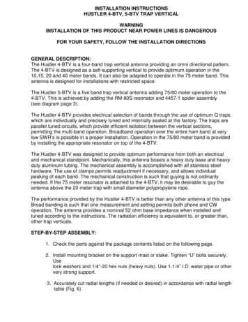
Figure 7Dimensions A,B & Care measured fromthese pointsDMeasured from topsurface of spidercasting to top ofcap on tube20 Meter TrapC20" TubeC15 Meter TrapB20" TubeBNever loosenthe trap clamp10 Meter TrapADimension TableApproximate dimensionsAB2 - 1/821 - 7/8 61-1/8On a metal tower withradials dropped 45 degrees221 - 1/8 61-1/8On ground with radials1On ground without radials0Type of InstallationOn a roof with 4 footpipe and radials4260-1CD72" TubeA1 - 5/8 1 - 1/16 62-1/81/21 - 1/16 62-1/8The above dimensions are in inches.Tuning may be necessary to obtain resonance at desired frequency.4"
4. Prepare split lead on coax in accordance with Figure 2 and 3. RG-8U coax is recommended.5. Install lugs on coax as shown in Figure 4 and weatherproof with electrical tape.6. Install coax feed line and radials as shown in Figure 6.7. After making all connections to the mounting bracket, a heavy protective coating such as Krylonclear spray would be very advantageous.8. Assemble the 3/8" x 13" tubes to the hub as shown in Figure 5, using the 6-32 machine screws,number 6 lock washers and the 6-32 hex nut.9. Install the 10 meter trap to the 1-1/4" x 72" tube, using one of the clamp assemblies. Set todimension A and table in Figure 7, the measurement should be made at the end of the long tube andthe bottom edge of the trap. Securely and carefully tighten the clamp.IMPORTANTTHE PLASTIC CAP IS THE TOP OF THE TRAP AND MUST BE INSTALLED IN THATPOSITION, THE CLAMP AT THE BOTTOM OF THE TRAP SHOULD NOT BELOOSENED. THIS WOULD UPSET TRAP CALIBRATION.10. Install #12 clamp at each end of one of the 1-1/4" x 20" tubes and slide over the tube of the 10 metertrap. Install the 15 meter trap in the opposite end of the same tube and set both dimensions B fromtable in Fig. 7. The measurement should be made from the upper most edge of the plastic cap to thebottom edge of the 15 meter trap. Securely tighten clamps.11. Install the second 1-1/4" x 20" tube, complete with clamps, on the 15 meter trap and then install the20 meter trap in the top of that tube. Set to dimension C from the table in Fig. 7, again measuringfrom the top of the plastic at the bottom of the tube, and from the top of the tube to the bottom edgeof the trap.12. Install spider assembly as shown in Fig. 5, it should be flat against the top of the 20 meter trap cover.Securely tighten the 6-32 x 3/4" screw with lock washer and hex nut.13. Install the 1-1/4" x 56" tube to the 20 meter trap and set to dimension D from table in Fig. 7.Securely tighten clamps.14. Each clamp should be installed near the edge of the tubing to obtain the best mechanical andelectrical connection. Re-check all bolts to insure tightness. Re-check all dimensions against table inFig. 7.15. Install assembled antenna on mounting bracket and set the bottom dimension A, from table in Fig. 7,and securely tighten clamps. Never allow the mast on which a 4-BTV is mounted to extend abovethe bracket.4260-1
INSTALLATION:READ THE ATTACHED SAFETY WARNING ON LAST TWO SHEETS BEFOREPROCEEDING FURTHERAn important part of any vertical antenna is its ground plane. While the Hustler 4-BTV was designedas a space saver, we recommend one of the following installations from a performance viewpoint.1. For optimum performance, roof mount with radials. Roof mounting of the antenna will provideheight which, in turn will generally provide better transmission and reception.The 4-BTV can be mounted on a ground mounted tower, heavy duty chimney clamp, woodenpole, short roof mounted tower or other suitable support assembly. Try to locate the antenna10-15 feet away from non-metallic structures.CAUTION: Mounting the 4-BTV on towers, tripods, or large mast pipes, approximately aquarter wave in length, can often provide an upset to the counterpoise created by the radialsystem, and act as a vertical dipole instead of the desired ground plane. To correct thisproblem, the radial system must be R.F. isolated from the mounting structure. This may bedone by using a non-conductive mounting mast, such as heavy wall fiberglass tube orfiberglass rod or by sliding a split piece of PVC pipe over the metal mast. The coax ormounting bracket should not be directly grounded.The 4-BTV installation is most easily accomplished by installing the base only to your supportassembly. After connecting radials and feedline to the base, the 4-BTV can be attached to thebase.Using the radial length table (Fig. 6) install two insulated wire radials for each band used. It isrecommended that the radials be constructed of large diameter insulated wire, 14 gauge isusually ample.When radials are installed they should be equally spaced around 360 degrees with radials ofequal length opposite each other. Never bunch radials as one will detune the other. They shouldbe attached to the base mount in accordance with Figure 6.Care should be taken to make a good electrical connection at the antenna bracket. When radialsare used in a roof mount configuration, every attempt should be made to permit a 45 degreedroop angle below horizontal.This is accomplished by choosing a mounting pipe or short tower long enough to make theseangles possible. If space is limited, some compromise is permissible providing the droop angleis held between 10-60 degrees below horizontal with radials fanned out as much as possible.If space is severely restricted, radials may be zigzagged or run in an "L" configuration avoidingnear parallel wrap back less than 90 degrees.4260-1
1. The importance of the ground system cannot be over-emphasized. The ground or radialsystem must be considered as half the antenna.When radials are used, high impedance will exist at the ends of the radials, and adequateinsulation must be provided, or their purpose will be defeated. Tie them off using a nonconductive material such as polypropylene rope or heavy gauge fishing line. In a casewhere the antenna or the radials are mounted over or near metallic objects the radialsmust be insulated or mounted at least 4 in. over the roof.2. Second Choice, ground mount with radials; if you are unable to mount the antenna in thepreferred roof mount configuration, the second best choice would be that of groundmounting. In ground mounting it is important to choose a location reasonably free fromobstructions such as houses, metal fences, trees, wires, vertical downspouts, aluminumsiding, other antenna, etc. Try to maintain at least a radius of 10-15 feet of clear areaaround the antenna. It is recommended that the 4-BTV be mounted on a 4 foot metalstake such as a 1-1/4" I.D. Water pipe. Do not exceed this length. This stake should beburied in the ground with 18 inches left protruding. (Do not concrete or put into a pre-dughole. Drive it into the ground.) Position the 4-BTV base on this pipe to a location notexceeding four inches of separation between earth and coax connection. Do not try to usea network of ground rods around the base of the antenna. If the ground supplied by thispipe is not sufficient, radials must be employed.The radials in this type of installation will provide a better overall performance than thatof stake mount only. Ground mount radials may be either buried a couple of inches belowthe surface or left on top of the ground. If they are left on unburied, power equipment(such as lawnmowers) or pedestrian traffic could become entangled in the wires.Using the radial length table, Fig. 6, install two insulated radials for each band. It isrecommended that the radials be constructed of large diameter wire; #14 gauge is usuallysufficient. The radials should be spaced around the base 360 degrees with radials of equallength opposite each other. Never bunch radials, as one will detune the other. Theyshould be attached to the base mount in accordance with Figure 6. Any wire droop on theground need not be of concern.Least Desirable, ground mount without radials. If you do not have sufficient space and areunable to use a ground radial system, ground mounting of the antenna on a 4 foot ground stakedriven into the ground with only 18 inches protruding, will provide good performance, which inturn, will be in direct ratio to the ground conductivity and soil conditions in your particular area.In ground mounted location, performance (SWR, bandwidth and radiation efficiency) is directlyrelated to ground conductivity. If the ground conductivity is good, you obviously will obtainbetter results. As stated previously, the 4-BTV was expressly designed to give you satisfactoryperformance even in this configuration. Therefore, if ground mounting without radials is anecessity, you can still obtain better performance from the 4-BTV than obtainable from anysimilar antenna.NOTE: Adding more pairs of radials than the 2 per band prescribed in instructions, may result inobtaining better results for DX'ing.4260-1
Favorable soil conditions can be a reason that sometimes a ground mount using the soil as aground plane may result in better DX'ing than a roof mount using only a pair of radials perband.TUNING FOR ALL CHOICES:The dimensions given in the table are approximate and will vary, depending on environment. To checkantenna tuning, use a sensitive SWR bridge. (DO NOT USE A FIELD STRENGTH METER.) Usingonly sufficient power to obtain a full scale reading, check and record the SWR at the high, center andlow edge of the bands. If the SWR reading is lowest at the high end, lengthen the related section of theantenna; if it is lowest at the low end, shorten this antenna section. Always attempt to get the verylowest SWR reading in the center of the band. Tuning in this manner will permit operation in both thephone and CW portions with a low SWR. If you favor one end of the band or the other, you can retunethe antenna to provide the lowest SWR in that portion, if desired.In the process of tuning the antenna, it is mandatory that you always start with 10 meters and workyour way up the antenna. Tune 10 first, then 15, 20 and 40 meters. Any adjustments made on 10 willaffect the other bands. Any adjustment made on 15 will affect 20 and 40. By the same token, anyadjustments on 20 will affect 40. Adjustment of the individual bands is as follows: 10 meters, adjustdimension A; 15 meters, adjust dimension B; 20 meter, adjust dimension C; and 40 meters, adjustdimension D.It is not necessary to remove the bracket each time to adjust the antenna. It is only necessary to removethe antenna from the bracket. (If the desired SWR cannot be achieved, it is probably because of aninsufficient counterpoise system or poor soil conditions.)If resonance can be adjusted properly but a low SWR cannot be reached, then it is probably due toinsufficient insulation at the ends of the radials, improper angle of the radials, or reflections fromnearby resonant objects. A number of conditions may cause the resonance to shift from the factorydimensions occasionally to the point that resonance cannot be reached within the normal range ofadjustment; lengthening or shortening the radials may help to compensate for these conditions.Changing coax length or adjusting a tuner may make the SWR appear better but will not change theantenna, the final radiator, or its performance. When the antenna is tuned properly at resonance, littlechange in SWR will occur regardless of where the bridge is located in the line.Never use an antenna tuner to tune the 4-BTV. Proper tuning of this antenna requires the 4-BTVsections. Use of a tuner only fools the transmitter and does not correct a problem at the antenna. Theantenna system must be tuned properly at the antenna to radiate efficiently.Filters should never be used in a coax line while trying to tune an antenna.4260-1
1ADDING 75/80 METER CAPABILITY1. With reference to Figure 7, mark the location at the bottom of the dimension “A” and removethe 4-BTV from its base by loosening the lowest stainless steel clamp.2. If your installation is elevated, two radials are required at the following lengths. If space isrestricted, radials may be zigzagged or run in an “L” configuration avoiding near parallel wrapback. Phone Band: 75 meter resonator – 64ʼ 4”, CW Band: 80 meter resonator – 65ʼ 6”.3. Install a spider assembly, part #4457-1, after bending the three spider arms as illustrated inFigure 1 on the top of the 56” upper tube section just below the 75 and 80 meter resonator.4. Determine and set approximate tip rod length from Figure 8 for your desired band location.Tighten tip rod locking nut securely and attach resonator to 4-BTV.5. Replace the 4-BTV on the mounting bracket to its original “A” dimension.6. Check performance with SWR bridge. Minor adjustment (lowest SWR) may be required on thetip rod length to establish resonance at the desired 75 or 80 meter frequency.7. Reactance of the resonator may cause slight change in 40 meter resonance. This is easilycorrected by adjusting element dimension “D”, Figure 7.TIP ROD LENGTHS FOR 75 OR 80 METER RESONATORS USED WITH 4-BTVTip rod length measured from top of tip ball down to top of clutch locking nut as illustrated.NOTE: All resonators are supplied with tip rod lengths for mobile operation. With the 4-BTV, ashorter length is required, therefore, remove the tip rod from the resonator and grind off the necessaryamount from the end that inserts in the resonator. Before cutting ascertain the approximate rod lengthfrom the chart plus no less than 4 inches for insertion in the upper tube section of the resonator.DIMENSIONS INDICATED ARE APPROXIMATEFREQUENCY (KHz.) ”26-3/4”(Novice Band) (Novice he above dimensions are exposed lengths of tip rod.4260-1Tip RodLengthAdd 4” forTip Rod Insertioninto Tube
GUYINGThe 4-BTV is designed as a self-supporting vertical. However, if your area encounters severewind velocities or icing conditions, simple guying will prevent the possibility of failure.Attach a small diameter polypropylene rope just above the 20 meter trap. The polypropylenerope should ultraviolet (UV) stabilized and weather resistant. Guying should be tightened justenough to permit the antenna to swing in a two to three degree arc. If a 75 or 80 meter resonatoris included in your installation, use guying.RADIALSRadials should be made from insulated wire of #14 gauge or larger, insulating the bare ends of wireon the outer end of the radials. A minimum of two radials per band is required.RADIAL LENGTHS ARE AS FOLLOWS10 Meters8' 4"15 Meters11' 4"20 Meters16' 4"40 Meters32' 4"75/80 Meters 64' 4"Normal Configuration4260-1Limited Space Configurations
NEW-TRONICS ANTENNA CORPORATION LIMITED WARRANTYNew-Tronics Antenna Corp. warrants its products to be free of defects in material and workmanshipand extends this warranty under intended use and normal service conditions to the original owner for aperiod of one year from the date of purchase. This warranty does not apply to any product that hasbeen repaired or altered in any manner and is void for any damage due to accident, neglect,unreasonable use, improper installation, or any other cause not arising out of defects in material orworkmanship.The obligations of New-Tronics Antenna Corporation are limited to repairing or replacing, at itsoption, any product or part that is returned to the factory; all transportation charges prepaid,accompanied by proof of purchase, and upon examination reveals to have been defective within thewarranty period stated above.New-Tronics Antenna Corp. does not assume nor is any person authorized to assume for it, anyobligations other than that herein stated. Any implied warranties, including but not limited to fitnessfor a particular purpose, is limited in duration for the above one year period. New-Tronics AntennaCorp. shall not be liable under this warranty, or any implied warranty, for loss of use of the product orfor other consequential loss or damage incurred by the purchaser. Some states do not allow theexclusion or limitation of implied warranties of consequential damages and so the above exclusions orlimitations may not apply in those states. This warranty gives you special legal rights and you mayhave other rights that vary from state to state.New-Tronics Antenna Corp.One Newtronics PlaceMineral Wells, TX 76067-9563940-325-13864260-1
DECOUPLING YOUR TRANSMISSION LINESince your coax shield is connected to where a radial would connect, it too will act as a radial. This isnot desirable since this imposes additional currents which will detract from the antennas low SWR atthe rig end of your coax.To prevent this from occurring, form at the base of the antenna or within eight feet of the base, a coilin your coax. By wrapping your coax in a single layer fashion, ten times around a 6" diameter form,you will form an RF choke in the braid which will isolate these additional currents from your coax.Since your coax (the shield) is in the R.F. near field of your antenna, it will act as a collector of R.F.energy (an antenna). This too is not desirable since this can impose similar additional currents whichwill register as a higher SWR at the rig.To prevent this, form the same type coil as before at/or within eight feet of your rig.These coils will NOT impede the RF energy contained inside the coax from flowing. It only acts as ahigh impedance to the undesirable additional currents on the outside braid of your coax.After having installed these coils, you may need to retune the antenna.If you still have a high SWR, perhaps tuned radials are needed.Any Length 50 OHM CableNot toExceed 8'4260-110 Turns6" Dia.10 Turns6" Dia.Not toExceed 8'
done by using a non-conductive mounting mast, such as heavy wall fiberglass tube or fiberglass rod or by sliding a split piece of PVC pipe over the metal mast. The coax or mounting bracket should not be directly grounded. The 4-BTV installation is most easily accomplis