Transcription
Wireless LAN Design GuideFor high-density clientenvironments in higher education
Table of Contents3444557889101315Higher Education1617171818182.4 GHz Channel Reuse in High-Density Wireless DesignAbout the GuideRelated DocumentationExecutive SummaryIntroductionTarget Environmental Characteristics for WLANs in Higher Education EnvironmentsPlanningDesign Point #1: Establish and Validate a Per-Connection Bandwidth RequirementDesign Point #2: Calculate the Aggregate Throughput Required for the Coverage Area802.11 and Scalability: How Much Bandwidth Will a Cell Provide?Are 802.11n Data Rates Dependable?What Is Co-Channel Interference and Why Is It Important in High-Density WLANs?Design Point #3: Choose a High Minimum Data Rate to Support Increased Efficiency, Lower Duty Cycle,and Reduce the Effective Size of the Resulting Cell5 GHz Channel Reuse in a High-Density DesignDynamic Frequency Selection and High-Density Design802.11n - 20 MHz or 40 MHz Channels? .Evaluating Requirements for 2.4 GHz and 5 GHz Connection SupportDesign Point #4: 5 GHz Support Will Be Critical for High-Density, So Determine the Channel Plan That YouWill Support and How It Will Be Administered182020Determine the Number of Channels and Cells Needed212122222324262727292930Access Point Placement and Coverage StrategiesNon Wi-Fi Interference and the High-Density NetworkDesign Point #5: Account for and Manage All Energy Within the Operating Spectrum to Ensure All of It IsAvailable for UseOmnidirectional Antennas Versus Directional Antennas for High-Density CoverageOmnidirectional AntennasCisco Indoor Access Points with Internal AntennasDirectional AntennasChannel Reuse and Directional AntennasUse of Directional Antennas and DowntiltAP Placement OptionsOverheadSide MountingFront and Rear MountingShadows 2017 Cisco and/or its affiliates. All rights reserved. This document is Cisco Public Information.Page 1 of 41
30303134343435353536373737383838Under Seat MountingUnder Floor MountingBringing It All TogetherCisco Unified Wireless Network Best PracticesPre-Deployment Site Inspection and ValidationWLAN Design Tools.CalibrationInfrastructure ReadinessSSID AssignmentWireless LAN Controller and Feature Specific Configuration RecommendationsTransmit Power Control Algorithm (TPC)Dynamic Channel Assignment (DCA) AlgorithmCoverage Hole Detection AlgorithmGeneral - Profile Threshold for TrapsConclusionAppendix A: 5 GHz Channels Available Worldwide by Regulatory Domain 2017 Cisco and/or its affiliates. All rights reserved. This document is Cisco Public Information.Page 2 of 41
Higher Education TodayThe world is changing quickly—and the education landscape is shifting under our feet. Advancements inpedagogy, evaluation, and student engagement are improving education daily. But challenges—old and new—threaten progress and jeopardize student success. That’s why Cisco is committed to forward-thinking solutionsthat lay the framework for connected campuses, empowered educators, informed administrators, and studentswho have the tools they need for success in a new digital world.As the world of education continues to change, educators and students alike must adapt to evolving expectationsand benchmarks. Student success looks quite different today than it has in the past—even as recently as a fewyears ago.Students don’t necessarily need specific knowledge or a checklist of skills. What they need first and foremost isthe ability to learn flexibly, adaptably, and continuously. They need to become actively engaged in learning sothey can develop the skills necessary to adapt and evolve on an ongoing basis.The demands of the future—and even of the present—are redefining success for students today. As the picture ofsuccess changes, so too do the types of learning opportunities we need to create for our students.As learning opportunities become more advanced, students achieve increasingly greater levels of success. First,they become connected—with peers, experts, teachers, resources, and information. They have access. Oncethey’re connected, they are taught to use these resources effectively to become active learners. They increasetheir engagement. Beyond active learning, students encounter opportunities for transformative development thattranscends traditional curricula. They are involved in a holistic experience. And, finally, the love of learningmotivates them to take the initiative to create, collaborate, invent, and give back. They spur innovation.The most foundational and elemental stage in the journey toward advancing student opportunity is providingaccess to resources and instruction. Equitably. For all.In today’s hyperconnected world, delivering educational access overwhelmingly means providing access to theinternet. At school and at home. In the classroom and out. Students need access anytime, anywhere, and on anydevice.This starts with a strong network foundation. A simple, intelligent, automated, and secure network architecture iscrucial for handling increased traffic, supporting a range of users, scaling to continuously offer new services,monitoring internet and application usage and protecting sensitive data from attackers.Only atop a solid and secure network foundation can we support the wireless connectivity and mobility servicesthat extend access to all students—at all times. On campus, on the bus, at home, or anywhere else, Ciscosolutions empower students and provide safe and secure learning environments. Only by starting here can wedrive the evolution of student opportunity. 2017 Cisco and/or its affiliates. All rights reserved. This document is Cisco Public Information.Page 3 of 41
About the GuideThis design guide provides engineering guidelines and practical techniques for designing, planning, andimplementing a wireless LAN (WLAN) within a high-density environment in a university or college campus.High-density is defined as any environment with a large concentration of users, such as a classroom, lecture hall,or auditorium where the users are connected wirelessly, sharing applications and using other network servicesindividually.This document is intended for wireless network design engineers responsible for designing, deploying, andmaintaining today’s Wi-Fi networks. Knowledge of Cisco networking concepts, WLAN technology fundamentals,Cisco Unified Wireless Network (CUWN) features and configurations are prerequisites.Related DocumentationCisco Mobility 4.1 Design GuideCisco Campus Wireless LAN Controller Configuration Design GuideOptimize the Cisco Unified Wireless Network to Support Wi-Fi Enabled Phones and Tablets802.11n: Mission-Critical WirelessExecutive SummaryThe demands on WLANs for functionality and scalability are growing due to the rapid proliferation of new networkdevices and applications. The number of devices and connections per user is steadily increasing. It is commonfor most users today to not only have a primary computing device but also at least one other smart device.Wireless operators have worked hard to accommodate the increased demand for data services over wirelessnetworks. They have been forced to consider alternative offload strategies, including wirelessly connectingelectronic devices (Wi-Fi). Unfortunately, the majority of smartphones being introduced into the marketplace onlysupport Wi-Fi at 2.4 Gigahertz (GHz), which is rapidly increasing pressure on Wi-Fi designers and administratorsto design products for the smallest segment of bandwidth available. This trend has driven a dramatic increase inuser densities, with many users competing for 2.4 GHz services. According to some projections, this competitionfor resources has just begun. In addition to this rapid increase in demand for an already congested spectrum,new network devices often are designed for use in the home. This is often not well suited for optimal efficiency inan engineered public wireless space.Administrators are finding themselves faced with the challenge of providing ever-increasing levels of service inareas where simple pervasive coverage was the singular design goal. Simply adding more access points (APs)often does not enhance service. This design guide focuses on the challenges facing administrators deployingWLANs in higher education and offers practical strategies and design guidance for evaluating and modifyingcurrent deployment strategies, improving performance with existing resources, and successfully scaling networkaccessibility in high-density venues.The best practices discussed have been gathered from multiple venues and have been used to successfullydeploy high-density wireless networks throughout the world. While the guide primarily focuses on requirementsfor a large, network-connected lecture hall, the principles discussed will provide the reader with the toolsnecessary to successfully increase density in a wide variety of other shared network environments. 2017 Cisco and/or its affiliates. All rights reserved. This document is Cisco Public Information.Page 4 of 41
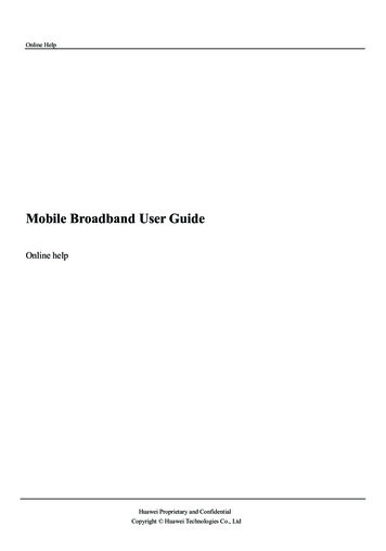
IntroductionWhile there have been great advances made in the speed and ease of implementation of Wi-Fi networks, thebasic nature of radio frequency (RF) is generally unchanged. Increasing the number of users who can access theWLAN in a small physical space remains a challenge. The steps and process for a successful high user densityWLAN design that can be proven, implemented, and maintained using Cisco’s Unified Wireless Networkarchitecture is detailed. It includes these general steps: Plan: Determine application and device requirements such as bandwidth, protocols, frequencies, servicelevel agreement (SLA), etc. Design: Determine density, cell sizing, antennas, coverage, site survey, etc. Implement: Install, test, tune, establish baseline, etc. Optimize: Monitor, report, adjust, review baseline for SLA. Operate: Cisco Wireless Control System (WCS) monitoring, troubleshooting tools, capacity monitoringand reporting tools, etc.The general concepts underlying high-density Wi-Fi design remain true for many environments. But it isimportant to note that the content and solutions presented here will not fit every WLAN design scenario. Rather,the intent of the guide is to explain the challenges in WLAN design for high-density client environments and tooffer successful strategies so that engineers and administrators understand them and are able to articulate theimpact design decisions will have.Target Environmental Characteristics for WLANsin Higher Education EnvironmentsHigh-density WLAN design refers to any environment where client devices will be positioned in densities greaterthan coverage expectations of a normal enterprise deployment, in this case a traditional, carpeted office. Forreference, a typical office environment has indoor propagation characteristics for signal attenuation. User densityis the critical factor in the design. Aggregate available bandwidth is delivered per radio cell, and the number ofusers and their connection characteristics (such as speed, duty cycle, radio type, band, signal, and SNR)occupying that cell determines the overall bandwidth available per user.A typical office environment, Figure 1, may have APs deployed for 2,500 to 5,000 square feet with a signal of-67 decibels in millowatts (dBm) coverage and a maximum of 20 to 30 users per cell. That is a density of oneuser every 120 square foot (sq. ft.) and yields a minimum signal of -67 dBm.Figure 1.Typical Office WLAN 2017 Cisco and/or its affiliates. All rights reserved. This document is Cisco Public Information.Page 5 of 41
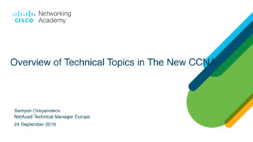
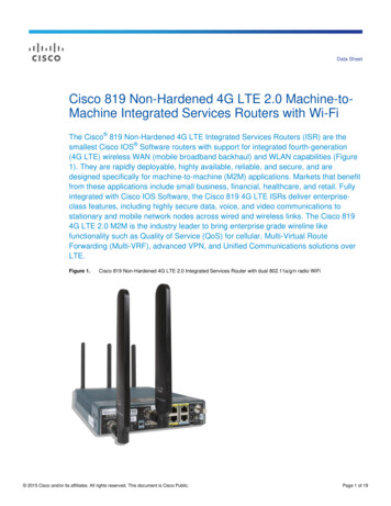
In planning and deploying such a WLAN, an AP is typically placed in an area expected to have a higher userdensity, such as in a conference room, while common areas are left with less coverage. In this way, preplanning for high-density areas is anticipated. Conference rooms are often placed in clusters, so it is best todesign for the maximum capacity of the area. For example, maximum occupancy for the three rooms is 32, souser density would be one user per 28 square feet, Figure 2.Figure 2.Calculating User DensityIn a high-density environment such as a lecture hall or auditorium, the densities of users in the occupied spaceincrease dramatically. User seating is typically clustered very close together to achieve high occupancy. Theoverall dimensions of the space are really only useful for getting an idea of the free space path loss of the APsignal. User densities are not evenly distributed over the entire space as aisle ways, stages, and podiumsrepresent a percentage of space which is relatively unoccupied. The RF dynamics of the AP are very differentfrom those experienced at the user level. The APs are exposed with an excellent view of the room and the userdevices will be packed closely together with attenuating bodies surrounding them.The single biggest sources of interference in the room are the client devices themselves. For each user sitting inthe auditorium who can rest their hand comfortably on the back of the seat in front of them, the distance isapproximately three feet, with an average seat width of 24 inches. This yields what is defined as a high-densityenvironment, with less than 1 square meter per device deployed, assuming one or more devices connected perseat. 2017 Cisco and/or its affiliates. All rights reserved. This document is Cisco Public Information.Page 6 of 41
Figure 3.Seating and InterferenceWhat is ultimately going to effect the client devices more than any other factor is the degradation of signal-tonoise ratio (SNR) through both co-channel and adjacent channel interference driven by co-located devices.Proper system engineering can minimize the impact by maximizing proper spatial reuse but it cannot beeliminated in highly dense environments entirely. Operating margins become more critical as space iscondensed and a bad radio or behavior in the mix can have a large impact within a cell. Client behavior underthese conditions will vary widely and trends based on environment and event type have also been reported.There is not much that can be done about the particular client mix or behavior. The design goal is to engineerthe network side as robustly as possible and to control and understand all variables.Within environments that qualify as high-density, there are also submodels built by use case. For example, in ahigh-density environment such as a public venue or stadium, capacity is planned based on what percentage ofusers are likely to be active on the network at any one time. In higher education there is a different model,where casual WLAN activity is one use case while activity when a professor is lecturing may increasedramatically, up to 100 percent.PlanningThe WLAN design process can begin in many ways but generally it begins with an expressed desire to provideconnections to a specific area where a number of users will participate in a focused activity. To evaluate what ispossible, it is first necessary to understand what is required as well as what is possible. There is generally aprimary application that is driving the need for connectivity. Understanding the throughput requirements for thisapplication and for other activities that will take place on the network will provide the designer with a per-userbandwidth goal. Multiplying this number by the number of expected connections yields the aggregatebandwidth that will be required.The required per connection bandwidth will be used to drive subsequent design decisions. 2017 Cisco and/or its affiliates. All rights reserved. This document is Cisco Public Information.Page 7 of 41
Design Point #1: Establish and Validate aPer-Connection Bandwidth RequirementHow much bandwidth does each user require on average? In Table 1, the nominal throughput requirementsfor several popular applications and use cases in a higher education setting are shown.Table 1.Bandwidth Requirements per ApplicationApplication by Use CaseNominal ThroughputWeb - Casual500 kilobits per second (Kbps)Web - Instructional1 Megabit per second (Mbps)Audio - Casual100 KbpsAudio - Instructional1 MbpsOn-demand or Streaming Video - Casual1 MbpsOn-demand or Streaming Video - Instructional2-4 MbpsPrinting1 MbpsFile Sharing - Casual1 MbpsFile Sharing - Instructional2-8 MbpsOnline Testing2-4 MbpsDevice Backups10-50 MbpsIn all cases, it is highly advisable to test the target application and validate its actual bandwidth requirements.Software designers are often required to pick just one average number to represent the application’srequirements when there are actually many modes and deployment decisions that can make up a moreaccurate number. It is also important to validate applications on a representative sample of the devices that areto be supported in the WLAN. Additionally, not all browsers and operating systems enjoy the same efficiencies,and an application that runs fine in 100 kilobits per second (Kbps) on a Windows laptop with Microsoft InternetExplorer or Firefox, may require more bandwidth when being viewed on a smart phone or tablet with anembedded browser and operating system.Once the required bandwidth throughput per connection and application is known, this number can be used todetermine the aggregate bandwidth required in the WLAN coverage area. To arrive at this number, multiply theminimum acceptable bandwidth by the number of connections expected in the WLAN coverage area. Thisyields the target bandwidth needed for the need series of steps.Design Point #2: Calculate the Aggregate ThroughputRequired for the Coverage AreaIf this design guide was for a wired rather than wireless network, calculating aggregate throughput requirementswould entail dividing the aggregate capacity by the channel bandwidth available. Then, the number of channelswould be established and these would be plugged into a switch. But in a WLAN, a channel’s speed is effectedby multiple factors including protocols, environmental conditions, and operating band of the adapter. Beforecalculating aggregate throughput, several things must be considered.In the aggregate throughput calculation, the connections instead of the seats were used as the basis forcalculation. The number of connections in a cell is what determines the total throughput that will be realized perconnection instead of the number of seats. Most users today carry both a primary computing device (such as asmartphone, tablet computer, or laptop) as well as a second device (such as a smartphone). Each connectionoperating in the high-density WLAN consumes air time and network resources and will therefore be part of theaggregate bandwidth calculation. An increase in numbers of device connections is one of the primary reasonsolder WLAN designs are reaching oversubscription today. 2017 Cisco and/or its affiliates. All rights reserved. This document is Cisco Public Information.Page 8 of 41
Wi-Fi is a shared medium. Much like an un-switched Ethernet segment, it operates as a half duplex connection.Only one station can use the channel at a time and both the uplink and downlink operate on the same channel.Each channel or cell used in a Wi-Fi deployment represents a potential unit of bandwidth much like an Ethernetconnection to a hub. In Ethernet, switching technology was developed to increase the efficiency of the mediumby limiting the broadcast and collision domains of a user to a physical port and creating point-to-pointconnections between ports on an as-needed basis, dramatically increasing the overall capacity.Users and applications also tend to be bursty (a measure of the unevenness or variations in the traffic flow) innature and often access layer networks are designed with a 20:1 oversubscription to account for thesevariances. Application and end user anticipated usage patterns must be determined and also accounted for.Some applications, such as streaming multicast video, will drive this oversubscription ratio down while othersmay drive this factor even higher to determine an acceptable SLA for each cell’s designed capacity.For 802.11 wireless networks or any radio network in general, air is the medium of propagation. While therehave been many advances in efficiency, it is not possible to logically limit the physical broadcast and collisiondomain of an RF signal or separate it’s spectrum footprint from other radios operating in the same spectrum. Forthat reason, Wi-Fi uses a band plan that breaks up the available spectrums into a group of non-overlappingchannels.A channel represents a cell. Using the analogy of Ethernet, a cell represents a single contiguous collisiondomain.How many users can access an AP comfortably? Hundreds. But the question should not be how many users cansuccessfully associate to an AP but how many users can be packed into a room and still obtain per-userbandwidth throughput that is acceptable.802.11 and Scalability: How Much BandwidthWill a Cell Provide?To scale 802.11 networks to reliably deliver consistent bandwidth to a large number of users in close proximity,it is important to examine certain WLAN fundamentals under reasonably ideal conditions. Once the rules areunderstood, the ways to manipulate them to maximum advantage will be presented.In real WLANs, the actual application throughput is what matters to the end user, and this differs from thesignaling speed. Data rates represent the rate at which data packets will be carried over the medium. Packetscontain a certain amount of overhead that is required to address and control the packets. The applicationthroughput is carried as payload data within that overhead. Table 2 shows average application throughput byprotocol under good RF conditions.Table 2.Average Application Throughput by ProtocolProtocolThroughput (Mbps)802.11b7.2802.11b/g mix13802.11g25802.11a25802.11n - HT20 one spatial stream (1ss) Modulation Coding Scheme 7 (MCS7)25802.11n - HT20 2ss Modulation Coding Scheme 15 (MCS15)70802.11n - HT40 2ss Modulation Coding Scheme 15 (MCS15)160 2017 Cisco and/or its affiliates. All rights reserved. This document is Cisco Public Information.Page 9 of 41
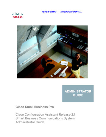
Are 802.11n Data Rates Dependable?Today, many clients are 802.11n ready and this can provide throughput and efficiency increases in a highdensity deployment. Most WLANs, however, will support a mix of client protocols. Evaluating the historic averageclient mix in a WLAN is possible by either looking at the WLAN controller graphical user interface (GUI) or atCisco Wireless Control System reports and using this historic mix of information for planning purposes. Unlessthe WLAN is very unique, most environments will likely be dealing with a diverse mix of clients and protocols forthe near future. Consider that other factors, such as the number of connections, can also be expected to varyover time and for these reasons it is often a best practice to build in some buffer to smooth the long termresults. The raw speed advantage of 802.11n high throughput (HT) rates is impressive and boosts the overallefficiency and capacity of the design by permitting more users or higher speeds to be realized on the samechannel. Figure 4 shows mixed client protocol capacities for a given cell.Figure 4.Mixed Wireless Client Protocol Performance in a Cell (802.11a/g/n Data Rates)The graph above shows throughput rates under varying mixes of HT20 modulation coding scheme-15(MCS15) 2SS data rates and legacy 802.11a/g (for the purpose of this discussion 802.11a and 802.11g arethe same protocol - different bands and are considered equal) data rates within a single isolated cell. With either all MCS15 or all 802.11a/g clients, the difference in throughput is 480percent. With a 50/50 mix, there is a 400 percent increase over legacy throughput. With a drop to just 25 percent of MCS15 clients, the increase is 300 percent. 2017 Cisco and/or its affiliates. All rights reserved. This document is Cisco Public Information.Page 10 of 41
In this example using 30 connections, the application throughput to the end user would be 833 Kbps with alllegacy connections or 3.9 Mbps with all 802.11n connections. A mix drives throughput down. Other variables,such as user density or environmental noise, can and likely will change over time and will effect the throughputas well.Using legacy data rates as a nominal value, Table 3 shows the relationship between cell bandwidth and perconnection bandwidth.Table 3.Data Throughput and User Connections per Wireless ProtocolProtocolData Rate (Mbps)Aggregate Throughput(Mbps)Example User CountAverage Per UserThroughput802.11b117.210720 Kbps802.11b117.220360 Kbps802.11b117.230240 Kbps802.11b/g5413101.3 Mbps802.11b/g541320650 Kbps802.11b/g541330430 Kbps802.11a5425102.5 Mbps802.11a5425201.25 Mbps802.11a542530833 Kbps802.11n MCS77235103.5 Mbps802.11n MCS77235201.75 Mbps802.11n MCS77235301.16 MbpsA mixed cell containing both 802.11b and 802.11g traffic results in a throughput rate that is less than doublethat of 802.11b alone and roughly half of 802.11g alone. A similar effect was seen when 802.11n and legacy802.11a/g rates were compared. Until the inclusion of 802.11n, all advances in Wi-Fi technology have comethrough incremental increases in encoding technology. 802.11n changed the encoding and streamlined thelogistics of bonding 20 MHz channels and increasing the available channel bandwidth. In implementing newtechnology, it is also necessary to provide a mechanism that allows the old and the new protocols to coexist. It isthis mechanism that reduces the overall efficiency of the channel due to additional overhead. An 802.11bmodem was not designed to speak 802.11g. In order to avoid collisions, the 802.11b radios must be informedthat the channel is needed by 802.11g for a period of time.In a high-density environment, every available efficiency must be taken advantage of to achieve the desired goalof maximum throughput and access. Figure 5 shows the relationship of per frame air time (channel utilization),frame sizes, and data rates. 2017 Cisco and/or its affiliates. All rights reserved. This document is Cisco Public Information.Page 11 of 41
Figure 5.Per Frame Channel Utilization, Frame Sizes, and Data Rates in a WLANThe time scale above is in microseconds (µs). At the top end of the chart, a 2048 byte packet is transmitted at1 Mbps, taking almost .02 seconds of airtime. Only one packet can be in the air at a time, and the faster thatpacket gets through, the better use made of the time available. Looking at this from a different perspective,reaching the bandwidth goals while supporting 802.11b and 802.11g will require more radios and cells and moreadvanced isolation techniques to implement them successfully.Theoretically, if three radios could be put on the same pole serving all three non-overlapping channels in thesame cell, a cell could be created that holds three times the bandwidth in 2.4 GHz and as much as 20 times thatin 5 GHz, Figure 6.Figure 6.Total Capacity of Three 2.4 GHz Radios on One CellIn 5 GHz, there is more spectrum and the resulting bandwidth for a theoretical single cell increasesdramatically, Figure 7. 2017 Cisco and/or its affiliates. All rights reserved. This document is Cisco Public Information.Page 12 of 41
Figure 7.21 Channels on One 5 GHz Cell, and Resulting CapacityWith today’s radio designs, the radio could almost be placed on top of each another, but that would not servethe high-density design well. It would result in the same coverage area of a single cell and likely would notcover the required area, even in a relatively small lecture hall.Data rates are a function of the received signal strength and the signal to noise ratio (SNR) at the receiver. It isnot practical or efficient to lock a radio down to a particular data rate since the radio makes efficiency decisionsbased on available link conditions. Not every client will respond the same in an otherwise static environment.Variables such as receiver sensitivity, antenna configuration, driver version, and even position within the cell inrelation to attenuating or reflecting objects will have a variable effect on the client. An environment that isconducive to good radio efficiency can be helped by appropriate design. The higher the average received signalstrength and the better the SNR, the faster the data rate will be.Cisco’s ClientLink technology can increase the signal selectively for legacy 802.11 a/g Orthogonal FrequencyDivision Multiplexing (OFDM) clients. Since legacy clients do not support the efficiency gains realized with802.11n clients, they represent the least efficient clients in our design. Using ClientLink in a high-density userdesign allows the AP to improve SNR from 3-6 dB on a packet-by-packet basis for a client that is indicating theneed to rate shift. This has the overall effect of increasing the range and rate equation for the network andencourages legacy clients to maintain higher data rates under adverse conditions. This is an excellent additionto a high-density design. The document Cisco ClientLink: Optimized Device Performance for 802.11n providesa full discussion of the Cisco ClientLink technology.In a high-density deployment, channels will be aggregated to increase the total bandwidth. This means movingthe APs ever closer together in the design space. A key success factor is Co-Channel Interference (CCI). CCIeffects capacity of the cell by reducing the available bandwidth.What Is Co-Channel Interference and Why Is ItImportant in High-Density WLANs?CCI is a critical concept to understand when it comes to understanding the behavior and performance of802.11 WLANs. It is a phenomenon where transmissions from one 802.11 device bleed into the receive rangeof other 802.11 devices on the same channel, causing interference and reducing the available spectrum andresulting performance. CCI can cause channel access delays as well as collisions in transmissions that corruptframes in transit. Figure 8 illustrates how APs on the same channel interfere with each
The general concepts underlying high-density Wi-Fi design remain true for many environments. But it is important to note that the content and solutions presented here will not fit every WLAN design scenario. Rather, the intent of the guide is to explain the challenges in WLAN design for high-density client environments and to