Transcription
GEMeasurement & ControlRod Load Calculations andDefinitions for ReciprocatingCompressor MonitoringGER-4490B (01/15)Author:Brian Howard, P.E.Sr. TechnologistReciprocating Compressor Condition MonitoringGE Measurement & Control
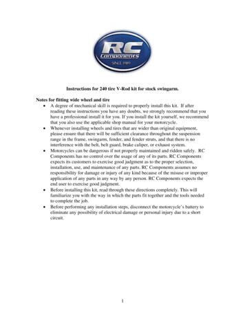
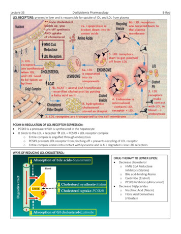
IntroductionCalculation MethodologyThe term “rod load” has been used for decades to describe theFigure 1 shows the rod load curves and data generated by 3500/S1.maximum forces a reciprocating compressor assembly canInertial Forcewithstand. The term has some ambiguity, but recent papers haveclarified some of the key definitions and terms1.The red line in Figure 1 represents the forces due to inertiaforces. The inertia mass for nearly all reciprocating compressorWith the improved understanding beginning to permeate industry,condition monitoring installations includes the crossheadcustomers have begun to ask questions about how GE’s Bentlyassembly, crosshead nut, piston rod, and piston assembly.Nevada* 3500 Series Monitoring Systems and System 1* ConditionThis collection of mass for inertia is consistent with the definitionMonitoring Software (referred to as 3500/S1 hereafter) calculateprovided in API-618 5th Edition (Data Sheets, Page 7, line 31)2.these values. The purpose of this note is to answer those questions.3500/S1 does allow the user to exclude the crosshead massThe terminology and context for this application note are AmericanPetroleum Institute (API) Standard 618, 4th edition and 5th edition2.Previous editions of API 618 used other descriptions and definitionsfor rating values of reciprocating compressors. For ease offrom the inertia force calculations (see Figure 3); however, theconfiguration is rarely encountered in the field, is not consistentwith API-618 4th or 5th edition terminology, and is outside thescope of this application note.reference, the terms and definitions used herein appear at the endof this application note.SynchFrom 06MAY2002 21:02:42 To 06MAY2002 21:02:42HistoricalMACHINE SPEED: 276 rpmHistorical-55526.8 lbf (-246996 N)0 00 --COMPRESSION FORCE TENSION-- 44k N/div --COMPRESSION FORCE TENSION-- 10k lbf/divGas LoadCrank AngleMake-Up CompressorInertial LoadCrank AngleMake-Up CompressorCombined ForceCrank AngleMake-up CompressorTDC30020 Degrees/divCrank AngleFigure 1. Rod load curves generated by 3500/S1GE Measurement & Control GER-4490B (01/15)1
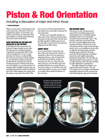
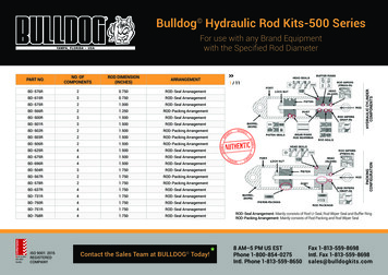
Gas ForceThe gas pressures in the chamber act not only on the piston, butThe blue line in Figure 1 represents the gas forces acting on thealso on the heads of each cylinder. The combined gas force on thecompressor’s static components and running gear. This force is thecrank and head end heads has the same absolute value as the gasgas load referenced in API-618 (paragraph 6.6.2)2. To obtain thisload calculated above, but acts in the opposite direction (i.e., hasforce, the indicated cylinder pressure on the head end is multipliedopposite sign).by the head end area of the piston. This is shown in green inFigure 2 for a typical double-acting cylinder. The resultant forceis then subtracted from the indicated crank end cylinder pressuretimes the crank end piston area (shown in brown in Figure 2). Thissummation represents the net force1 acting on the piston rod andcan be written as:Combined Rod LoadFinally, the green line in Figure 1 represents the combined rodload, or crosshead pin load. This force is the combined rod loadreferenced in API-618 (paragraph 6.6.1)2. The gas load is added tothe inertia force at each point of measurement to obtain this force.Since, as noted in the previous section, the gas load is computed720 times for each crankshaft revolution, 3500/S1 also performsthe combined rod load calculation 720 times for each crankshaftThe cylinder pressure varies continuously throughout therevolution. For each of these 720 points of measurement duringrevolution of the crankshaft so the calculations must be performedthe crankshaft revolution, the calculation can be written as:multiple times throughout the revolution to obtain a curve. Foreach 360 degrees of crankshaft rotation, 3500/S1 collects 720indicated cylinder pressure data points simultaneously for both thehead and crank end. The gas load calculation is thus performed720 times for each revolution.When the mass used in the inertia force calculation includes thecrosshead, the smallest distance between the points of zero force(shown by black dots at approximately 35 and 200 of crank anglein Figure 1) represents the degrees of rod reversal referenced inAPI-618 (paragraph 6.6.4)2.Had 3500/S1 been configured to calculate rod load at the pistonrod, the inertia forces would no longer include the crosshead mass.Figure 2. Piston areas used for gas rod load calculationThe combination of this inertia force and gas force results in theforces that act on the piston rod, next to the crosshead. Note thatthis force no longer reflects those acting on the crosshead pin, andtherefore cannot be used to calculate rod reversal./77M Cylinder Pressure Mon - HP CYL1 CHP510-XM1Throw:ACylinder:1Chamber:Crank EndRack Type:StandardSlot:3Channel:2 (Active)EnableTransducer PropertiesFull-scale RangeCrank End / Inner End HeadDischarge Pressure0-100 psigClamp Value0Suction Pressure0-100 psig0Maximum Pressure0-100 psig0Minimum Pressure0-100 psig0Compression Ratio0-100 psig1Rod LoadAt Crosshead PinAt Piston RodPeak Rod CompressionPeak Rod TensionHead End / Outer End HeadDegrees of Rod ReversalAPI618 ConventionNon-API618 ConventionOKFigure 3. Reciprocating compressor terminology2Set Defaults0-10000 lbf00-10000 lbf00-180 deg0CancelProperties.BarriersNoneAlarm ModeAlertLatchingNonlatchingDelayAlert 301 - 60 sDangerLatchingNonlatchingCP ModFigure 4. 3500/77M configuration screenPrintDanger301 - 60 sHelp3500
ConclusionRod load curves and peak rod load / reversal values provideimportant insight into the health of a reciprocating compressor.Understanding how 3500/S1 calculates these values and how theyrelate to OEM and API-618 definitions enables end users to bettermanage their reciprocating compressors.Bibliography Gas Load: The force resulting from the internal pressure ineach chamber acting on the associated piston and cylinderhead surfaces.This is the curve labeled “Gas Force” in System 1 software plots.As it depends only on the pressure and cylinder geometry, itremains the same whether the force calculation is done at thecrosshead pin or piston rod. The term appeared in both the 4thand 5th editions of API-618 with the same definition; however,4th edition required that it be calculated every 10 degrees andthe 5th edition required that it be calculated every 5 degrees.1. Atkins, K.E.; Hinchliff, M.; McCain, B., “A Discussion of the VariousLoads Used to Rate Reciprocating Compressors.” Proceedings ofthe Gas Machinery Conference, 2005.2. API Standard 618, Fifth Edition (2007), “Reciprocating Maximum Allowable Continuous Combined Rod Load(MACCRL): A value determined by the Original equipmentManufacturer (OEM) based on design limits of the variouscomponents in the compressor frame and the running gearCompressors for Petroleum, Chemical, and Gas Industry(bearings, crankshaft, connecting rod, crosshead assembly,Services,” American Petroleum Institute, Washington, D.C.piston rod, piston assembly).Terms and DefinitionsThe following definitions draw extensively from reference (1). Thereader is encouraged to consult this reference for a completediscussion of these terms and others, as well as a valuablehistorical perspective. Combined Rod Load: The sum of actual gas load (includingvalve and passage losses) plus inertia loads at the crosshead pin,in the direction of the piston rod.This is the force curve labeled “Combined Force” in System 1software’s rod load plots when the inertia force includes themass of the crosshead assembly. This force varies continuouslythroughout the revolution. The term appeared in both the4th and 5th edition of API-618 with the same definition;however the 4th edition required that it be calculated everyWith minor exceptions (see 6.6.5 of API-618, 5th edition),no single value of combined rod load can exceed themanufacturer’s ratings for maximum allowable continuouscombined rod load (see paragraph 3.19 of API-618 5th editionfor a formal definition). OEMs may have individual limits forcompressive rod load, tension rod load, and compressiveplus tension. Maximum Allowable Continuous Gas Load (MACGL): A valuedetermined by the OEM based on the design limits of the staticcomponents (frame, distance piece, cylinder and bolting).With minor exceptions (see 6.6.5 of API-618, 5th edition), nosingle value in the gas load curve can exceed the manufacture’sratings for maximum allowable continuous gas load. Reference3.20 of API-618 5th edition for a formal definition. Rod Reversal: The shortest distance, measured in degrees of10 degrees and the 5th edition required that it be calculatedcrank revolution, between each change in sign of force in theevery 5 degrees. Reference 3.7 of API-618 5th edition for acombined rod-loading curve.formal definition.Reference paragraph 3.49 of API-618 5th edition for a formal Crosshead Pin Load: Same definition as “combined rod load.”Note this term is not defined within API-618, but is a commonlyencountered industry term used to clarify the component atdefinition; however, note that the API 618 definition is notentirely accurate as it references “piston rod loading” instead of“combined rod loading.”which the combined rod load calculations are being done.GE Measurement & Control GER-4490B (01/15)3
Notes4
GE Measurement & Control1631 Bently Parkway SouthMinden, NV 89423 1 775.782.3611www.ge-mcs.com/bently* Bently Nevada and System 1 are trademarks of the General Electric Company. 2015, General Electric Company. All rights reserved.GER-4490B (01/15)
important insight into the health of a reciprocating compressor. Understanding how 3500/S1 calculates these values and how they relate to OEM and API-618 definitions enables end users to better manage their reciprocating compressors. Bibliography 1. Atkins, K.E.; Hinchliff, M.; McCain, B., “A