Transcription
C H A P T E R3Troubleshooting Hardware and BootingProblemsThis chapter provides procedures for troubleshooting hardware and booting problems. Although itprovides specific procedures for some Cisco products, always refer to your hardware installation andmaintenance publication for more detailed information about your specific platform, includingdescriptions of specific LEDs, configuration information, and additional troubleshooting information.This chapter begins with the following sections on hardware problems: Cisco 7500 Series Startup—Describes hardware and boot process troubleshooting for Cisco 7500series routers Cisco 7000 Series Startup—Describes hardware and boot process troubleshooting for Cisco 7000series routers Cisco 4000 Series Startup—Describes hardware and boot process troubleshooting for Cisco 4000series routers Cisco 2500 Series Startup—Describes hardware and boot process troubleshooting for Cisco 2500series routers Catalyst 5000 Series Startup—Describes hardware and boot process troubleshooting for Catalyst5000 series LAN switches Catalyst 2900 Series Startup—Describes hardware and boot process troubleshooting for Catalyst2900 series LAN switches Testing and Verifying Replacement Parts—Provides suggested actions when swapping routerhardware Catalyst 6000 Series Startup—Describes hardware and boot process troubleshooting for Catalyst6000 series LAN switches Cisco 2600 Series Startup—Describes hardware and boot process troubleshooting for Cisco 2600series routers Cisco 3600 Series Startup—Describes hardware and boot process troubleshooting for Cisco 3600series routers Catalyst 4000 Series Startup—Describes hardware and boot process troubleshooting for Catalyst4000 series LAN switchesThe remaining sections describe symptoms, problems, and solutions for Flash boot, network boot usingTFTP, ROM boot, and other bootup problems: Booting: Router Fails to Boot from Flash Memory Booting: Vector Error Occurs When Booting from Flash MemoryInternetworking Troubleshooting Handbook, Second Edition1-58705-005-63-1
Chapter 3Troubleshooting Hardware and Booting ProblemsBooting the Router Booting: Router Partially Boots from Flash and Displays Boot Prompt Booting: Router Cannot Network boot from TFTP Server Booting: Router Cannot Network boot from Another Router Booting: Timeouts and Out-of-Order Packets Prevent Network booting Booting: Invalid Routes Prevent Network booting Booting: Client ARP Requests Timeout During Network boot Booting: Undefined Load Module Error When Network booting Booting: Router Hangs After ROM Monitor Initializes Booting: Router Is Stuck in ROM Monitor Mode Booting: Scrambled Output When Booting from ROM Booting: Local Timeouts Occur When Booting from ROM Booting: Unresponsive Terminal Connection to Unconfigured Access ServerBooting the RouterCisco routers can initialize the system (boot) in four ways: Network boot—Routers can boot from a server using the Trivial File Transfer Protocol (TFTP), theDEC Maintenance Operation Protocol (MOP), or the Remote Copy Protocol (RCP) across any ofthe supported media types (such as Ethernet, Token Ring, Fiber Distributed Data Interface [FDDI],High-Speed Serial Interface [HSSI], and serial lines). Flash memory—Routers can boot from Flash memory, a nonvolatile storage medium that can beelectrically erased and reprogrammed. ROM—Routers can boot a system from built-in read-only memory (ROM). PC Flash memory card—Routers can boot from a removable Flash memory card.This section provides general information about router booting.Network Booting TipsDuring network booting sessions, routers behave like hosts. They route via proxy Address ResolutionProtocol (ARP), Serial Line Address Resolution Protocol (SLARP) information, Internet ControlMessage Protocol (ICMP) redirects, or a default gateway. When network booting, routers ignoredynamic routing information, static IP routes, and bridging information. As a result, intermediate routersare responsible for handling ARP and User Datagram Protocol (UDP) requests correctly. For serial andHSSI media, ARP is not used.Before network booting from a server, you should ping the server from the ROM software. If you cannotping the server, follow the procedures described in the section “Booting: Router Cannot Network bootfrom TFTP Server,” later in this chapter. If you still cannot ping the server, there is probably a serverconfiguration or hardware problem. Refer to your TFTP server documentation, or contact your technicalsupport representative for assistance.Internetworking Troubleshooting Handbook, Second Edition3-21-58705-005-6
Chapter 3Troubleshooting Hardware and Booting ProblemsBooting the RouterFault-Tolerant Boot StrategiesAlthough network booting is useful, network or server failures can make network booting impossible.After you have installed and configured the router’s Flash memory, configure the boot sequence for therouter to reduce the impact of a server or network failure. The following order is recommended:1.Boot an image from Flash memory.2.Boot an image using a network boot.3.Boot from a ROM image.The following is an example of how to configure a router with a fault-tolerant boot sequence.goriot# configure terminalEnter configuration commands, one per line. End with CNTL/Z.goriot(config)# boot system flash gsxxgoriot(config)# boot system gsxx 131.108.1.101goriot(config)# boot system romgoriot(config)# Zgoriot#%SYS-5-CONFIG I: Configured from console by consolegoriot# copy running-config startup-config[ok]goriot#Using this strategy, a router has three sources from which to boot: Flash memory, network boot, andROM. Providing alternative sources can help to mitigate any failure of the TFTP server or the network.NoteThe configuration register must be set to allow ROM image booting after failed networkbooting attempts. For more information, refer to the hardware configuration manual foryour platform.Timeouts and Out-of-Order PacketsWhen network booting, a client might need to retransmit requests before receiving a response to an ARPrequest. These retransmissions can result in timeouts and out-of-order packets.Timeouts (shown as periods in a network booting display) and out-of-order packets (shown as uppercaseO’s) do not necessarily prevent a successful network boot. It is acceptable to have either or both timeoutsor out-of-order packets occur during the network boot process.The following examples show console output from network booting sessions that were successful eventhough timeouts and out-of-order packets occurred (exclamation points represent successfully receivedpackets):Booting gs3-bfx from 131.108.1.123: !.!!!!!!!!!!!!!!!!!!!!!!Booting gs3-bfx from 131.108.1.123: !O.O!!!!!!!!!!!!!!!!!!!!!!If a network boot generates excessive out-of-order packets and timeouts, problems might result. Theseproblems are discussed later in this chapter, in the section “Booting: Timeouts and Out-of-Order PacketsPrevent Network booting.”Internetworking Troubleshooting Handbook, Second Edition1-58705-005-63-3
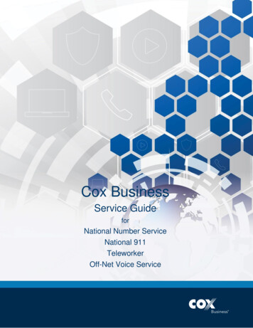
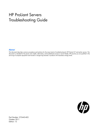
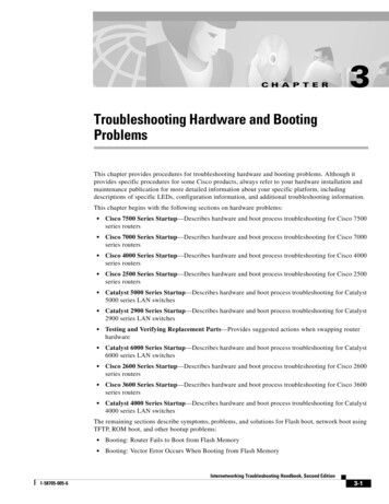
Chapter 3Troubleshooting Hardware and Booting ProblemsTroubleshooting HardwareInformation for Technical SupportIf you cannot resolve your booting problem using the procedures outlined in this chapter, collect thefollowing information for your technical support representative: ROM images. (Use the show version exec command.) Programmable ROM labels. (This information is printed on the physical chip, and an example isshown in Figure 3-1.)Figure 3-1An Example of a Boot ROM Label—Boot ROM Version 11.1(2)U30 v11 1(2)RS P2-ROMMONO17-2111-04Cisco Systems NVRAM configurations for client and adjacent routers. Debugging output from adjacent routers using the following privileged exec commands:– debug ip packet– debug arp– debug ip udp– debug tftpFor more information about these debug commands, refer to the Debug Command Reference.Troubleshooting HardwareThis section discusses procedures for connectivity problems related to booting. It describes specificbooting symptoms, the problems that are likely to cause each symptom, and the solutions to thoseproblems.Cisco 7500 Series StartupWhen you start up a Cisco 7500 series router, the following should occur: The AC (or DC) OK LED should go on immediately and should remain on as long as the system isreceiving power. The blower should be operating. The Route Switch Processor (RSP) and front-panel Normal LEDs should go on (to indicate normalsystem operation) and should remain on during system operation; the CPU Halt LED should remainoff. The Enabled LED on each interface processor should go on (to indicate that the RSP has completedinitialization of the interface processor).Internetworking Troubleshooting Handbook, Second Edition3-41-58705-005-6
Chapter 3Troubleshooting Hardware and Booting ProblemsTroubleshooting HardwareWhen the 7500 series system has initialized successfully, the system banner should be displayed on theconsole screen. If it is not displayed, make sure that the console terminal is properly connected to theRSP console port and that the terminal is set correctly. The system banner should look similar to thefollowing:System Bootstrap, Version 4.6(5), SOFTWARECopyright (c) 1986-1995 by cisco SystemsRSP2 processor with 16384 Kbytes of memory### [.] ###F3: 2012356 47852 194864 at 0x1000Restricted Rights LegendUse, duplication, or disclosure by the Government issubject to restrictions as set forth in subparagraph(c) of the Commercial Computer Software - RestrictedRights clause at FAR sec. 52.227-19 and subparagraph(c) (1) (ii) of the Rights in Technical Data and ComputerSoftware clause at DFARS sec. 252.227-7013.cisco Systems, Inc.170 Tasman DriveSan Jose, CA 95134GS Software (RSP-K), Version 10.3(571) [fc3], RELEASE SOFTWARECopyright (c) 1986-1995 by cisco Systems, Inc.[.]Press RETURN to get started!If a problem occurs, try to isolate the problem to a specific subsystem. The Cisco 7500 series routershave the following subsystems: Power subsystem—Includes power supplies, external power cable, and backplane Cooling subsystem—Depending on your system, includes the following:– Cisco 7505—Fan tray, fan tray spare with six individual fans, and fan control board– Cisco 7507—Chassis blower– Cisco 7513—Blower module, including blower, blower-speed control board, front-panel LEDs,and the module itself Processor subsystem—Depending on your system, includes all interface processors and either theRSP1 or the RSP2Internetworking Troubleshooting Handbook, Second Edition1-58705-005-63-5
Chapter 3Troubleshooting Hardware and Booting ProblemsTroubleshooting HardwareTable 3-1 outlines the areas where Cisco 7500 series startup problems may occur and describes solutionsto those problems.Internetworking Troubleshooting Handbook, Second Edition3-61-58705-005-6
Chapter 3Troubleshooting Hardware and Booting ProblemsTroubleshooting HardwareTable 3-1Hardware: Cisco 7500 Series Startup Problems and SolutionsPossible Problem AreaPower subsystemSolution1.Check to see whether the blower is operating and thatLEDs on the processor modules are on. If the blowerand LEDs are on but the Power Supply LED is off,there is probably a faulty Power Supply LED.2.Make sure that the power switch is set correctly to theon position.3.Make sure that the power source, power cable, andpower supply are functioning correctly. Swap parts tosee whether one of the components is faulty.4.Ensure that the blower module is seated properly. Makesure that the blower control board edge connector isinserted fully in the backplane socket.Internetworking Troubleshooting Handbook, Second Edition1-58705-005-63-7
Chapter 3Troubleshooting Hardware and Booting ProblemsTroubleshooting HardwareTable 3-1Hardware: Cisco 7500 Series Startup Problems and Solutions (continued)Possible Problem AreaCooling subsystemSolution1.Check to see whether the blower is operating when youstart up the system. If the blower is not operating, theremight be a problem with the blower or the 24 V DCpower: If the Output Fail LED is on, there might be a problemwith the 24V DC supply to the blower or fan tray ateither the power supply or the blower control board. If the blower is not operating and the Output Fail LEDis off, ensure that the blower module is seated properly.Ensure that the blower control board edge connector isinserted fully in the backplane socket.2.If the system and blower start up but shut down afterabout 2 minutes, one or more fans might have failed ormight be operating out of tolerance. You will probablysee an error message similar to the following:%ENVM-2-FAN: Fan has failed, shutdown in 2minutesIf the blower or the blower control board fails, you mustreplace the blower module.3.If you see the following message at startup, the systemhas detected an overtemperature condition orout-of-tolerance power inside the chassis:Queued messages:%ENVM-1-SHUTDOWN: Environmental Monitorinitiated shutdownIf an environmental shutdown results from anout-of-tolerance power condition, the Output Fail LEDgoes on before the system shuts down.This shutdown message might also indicate a faultycomponent or temperature sensor. Before the system shutsdown, use the show environment or show environmenttable commands to display the internal chassisenvironment.4.Ensure that heated exhaust air from other equipment isnot entering the inlet vents and that there is sufficientclearance around the chassis to allow cooling air toflow.continuesInternetworking Troubleshooting Handbook, Second Edition3-81-58705-005-6
Chapter 3Troubleshooting Hardware and Booting ProblemsTroubleshooting HardwareTable 3-1Hardware: Cisco 7500 Series Startup Problems and Solutions (continued)Possible Problem AreaProcessor subsystemSolution1.Check the RSP1 LEDs. If no LEDs come on, ensurethat the power supplies and blower are functioningproperly.2.Check the seating of the RSP. If the RSP is not seatedproperly, it will hang the system.3.If the RSP CPU Halt LED is on, the system hasdetected a processor hardware failure. Contact atechnical support representative for instructions.4.Check to see whether the RSP Normal LED is on,indicating that the system software has initializedsuccessfully and that the system is operational.5.Check the Enabled LED on each interface processor.This LED should go on when the RSP has initializedthe interface processor.6.If the Enabled LED on an individual interfaceprocessor is off, the interface processor might havepulled away from the backplane. If the interfaceprocessors are not seated properly, they will hang thesystem.1. RSP Route Switch ProcessorCisco 7000 Series StartupWhen you start up a Cisco 7000 series router, the following should occur: The DC OK LED should go on and should remain on as long as the system is receiving source power. The fans should be operating. The Route Processor (RP) Normal LED should go on and stay on to indicate normal systemoperation; the Halt CPU LED should remain off. The Enabled LED on the Switch Processor (SP) or Silicon Switch Processor (SSP) and eachinterface processor should go on when the RP has completed initialization of the interface processoror SP (or SSP) for operation.Internetworking Troubleshooting Handbook, Second Edition1-58705-005-63-9
Chapter 3Troubleshooting Hardware and Booting ProblemsTroubleshooting HardwareWhen the system has initialized successfully, the system banner should be displayed on the consolescreen. If it is not displayed, make sure that the console terminal is properly connected to the RP consoleport and that the terminal is set correctly. The system banner should look similar to the following:System Bootstrap, Version 4.6(5), SOFTWARECopyright (c) 1986-1995 by cisco SystemsRP1 processor with 16384 Kbytes of memory### [.] ###F3: 2012356 47852 194864 at 0x1000Restricted Rights LegendUse, duplication, or disclosure by the Government issubject to restrictions as set forth in subparagraph(c) of the Commercial Computer Software - RestrictedRights clause at FAR sec. 52.227-19 and subparagraph(c) (1) (ii) of the Rights in Technical Data and ComputerSoftware clause at DFARS sec. 252.227-7013.cisco Systems, Inc.170 West Tasman DriveSan Jose, California 95134-1706GS Software (GS7), Version 10.3(1) [fc3], RELEASE SOFTWARECopyright (c) 1986-1995 by cisco Systems, Inc.RP1 (68040) processor with 16384K bytes of memory.[.]Press RETURN to get started!If problems occur, try to isolate the problem to a specific subsystem. The Cisco 7000 series routers havethe following subsystems: Power subsystem—Includes power supplies, fans, external power cable, and internal power harnessthat connects to the backplane Cooling subsystem—Depending on your system, includes the following:– Cisco 7000—Chassis blower– Cisco 7010—Fan tray assembly, including six individual fans, the fan control board, and thetray itself Processor subsystem—Includes the RP, SP (or SSP), and all interface processorsInternetworking Troubleshooting Handbook, Second Edition3-101-58705-005-6
Chapter 3Troubleshooting Hardware and Booting ProblemsTroubleshooting HardwareTable 3-2 outlines the areas where Cisco 7000 series startup problems may occur and describes solutionsto those problems.Table 3-2Hardware: Cisco 7000 Series Startup Problems and SolutionsPossible Problem AreaPower subsystemCooling subsystemSolution1.Check to see whether the DC OK LED is on.2.If the LED is not on but the fans are operating andLEDs on the processor modules are on, the PowerSupply LED might be faulty.3.If the LED is not on and there is no other activity, makesure that the power switch is fully in the on position.4.Make sure that the power source, power cable, andpower supply are functioning correctly. Swap parts tosee whether one of the components is faulty.5.Ensure that the fan tray is seated properly. Make surethat the fan control board edge connector is insertedfully in the backplane socket.1.Check to see whether the fans are operating.2.If the fans are not operating and the DC OK LED is off,there might be a problem with the 24V DC power.3.Ensure that the fan tray is seated properly. Make surethat the fan control board edge connector is insertedfully in the backplane socket.4.If the system and the fans start up but shut down afterabout 2 minutes, one or more fans has failed or isoperating out of tolerance. You will see an errormessage similar to the following:%ENVM-2-FAN: Fan array has failed, shutdown in2 minutesIf one or more fans or the fan control board fails, you mustreplace the fan tray.5.If you see the following error message, the system hasdetected an overtemperature condition orout-of-tolerance power inside the chassis:Queued messages:%ENVM-1-SHUTDOWN: Environmental Monitorinitiated shutdownIf an environmental shutdown results from anout-of-tolerance power condition, the DC OK LED will gooff before the system shuts down.Internetworking Troubleshooting Handbook, Second Edition1-58705-005-63-11
Chapter 3Troubleshooting Hardware and Booting ProblemsTroubleshooting HardwareTable 3-2Hardware: Cisco 7000 Series Startup Problems and Solutions (continued)Possible Problem AreaSolutionCooling subsystem(continued)This shutdown message could also indicate a faultycomponent or temperature sensor. Use the showenvironment or show environment table command todisplay the internal chassis environment.Processor subsystem6.Make sure that heated exhaust air from otherequipment is not entering the inlet vents, and that thereis sufficient clearance around the chassis to allowcooling air to flow.1.Check to see whether the RP1 LEDs come on whensystem power is turned on.2.If none of the RP LEDs come on, make sure that boththe fan and the power supply are functioning properly.3.If the power supply and fans appear operational butnone of the RP LEDs are on, an improperly connectedRP, SP 2 (or SSP3), or interface processor might havehung the bus.4.If the SP (or SSP) Enabled LED is off but any of the RPLEDs are on, make sure that the SP (or SSP) is seatedin its slot properly.5.Check to see whether the Boot Error LED is on. If theLED is on, the system software is incapable of startingup. If you have a spare RP with the system softwareROMs installed, replace the installed RP with the spareto see whether the system will boot.6.Check to see whether the RP CPU Halt LED is on. If itis, the system has detected a processor hardwarefailure. Contact a technical support representative formore information.7.Check to see whether all interface processor EnabledLEDs are on.8.If the Enabled LED on an individual interfaceprocessor is off, make sure that the interface processorhas not pulled away from the backplane.1. RP Route Processor2. SP Switch Processor3. SSP Silicon Switch ProcessorCisco 4000 Series StartupWhen you start up a Cisco 4000 series router, the following should occur: The System OK LED should come on and stay on as long as power is supplied. The fans should be operating.Internetworking Troubleshooting Handbook, Second Edition3-121-58705-005-6
Chapter 3Troubleshooting Hardware and Booting ProblemsTroubleshooting HardwareWhen the system has initialized successfully, the system banner should be displayed on the consolescreen. The system banner should look similar to the following:System Bootstrap, Version 4.14(9), SOFTWARECopyright (c) 1986-1994 by cisco Systems4000 processor with 16384 Kbytes of main memoryLoading xx-j-mz.112-0.15 at 0x4A790, size 3496424 bytes [OK]F3: 8988 3487404 165008 at 0x12000Self decompressing the image : ###[.]#### [OK]Restricted Rights LegendUse, duplication, or disclosure by the Government issubject to restrictions as set forth in subparagraph(c) of the Commercial Computer Software - RestrictedRights clause at FAR sec. 52.227-19 and subparagraph(c) (1) (ii) of the Rights in Technical Data and ComputerSoftware clause at DFARS sec. 252.227-7013.cisco Systems, Inc.170 West Tasman DriveSan Jose, California 95134-1706Cisco Internetwork Operating System SoftwareIOS (tm) 4000 Software (XX-J-M), Version 11.2(0.15), BETA TEST SOFTWARECopyright (c) 1986-1996 by cisco Systems, Inc.Compiled Wed 03-Jul-96 01:21 by susinghImage text-base: 0x00012000, data-base: 0x006F6494cisco 4000 (68030) processor (revision 0xA0) with 16384K/4096K bytes of memory.Processor board ID 5007155G.703/E1 software, Version 1.0.Bridging software.SuperLAT software copyright 1990 by Meridian Technology Corp).X.25 software, Version 2.0, NET2, BFE and GOSIP compliant.TN3270 Emulation software (copyright 1994 by TGV Inc).Basic Rate ISDN software, Version 1.0.2 Ethernet/IEEE 802.3 interfaces.4 Serial network interfaces.8 ISDN Basic Rate interfaces.128K bytes of non-volatile configuration memory.4096K bytes of processor board System flash (Read/Write)Press RETURN to get started!If problems occur, try to isolate the problem to a specific subsystem. The Cisco 4000 series routers havethe following subsystems: Power subsystem—This subsystem includes the power supply and the wiring. Cooling subsystem—This subsystem includes the blower assembly, which should come on whenpower is applied. Network processor modules (NPMs)—This subsystem includes all NPMs installed in the routerchassis. System cables—This subsystem includes all the external cables that connect the router to thenetwork.Internetworking Troubleshooting Handbook, Second Edition1-58705-005-63-13
Chapter 3Troubleshooting Hardware and Booting ProblemsTroubleshooting HardwareTable 3-3 outlines the areas where Cisco 4000 series startup problems may occur and describes solutionsto those problems.Table 3-3Hardware: Cisco 4000 Series Startup Problems and SolutionsPossible Problem AreaPower and coolingsubsystemsSolution1.Check to see whether the blower is operating. If it isnot, check the AC power input, AC power source,router circuit breaker, and power supply cable.2.If the system shuts down after being on a short time,check the power supply. If the power supply appearsoperational, the router might have shut down due tooverheating. Check the console for error messagessimilar to the following:%SYS-1-OVERTEMP: System detectedOVERTEMPERATURE condition. Pleaseresolve cooling problem immediately!Make sure that the fans are working and that there is no airblockage to cooling vents.NPMs1 and cables3.If the system partially boots but LEDs do not light,contact your technical support representative.1.Make sure that NPMs are properly connected to themotherboard connector.2.Check the external cables.3.Check the processor or software for properconfiguration.4.Check the external console connection and verify thatthe console baud rate is correct.1. NPMs network processor modulesCisco 2500 Series StartupWhen you start up a Cisco 2500 series router, the following should occur: The System OK LED should come on and stay on as long as power is supplied. The fans should be operating.Internetworking Troubleshooting Handbook, Second Edition3-141-58705-005-6
Chapter 3Troubleshooting Hardware and Booting ProblemsTroubleshooting HardwareWhen the system has initialized successfully, the system banner should be displayed on the consolescreen. The system banner should look similar to the following:System Bootstrap, Version (3.3), SOFTWARECopyright (c) 1986-1993 by cisco Systems2500 processor with 16384 Kbytes of main memoryUnknown or ambiguous service arg - udp-small-serversUnknown or ambiguous service arg - tcp-small-serversBooting igs-in-l.110-9 from Flash address spaceF3: 3844616 90320 228904 at 0x3000060Restricted Rights LegendUse, duplication, or disclosure by the Government issubject to restrictions as set forth in subparagraph(c) of the Commercial Computer Software - RestrictedRights clause at FAR sec. 52.227-19 and subparagraph(c) (1) (ii) of the Rights in Technical Data and ComputerSoftware clause at DFARS sec. 252.227-7013.cisco Systems, Inc.170 West Tasman DriveSan Jose, California 95134-1706Cisco Internetwork Operating System SoftwareIOS (tm) 3000 Software (IGS-IN-L), Version 11.0(9), RELEASE SOFTWARE (fc1)Copyright (c) 1986-1996 by cisco Systems, Inc.Compiled Tue 11-Jun-96 01:15 by loreillyImage text-base: 0x03020F8C, data-base: 0x00001000cisco 2500 (68030) processor (revision A) with 16384K/2048K bytes of memory.Processor board ID 01062462, with hardware revision 00000000Bridging software.X.25 software, Version 2.0, NET2, BFE and GOSIP compliant.Basic Rate ISDN software, Version 1.0.1 Ethernet/IEEE 802.3 interface.2 Serial network interfaces.1 ISDN Basic Rate interface.32K bytes of non-volatile configuration memory.4096K bytes of processor board System flash (Read ONLY)Press RETURN to get started!If problems occur, try to isolate the problem to a specific subsystem. The Cisco 2500 series routers havethe following subsystems: Power subsystem—This subsystem includes the power supply and the wiring. Cooling subsystem—This subsystem includes the fan, which should go on when power is applied. Network interfaces—This subsystem includes all network interfaces, such as Ethernet, TokenRing, serial, or ISDN Basic Rate Interface (BRI). System cables—This subsystem includes all the external cables that connect the router to thenetwork.Internetworking Troubleshooting Handbook, Second Edition1-58705-005-63-15
Chapter 3Troubleshooting Hardware and Booting ProblemsTroubleshooting HardwareTable 3-4 outlines the areas where Cisco 2500 series startup problems may occur and describes solutionsto those problems.Table 3-4Hardware: Cisco 2500 Series Startup Problems and SolutionsPossible Problem AreaPower and coolingsubsystemsNetwork interfaces andcablesSolution1.If the Power LED is off, make sure that the powersupply is plugged in to the wall receptacle and that thecable from the power supply to the router is connected.2.If the system shuts down after being on a short time,there might have been a thermal-induced shutdowncaused by a faulty fan, or the power to the system mighthave been lost. Ensure that the system is receivingpower and that the chassis intake and exhaust vents areclear.3.If the system does not boot up but LEDs are on, checkthe 12V power supply.4.If the system partially boots but LEDs are not on, checkthe 5V power supply.1.If a network interface is not recognized by the system,check the interface cable connection and the LED onthe network interface.2.If a network interface is recognized but will notinitialize, check the interface cable connection.3.If the system will not boot properly or constantly, or ifit intermittently reboots, there might be a processor orsoftware problem. Make sure that DRAM SIMMmodules are seated properly.4.If the system boots but the console screen is frozen,check the external console connection and verify thatthe console baud rate is correct.5.If the system powers on and boots with a particularinterface disconnected, check the network interfaceconnection.Catalyst 5000 Series StartupWhen you start up a Catalyst 5000 series LAN switch, the following should occur: The PS1 and PS2 LEDs on the supervisor engine module faceplate should be green. The system fan assembly should be operating, and the Fan LED on the supervisor engine moduleshould come on. The Status LED on the supervisor engine module and all interfaces should be orange until the bootis complete.Internetworking Troubleshooting Handbook, Second Edition3-161-58705-005-6
Chapter 3Troubleshooting Hardware and Booting ProblemsTroubleshooting HardwareWhen the system boot is complete, the supervisor engine module should initialize the switchingmodules. The status LED on each switching module goes on when initialization has been completed, andthe console screen displays a script and system banner similar to the following:ATE0ATS0 1Catalyst 5000 Power Up DiagnosticsInit NVRAM LogLED TestROM CHKSUMDUAL PORT RAM r/wRAM r/wRAM address testByte/Word Enable testRAM r/w 55aaRAM r/w aa55EARL testBOOTROM Version 1.4, Dated Dec 5 1995 16:49:40BOOT date: 00/00/00 BOOT time: 03:18:57SIMM RAM address testSIMM Ram r/w 55aaSIMM Ram r/w aa55Start to Uncompress Image .
Chapter 3 Troubleshooting Hardware and Booting Problems Troubleshooting Hardware Information for Technical Support If you cannot resolve your booting problem using the procedures outlined in this chapter, collect the following information for your technical support represent