Transcription
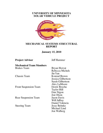
UNIVERSITY OF MINNESOTASOLAR VEHICLE PROJECTMECHANICAL SYSTEMS STRUCTURALREPORTJanuary 15, 2010Project AdvisorMechanical Team MembersBrakes TeamChassis TeamFront Suspension TeamRear Suspension TeamSteering TeamJeff HammerBryan HorvatRebecca MichelsJin YanKonrad BrownJessica GilbertsonSarah GilbertsonAlex LaMooreDerek BrochuTaylor HillDan NigonJon OlsonJason DavisWill JaffrayDaniel ValenciaJesse BehnkeMichael LindJon Walberg
Table of ContentsIntroduction3Chassis / Roll Cage4Impact Analysis9Brakes15Front Suspension16Rear Suspension19Steering21AppendixChassisFront SuspensionRear Suspension2324262
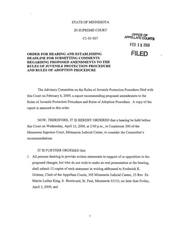
1 – Introduction/OverviewSince 1990, the University of Minnesota Solar Vehicle Project (UMNSVP) has producedeight world-class race vehicles. The newest car, Centaurus II, maintains the upright driverseating position introduced in the previous car while utilizing design innovations thatoptimize this layout.Image 1.1, CAD Image of Vehicle LayoutThe upright seating position used in the previous car improved visibility for the driver andincreased crush space at the rear of the car. A new chassis design for Centaurus IImaintains this seating position, while improving the CG of an upright seating layout andallowing for increased ground clearance and ample crush space. Fiberglass panels wereused to construct this chassis due to their excellent strength-to-weight ratio, fractureresistance and electrical resistance over carbon fiber.The suspension system has been modified to accommodate the higher ground clearancewhile maintaining excellent stability and minimizing tire scrub. The steering system hasbeen designed to allow the driver more freedom of movement for safer egress and brakingover the previous car. The braking and rear suspension systems are based on conceptsproven reliable in previous UMNSVP cars, optimized for the Centaurus II layout.It is the intent of this report to document the features of these mechanical systems and theengineering design and analysis utilized in their development. This report will demonstrateto NASC race officials that our entry is a safe, road-worthy, and competitive vehicle. Anyquestions or concerns regarding the content of this report may be addressed to either ourmechanical team lead or faculty advisor.Taylor Hill,Mechanical Team Lead3
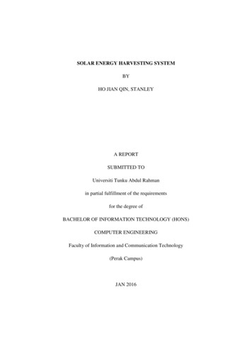
2 – Chassis and Roll Cage2.1 - IntroductionContinuing with the University of Minnesota’s tradition of building composite chassis’,Centaurus II’s chassis is constructed from a fiberglass composite. The composite frameaccounts for roughly 30 [lbs] of the total vehicle weight of 600 [lbs]. The battery ismounted at the very front of the car to balance out the weight of the driver beingconcentrated towards the rear of the car while still allowing for an acceptable center ofgravity. In an effort to build a high ground clearance car and decrease the aerodynamicdrag, the driver actually sits below the bottom panel of the chassis. This can be seen inFigure 2.1 below. Since the driver sits below the bottom plane of the shell, as an extraprecaution, a Kevlar lay-up was done on the inside and outside of the ‘butt bucket’ areawhere the driver sits.Figure 2.1 shows the location of the battery with respect to the driver compartment aswell as most of the mechanical systems of the car and how they attach to the compositechassis.Figure 2.1: ChassisThe chassis includes a composite frame integrated with the bottom of the vehicle shell,suspension components and roll cage. The top shell is completely detachable from thechassis to allow for redirection of the array while the car is stationary. There is also ahinged canopy above the driver compartment to allow for driver egress.While seated in the driver compartment, the driver is completely isolated from all movingcomponents of the car and the road. The driver compartment contains a 6-point harness,headrest and ventilation system. It was built to allow adequate visibility while drivingthe vehicle, as well as enough room to allow for safe handling of the vehicle.4
2.2 - Mounting to Composite PanelingTwo-part 5319 SERA aluminum inserts (grommets) are used everywhere that requiresvehicle components to be fastened to the composite chassis panels. The inserts aredesigned to handle a bolt-clamping load while distributing shear and axial loads to thecomposite panel sandwiched between the two parts of the insert. Also, 3MTM ScotchWeldTM DP-460 NS is used to glue the grommets into the composite paneling, whichincreases their shear strength dramatically. These inserts have been successfully used onall previous U of M solar vehicles and have been tested on our chassis panels to 1600[lbf]of in-plane shear.2.3 - ConstructionFiberglass paneling was chosen over Kevlar, carbon fiber and other materials for thechassis mainly because of its high strength to weight ratio and low electrical conductivity.Since fiberglass does not conduct electricity, it makes for an ideal material to attach all ofthe electrical components of the car to. Also, the composite panels allow for the driver tobe completely isolated from all moving parts of the car and the road.All of the 4.0 [ft.] by 8.0 [ft.] chassis panels were cut down to size using a high-pressurewater jet. The panels are assembled in a box-beam geometry with the majority of thepanels assembled perpendicular to each other. The panels also have interlocking tabs andslots at all structural joints for improved strength, accurate assembly and consistent highquality joints. A full scale mockup of the chassis and roll bar were constructed to verifydriver ingress and egress.2.4 - Material SpecificationsTeklam N505-1 prefabricated fiberglass paneling was used to construct the chassis. Thepanels have a thickness of 0.50 [in.]. The honeycomb core is made of Nomex with 1/8[in.] cell diameter. Each side of the core is covered with 1-ply of fiberglass.The paneling has an average weight of 0.33 [lbs/ft2]. Information was taken from Teklamdata sheets and testing procedure documents to determine the maximum allowable stressin the skin of the panels to be 32,970 [psi]. See the appendix A2 for calculations.5
Figure 2.2: DP-460 NS Joint3MTM Scotch-WeldTM DP-460 NS was used to join all of the chassis panels together. Theepoxy is rated at 4900 [psi] under room temperature curing and with the surfacepreparation conditions used. Typical joints on the car have a shear area per joint inch of0.5 [in2]. Knowing this, the joint can be assumed to carry a maximum shear load of(0.5in)*(4900psi) 2450 [lbf] per inch of joint. See Figure 2.2.2.5 - Crush SpaceNASC regulations require 15 [cm] of horizontal distance between the driver’s shoulders,hips and feet and the cars outermost surface. The minimum crush space of Centaurus II is24 [in]. In a rear collision, there would be 60 [in] of crush space from the trailing edge ofthe shell to the back of the driver compartment. In the event of a side collision, the driverresides in the center 22 [in] of the total 70 [in] wide car leaving 24 [in] of crush space oneither side of the driver compartment. During a front collision, having the battery at thevery front of the car helps block penetrating objects as well as decelerates the impactingbody due to its mass. In addition, there is 80 [in] of crush space from the leading edge ofthe car to the driver’s feet.2.6 - Driver CompartmentThe driver compartment was designed to be 22 [in] wide in order to allow the driver tomove freely enough to safely handle the car while driving, but also to keep them fromshifting excessively in the event of an impact. The chassis top panel is located 18 [in]above where the driver actually sits. This would be beneficial in the event of a crashbecause the majority of the driver’s body is encompassed in the structural chassis panels.The driver’s shoulders and head are the only parts of the driver outside of the chassis,both of which are protected by the roll cage, which is mounted to the top panel of thechassis.6
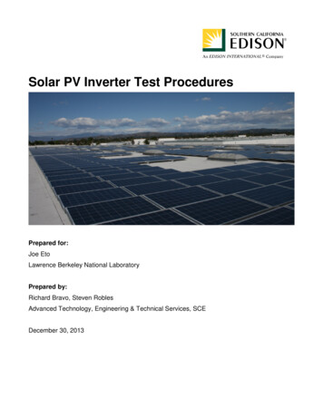
Figure 2.3: Driver compartment: Front, Side and Top Views2.7 - Safety HarnessA 6-point safety harness is installed into the driver compartment in order to protect thedriver in case of a collision. The rear harness attachment points are to a horizontal tube(see Figure 2.3) that is integrated into the roll cage as a part of the rear roll hoop. Theseat back is reclined such that it abides by the 27 degree maximum driver seating angle.The front harness attachment points are at the very bottom of the driver compartmentpositioned so that the belt crosses the driver’s hips. This attachment point is part of anangled bracket that is installed via grommets to both the bottom panel and the side panelof where the driver is seated (seen as a small green bracket in Figure 2.3 – side view)2.8 - Roll CageFigure 2.4: Roll Cage Components7
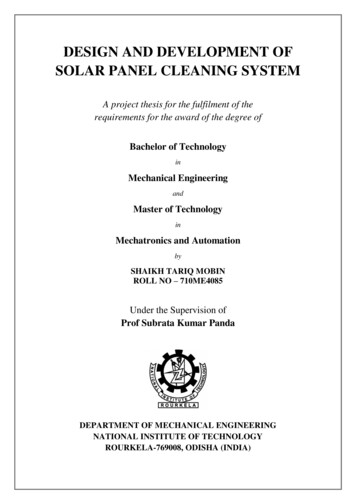
The roll cage is composed of 5 main parts:Front hoop (blue): The front hoop is located in front of the driver and extendsfrom the top chassis panel to just above the driver’s head. It will protect the driver bydeflecting any moving bodies such as the shell or canopy during an impact. Directlybeneath the front hoop is a bulkhead that acts as a lift-point on the car as well as a rigidsupport for the roll cage.Rear hoop (blue): The rear hoop is located 12.5 [in.] behind the front hoop at theback of the driver compartment opening. The attachment point to the chassis is locateddirectly above the vertical chassis panels running the length of the car to ensure that thispoint is rigid.Forward slanting braces (green): The purpose of the forward slanting braces isto cover the driver’s hands and steering wheel and also to give strength to the structurewhen force is applied in the fore-aft direction. The forward most point of this roll cagecomponent attaches to the chassis directly above the vertical chassis panels running thelength of the car.Horizontal center braces (yellow): The horizontal center braces were placed justbelow the driver’s sightline. They connect the front and rear hoops and act to stabilizethe structure while taking some of the load in an impact.Center cross braces (green): The center cross braces act to decrease the largemoment created in an impact due to the yellow horizontal braces being placed below thedriver’s sightline.The roll cage is constructed from 1.250 [in.] outer diameter 4130 steel tubing of threedifferent wall thicknesses. Shown in Figure 2.4, the green colored tubing represents awall thickness of 0.035 [in.], the yellow colored tubing a wall thickness of 0.049 [in.] andthe blue colored tubing a wall thickness of 0.083 [in.]. The tubing has a yield strength ofapproximately of 75,000 [psi]. The mounting brackets that attach the roll cage to thechassis top panel are made from 0.0625 [in.] 4130 steel sheet stock. All roll cagecomponents were welded by professionals using the TIG welding process.8
3 - Impact Analysis3.1 - Total Mass and Center of GravityCoordinateReferenceXYZComponentChassis PanelsShellBatteriesFront SuspensionRear SuspensionSteeringBrakesRoll CageDriverEEArrayTotalCenterlineGroundForward of Front AxleMass 2.1WeightDistributionFront63.5%Rear36.5%Y 7.7Z .5-32.8The distance between the center of gravity of the vehicle and the centerline of the car (xplane) can be neglected since all of the components with dominant mass have a center ofgravity on the centerline of the car. Some smaller miscellaneous components of the carwere not included in the table above and therefore the car with driver is estimated as 600[lbs] for stress and force calculations. The longitudinal and vertical placement of thecenter of gravity contributes to the tip over stability of the vehicle. At 17.7 inches fromthe ground, the car will skid in a severe cornering maneuver well before it will tip over.3.2 - Front ImpactIn the event of a frontal collision, the nose of the shell would be crushed first followed bythe battery and front of the chassis. There is then approximately 34 [in.] of chassis thatwould need to be crushed before the impacting body reached the driver’s feet. Thechassis and bulkheads at the front of the car extend from 12 [in.] to 23.3 [in.] above theground plane; this easily accommodates the bumper height range given in the raceregulations of 13.8 [in.] to 17.7 [in.]. Thus, in the event of a collision, the bumper of animpacting vehicle would transfer its forces directly to the structural chassis and bulkheadsof the car. If the latches attaching the shell to the chassis were to fail causing the shelland array or the canopy to be pushed towards the rear of the car, the driver would beprotected by the front supports and front hoop of the roll cage. These roll cagecomponents would cause the top shell to deflect up and over the driver, leaving the drivercompartment unobstructed.9
The two vertical panels running the length of the car will take the majority of the forcefrom an impact. This is a conservative estimate because in reality, a portion of the forcewould be distributed through the top and bottom panel of the chassis that connect the twovertical panels. The following calculations were done using the conservative estimate ofonly the vertical panels taking the load.In a frontal impact, the two main modes of failure would be buckling or stress due tocompression. Only one of the vertical panels and not the entire box beam structure isconsidered with the following buckling calculation and therefore the result is a vastunderestimate of the total force required to cause the chassis to fail in buckling due to a5G frontal impact.The following equation for critical buckling force was obtained from SuccessfulComposite Techniques, by K. Noakes, where d is the distance between median planes ofthe fiberglass skin, b is the height of the panel, E is the elastic modulus and K is theempirical buckling stress coefficient. The value for K was obtained from CompositeMaterials: Design and Applications, Second Edition, by D. Gay." d %2" 0.49in % 2f b ' EK ' ( 4.25E6 psi)(1.0) 9618.5lbs# b&# 10.3in &!The critical buckling force as calculated above is 9618 [lbs], which is 3.2 times the totalforce of 3000 [lbs] applied during a 5G frontal impact.To find the stress due to compression in the panels from a 5G front impact, the equationσ F/A was used. Where area is the area of the fiberglass skin on the two vertical panelsrunning the length of the car; A 4*10.3in*0.01in 0.412 in2. The compressive stressproduced in the panels was calculated to be σ F/A (5*600lbs)/0.412in2 7281.5[psi]. This yields a safety factor of 4.5 with respect to the critical stress of the fiberglassskins.With a safety factor of 3.2 for failure due to buckling and a safety factor of 4.5 for failuredue to compressive stresses, it can be concluded that the chassis can easily withstand a5G front impact.3.3 - Rear ImpactThe height of the trailing edge of the vehicle’s shell is 16 [in.], which is between thebumper height of 13.8 [in.] and 17.7 [in.] given by the regulations. This ensures that thetrailing edge of the shell and array would be the first to be crushed upon a rear impact.The impacting body would then reach the rear suspension and the back of the chassishaving a height ranging from 12 [in.] to 23.3 [in.], and finally the rear roll cage hoop. Thecrush space from the trailing edge of the car to the rear hoop of the roll cage totals 60[in.].In the event of a rear impact, the two modes of failure for the chassis would be the sameas with a front impact, buckling or stress due to compression. Because the geometry ofthe chassis is the same in the front of the car as in the rear, the values for critical buckling10
force and stress due to compression would be the same as described in the front impactportion. Since it was proven that the chassis could withstand a 5G front impact, it cantherefore be assumed that the chassis could safely withstand a 5G impact from the rear.3.4 - Bending Rigidity Under Vertical LoadingIf we assume that the weight of the car is concentrated at the center of gravity, thisproduces a maximum moment of M FF*LCG , where FF is the portion of the total weightof the car supported by the front suspension and LCG is the distance from the frontsuspension to the center of gravity of the car.M FF LCG [(Wt total " Wt FS " Wt RS ) # 0.635] # 32.8in 10,476in lbs" My 10,476in # lbs 7.467in 2,935.4 psiI26.65in 4!!The value for y and I were calculated based upon the area of the chassis that had thelowest moment of inertia – the front of the driver compartment where the top chassispanel is cut out. Also, these values were calculated just accounting for the skin of thecomposite panels as having inertia.According to the calculations above, under static loading conditions the chassis has asafety factor of 11.2 with respect to failure. In the case of a roll over or a large bump (5Gloading), there is a safety factor of just over 2.2.3.5 - Side ImpactThe driver resides in the center 22 [in] of the total 70 [in] wide car leaving 24 [in] ofcrush space on either side of the driver compartment in the event of a side impact. If theimpact were to cause the array and/or canopy to come unattached, the front and rear rollcage hoops as well as the horizontal center supports would protect the driver’s head andupper body from being harmed. These roll cage components would cause the impactingbody to slide up and over the driver compartment.A side impact near the center of the side of the car will be considered because such animpact would create the largest bending moment and therefore the largest stresses in thechassis.The side impact can be treated similarly to the vertical loading scenario, just with adifferent moment of inertia with the 5G force acting horizontally instead of vertically onthe chassis. Since there is a structural chassis panel stretching across the chassis near boththe front and rear axle, both are treated as rigid supports with a 5G load applied at 32.4[in.] from the front axle.M 5 " FF LCG 52,380in # lbs" !!My 52,380in # lbs 17.25in 5166.1psiI174.9in 411
A maximum stress of 5,166.1 [psi] yields a safety factor of nearly 6.4 with respect tofailure due to a 5G side impact.3.6 - Rollover AnalysisIn a rollover situation the roll cage and chassis would support the vehicle. Any loadsapplied to the roll cage would be transferred to the chassis in such a situation. Since ithas already been proven that the chassis can withstand greater than 4G loading, the rollcage attachment points to the chassis are treated as rigid in the following analysis.Roll cage simulations were done using finite element analysis. The software packageused was ANSYS Workbench version 11. All simulations done were static structuralusing tetrahedral elements with a relevance factor of 60. All loads were applied solely tothe front hoop of the roll cage as a worst case scenario situation. During most rolloversituations, the load would be shared by either the front of the chassis and the front hoopor both the front and rear hoop. With the possibility of the front hoop taking the entireload, this was treated as the loading situation. Stresses were calculated using theequivalent (von-Mises) stress model. A vehicle weight of 600 [lbs] was used in all of theroll cage simulations. All of the simulations to follow include an isometric view of theequivalent stress result as well as a close-up image of the area of highest stress.3.7 - 4G Vertical LoadFor this loading condition, the highest stresses were found near where the center crossbraces attach to the front hoop. Since this is where the largest bending moment isoccurring, it seems logical that the maximum stress would be found here. The higheststress seen was 24,738 [psi], leaving a safety factor of just over 3 with respect to the yieldstrength of 4130 steel, which is 75,000 [psi].12
3.8 - 4G Load, 22.5o Forward from VerticalThe highest stresses for this loading scenario were found where the center cross bracesattach to the horizontal center braces. Since the front and rear hoops are constructed fromlarger wall thickness tubing than the horizontal braces, it seems logical that the higheststress would be found at this intersection and not where the center cross braces attach tothe front hoop. These two places are where the bending moment induced by the 4Gloading was the highest. The highest stress found was 46,066 [psi]. This value is inbetween the values of maximum stress found for the vertical loading and the forward 45oloading scenarios, which is intuitive since the 22.5o angle that the load was applied at isbetween the 0o and 45o load. The maximum stress in this loading condition yields asafety factor of 2.3.3.9 - 4G Load, 45o Forward from VerticalAs can be seen in the above-right image, the highest stresses for the 45o from verticalloading scenario were found around where the center cross brace attaches to thehorizontal brace. This is the same place that the highest stress was found with the 22.5oforward loading condition. With this kind of geometry, the maximum stress should befound in the same general area for these two loading conditions. The larger rearward13
component of the impact force causes the stress in this situation to be greater than in the22.5o situation. The maximum stress found was 58,732 [psi], which leaves a safety factorof 1.3 with respect to yielding.3.10 - 4G Load, 22.5o Lateral from VerticalThe maximum stress found in this loading scenario was 46,066 [psi], which yields asafety factor of just over 1.6. This value seems logical since a force applied at 22.5oshould produce a stress somewhere in between the stress produced from a force at 0o and45o from lateral.3.11 - 4G Load, 45o Lateral from VerticalThe areas of maximum stress for this loading condition were the area near where thefront hoop and center cross braces attach as well as the area where the front hoop attachesto the chassis. These two areas are where the largest bending moments are created due tothe 45o lateral force. The maximum stress created was 58,862 [psi]. This leaves a safetyfactor of 1.3 with respect to yielding of the roll cage in a rollover situation.14
3.12 - Battery EnclosureThe battery box is made using the same construction as the chassis. The box isremovable and attached to the chassis side panels via four grommets. Loading these fourgrommets in shear supports the weight of the box. There is a horizontal panel directlybelow the battery box that is tabbed into the side panels of the chassis to add torsionalstrength to the system as well as to aid in supporting the box. Between the battery andthe driver compartment are the back panel of the battery box, the power tracker boxes,and the front panel of the chassis. Therefore, at least 4 panels would need to bepenetrated before any of the batteries were to contact the driver.The cells are secured inside the box using 3MTM Hi-Strength 90 Spray Adhesive. Thissystem has been proven on Borealis III and Centaurus I, and provides a measure ofvibration resistance for the fragile electrical connections between cells. Battery coolingis accomplished through the use of eight 60 [mm] fans. The air is then vented out of boththe left and right wheel well.4 - Brakes4.1 – System SpecificationsCentaurus II uses two independent hydraulic braking systems. The mechanical braking isassisted by regenerative braking through the motor at the rear wheel.Figure 4.1: The master cylinder and pedal assembly as viewed from above the chassisEach hydraulic system has a master cylinder with a 0.75 [in] diameter piston whichactuates a caliper cylinder at each front wheel. The master cylinders are supplied fromCNC, Inc, and are made out of aluminum with steel sleeves. The calipers are supplied15
from Martin Custom Products and have 1.00 [in] diameter pistons. There is a custom8.000 [in] diameter brake disc at each of the front wheels. The discs will be machinedfrom 7075-T6 Aluminum and Alpha coated by Surface Solutions in Fridley, MN. Alphacoating produces a hard, wear resistant surface. A custom pedal assembly actuates bothhydraulic systems simultaneously and is adjustable to balance wear on the pads. Theregenerative brake is controlled with a lever on the steering wheel. Lock-nuts are used onbolts where there are no turning parts and castle nuts with either cotter pins or safety wireare used on the bolts fastened to rotating parts.4.2 - Loading Conditions/System AnalysisThe braking system is designed to be limited only by friction between the tires and theroad. A pedal force of 100 [lbf] will supply line pressure of 176.8 [psi] and producedeceleration of 0.50 [G]. The master cylinders are rated for 1200 [psi]. If one hydraulicsystem fails, there will still be a working caliper on each wheel and the pressure in theremaining system at 100 [lbf] of driver input force would double to 353.6 [psi] which isstill below the rated value. The pedal will be constructed from 0.5 [in] x 1.25 [in] 7075T6 aluminum, and machined into a modified I-beam design. The maximum bendingstress of the pedal under double the required force (200[lbf]) results in a safety factor of1.81.The master cylinder and pedal assembly will be mounted on top of the chassis where thepedal enters into the driver compartment from the top as shown in Figure 4.1. Theassembly is mounted to the chassis using six 5319 SERA aluminum inserts as describedin section 2.2. A pedal force of 200 [lb] results in a 705.6 [lb] reaction loading the sixbolts and grommets in shear on each bracket. There is also a moment produced that loadsthe six grommets well below their tested strength. The main master cylinder bracket willbe water jet cut from 6061-T6 Aluminum, and bent to the shape shown in Figure 4.1.5 – Front Suspension5.1 - Materials and LayoutThe front suspension is arranged in a double a-arm layout designed to minimize tire scruband weight. The lower a-arms are made of 0.750 [in] OD by 0.058 [in] wall thickness4130 steel tubing. The upper a-arms are machined into a 0.5 [in] by 0.5 [in] section from7075-T6 Aluminum. Both sets of a-arms use Aurora Bearing rod ends (HXAM-4T) on thechassis side and Aurora spherical bearings (HAB-4T) on the upright side. The brackets forboth sets are made from 6061-T6 aluminum. The front suspension uses Army/Navy ormilitary spec nuts, bolts and washers. All structural brackets are secured to the chassis withat least 3 bolts and 5319 SERA aluminum inserts (section 2.2).16
Figure 5.1: CAD Image of Front Suspension, Steering Not Shown5.2 - Wheels, Tires, Hubs, and AxlesWe will be using NGM wheels with Bridgestone Ecopia EP-80 tires. From section 3.1,the weight carried by the front wheels is 178 [lb] each, and by the rear wheel is 205 [lb].These weights are well within the load rating of the tires. The left side hub uses a LHthreaded nut, and the right side hub uses a RH threaded nut to ensure retention. All hubnuts utilize safety wire to prevent loosening. All components in this section are identicalto those used by the UMNSVP on our past 2 vehicles raced in NASC without incidencewith a near identical car weight.See Appendix (A5) for force calculations used in the following stress analyses5.3 - A-Arm Buckling AnalysisA buckling analysis of the upper and lower A-arms gives the following critical loads. Fora more detailed description of the analysis used, please refer tohttp://www.engineersedge.com/column buckling/column ideal.htmUpper A-arm Critical NumbersWidth, W 0.50 [in.] (at minimum)Height, H 0.50 [in.]Length, L 10.23 [in.]Material 7075 T-6 AluminumE 1.04E 7 psiYield Stress, σy 67E 3 psi17
CalculationsMoment of Inertia,Cross Sectional Area,Radius of Gyration,Slenderness Ratio,Critical Slenderness Ratio,54.3Therefore, we use Johnson’s Equation for a short beam.Critical Load,1430 [lbf]Calculated Worst Case Compressive Load 480 [lbf]Safety Factor 2.98Lower A-arm Critical NumbersOuter Diameter, OD 0.75 [in.]Thickness, t 0.058 [in.]Length, L 18.29 [in.]Material 4130 SteelE 3.00E 7 PsiYield Stress 75E 3 PsiCalculationsMoment of Inertia,Cross Sectional Area,Radius of Gyration,Slenderness Ratio,Critical Slenderness Ratio,Critical Load,71.73320 [lbf]Calculated Worst Case Compressive Load 1426 [lbf]Safety Factor 2.335.4 - Upright Stress AnalysisThe stress analysis for the upright was done with Pro/Engineer Mechanica, a brand offinite element analysis. The upright is made from 7075-T6 Aluminum with a yield stressof 73 [ksi]. The results when loaded with the calculated forces (section A5) are shown inthe figure below.18
The maximum von Mises stress is 45 [ksi] giving a safety factor of 1.622 undersimultaneous 4G bump, 1G braking and 1G cornering.6 – Rear SuspensionABCFigure 6.1: CAD Image of Rear Suspension19
6.1 – Materials SpecificationsThe rear suspension system utilizes a swing arm design similar to that used for theprevious car. The swing arm is made of 1.75 [in.] OD by 0.083 [in.] wall thickness 4130steel tubing with a 1.25 [in.] OD bracing arm and motor mount milled out of 4130 steel.The swing arm tubes and motor mount are professionally welded using the TIG processinto the layout illustrated in Figure 6.1, where the swing arm is in black, and the motormount in orange.The swing arm is attached to the chassis through brackets machined out of 7075-T6Aluminum. Each bracket contains bearings and is attached to the chassis using five 5319SERA aluminum grommets (section 2.2). Each grommet can handle 1500 [lbs] of shearload, so that the combined grommets of each bracket can easily support the maximum loadsapplied at the mounting points of the swing arm.The swing arm is also connected to the chassis via a Fox Float RC shock, mounted to theswing arm with a bracket machined out of 4130 steel, and to the chassis with twobrackets made from 6061-T6
6 Figure 2.2: DP-460 NS Joint 3MTM Scotch-WeldTM DP-460 NS was used to join all of the chassis panels together. The epoxy is rated at 4900 [psi] under room temperature