Transcription
RASPBERRY PLC ETHERNET 21 I/OsANALOG/DIGITAL PLUSRASPBERRY PLC ETHERNETI/Os ANALOG DIGITAL PLUS
Ref. 012002000200Rev. 0: 02-09-20201
Ref. 012002000200Rev. 0: 02-09-2020RASPBERRY PLC ETHERNET 21 I/OsANALOG/DIGITAL PLUS Quick User GuideRevised, September 20202
Ref. 012002000200Rev. 0: 02-09-2020PrefaceThis User Guide is been implemented by Boot & Work, S.L. workingunder the name Industrial Shields.Purpose of the manualThe information contained in this manual can be used as a reference to operate andget a better understanding of the technical data of the signal modules, power supplymodules and interface modules.Intended AudienceThis User Guide is intended for the following audience: Persons in charge of introducing automation devices.Persons who design automation systems.Persons who install or connect automation devices.Persons who manage working automation installation.Warnings: Unused pins should not be connected. Ignoring the directive may damage thecontroller.Before using this product, it is the responsibility of the user to read the product’s UserGuide and all accompanying documentation.Industrial Shields PLCs must be powered between 12Vdc and 24Vdc. If a higher voltageis supplied to the equipment can suffer irreversible damage.Maintenance must be performed by qualified personnel familiarized with theconstruction, operation, and hazards involved with the control.Maintenance should be performed with the control out of operation and disconnectedfrom all sources of power.The Industrial Shields Family PLCs are Open Type Controllers. It is required that youinstall the Raspberry PLC in a housing, cabinet, or electric control room. Entry to thehousing, cabinet, or electric control room should be limited to authorized personnel.Inside the housting, cabinet or electric control room, the Industrial Shields PLC must beat a minimum distance from the rest of the components of a minimum of 25 cm, it canbe severely damaged.Failure to follow these installation requirements could result in severe personal injuryand/or property damage. Always follow these requirements when installing Raspberryfamily PLCs.3
Ref. 012002000200 Rev. 0: 02-09-2020In case of installation or maintenance of the PLC please follow the instructions markedin the Installation and Maintenance section on the User Guide.Do not disconnect equipment when a flammable or combustible atmosphere ispresent.Disconnection of equipment when a flammable or combustible atmosphere is presentmay cause a fire or explosion which could result in death, serious injury and/orproperty damage.Inside the encapsulated, there are supercapacitors if 25F which can be dangerous. Becareful with them.4
Ref. 012002000200Rev. 0: 02-09-2020Table of ContentsGeneral Description RASPBERRY PLC ETHERNET I/OS ANALOG/DIGITAL PLUSProduct . 7Zone - Nomenclature . 7Zone Distribution. 8A Zone Features. 80 Zone Features . 9Mechanical dimension . 9General Features . 10Technical Specifications: . 11General Specifications: . 11Performance Specification: . 11Symbology . 12Precautions. 13Raspberry Board . 13Intended Audience . 13General Precautions . 13How to connect PLC to power supply . 14How to access to the Raspberry PLC . 15Raspberry PLC access . 155.1.1Linux . 155.1.2Windows. 17How to change the IP . 19Linux . 19Windows. 19Raspberry PLC Family Pinout. 210 Zone connection (Communications) . 21A Zone connection (I/Os) . 1Switch Configuration . 2A Zone . 2I/O RASPBERRY PLC 3.3V pins . 35
Ref. 012002000200Rev. 0: 02-09-2020Serial – RX/TX . 3SPI0 – MISO/MOSI/SCK . 3GPIO25 . 4Equivalence Table. 5Pinout Equivalence . 5Inputs. 5Outputs. 5Internal I2C and SPI Connections . 1Input & Output control . 1Set Value. 1Get Value . 2A & B Zone Features: Communications & RTC & uSD . 2RS-485 . 2I2C. 2SPI . 1TTL . 1Ethernet. 1RTC. 1uSD . 1Revision Table . 26
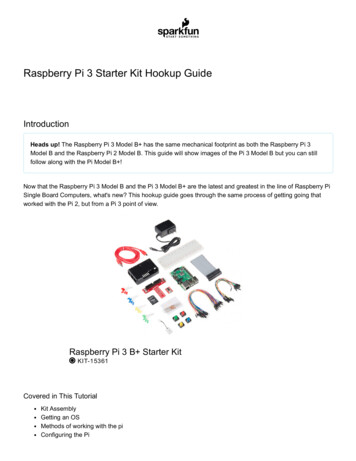
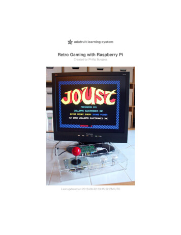
Ref. 012002000200Rev. 0: 02-09-2020General Description RASPBERRY PLC ETHERNET I/OSANALOG/DIGITAL PLUS ProductZone - NomenclatureThe nomenclature shown in this point will be used in the whole User Guide, so it isimportant to understand this nomenclature.A ZONE0 ZONE0 ZONEA ZONEThe nomenclature to differentiate the zones is based on Alphanumeric values, being 0the internal communication shield and A the I/Os shield.A ZONE0 ZONE The inputs in the zone A are named I0.X, being X any number suitable in theShield. Outputs are named as Q0.X.7
Ref. 012002000200Rev. 0: 02-09-2020Zone DistributionThe distribution of the different features that provide the Raspberry Ethernet 21 I/OsPLUS are described below.A Zone FeaturesShieldC Zone13 Inputs(13 Digital inputs,6 of which canwork as AnalogInput)Analog Shield8 Outputs(8 Digital Outputs,3 of which canwork as AnalogOutput)8
Ref. 012002000200Rev. 0: 02-09-20200 Zone FeaturesShieldCommunicationShieldA Zone(2x) Ethernet(4x) USB(1x) I2C(1x) TTL(2x) HALF Duplex RS-485(1x) SPI external Port(1x) RTC(1x) Bluetooth(1x) WiFi(1x) μSD Socket(1X) CAN(x1) μHDMIMechanical dimension9
Ref. 012002000200Rev. 0: 02-09-2020General FeaturesCONECTABLE PLC ARDUINO 24 VCC M-DUINOMODEL TYPEGRPS/GSM Controller GeneralSpecificationsInformationInput Voltage12 to 24 VdcFuse Protection (2.5 A) PolarityprotectionI max.1.5 ASize101x70.1x119.5Clock Speed1.5 GHzFlash Memory-SRAM2 - 4 - 8 GBCommunicationsI2C – Ethernet (x2) – USB (x4) – (x2) RS485 – SPI – WiFi –Bluetooth - Serial TTL – CAN - μSD - RTCDigital GPIO25(3.3 V)MAX485 – W55003.3 V0 to 10VacRated Voltage: 10VacAn/Dig Input 10bit(0-10Vcc)Digital Isolated Input (24Vcc)5 to 24VdcI min: 2 to 12 mAGalvanic IsolationRated Voltage: 24 Vdc5 to 24VdcI min: 2 to 12 mAGalvanic IsolationRated Voltage: 24 Vdc(24Vcc)5 to 24VdcI min: 2 to 12 mAGalvanic IsolationRated Voltage: 24VdcExpandabilityI2C – 127 elements – Serial Port RS485* Interrupt isolated Input HS* By using this type of signal can no longer use Digital signal (24Vdc)10
Ref. 012002000200Rev. 0: 02-09-2020Technical Specifications:General Specifications:ItemRASPBERRY PLC ETHERNET 21 I/Os PLUSPower supplyvoltageDC power supplyOperatingvoltage rangeDC power supply11.4 to 25.4VdcPowerconsumptionDC power supply30 W max.Externalpower supply12 to 24VdcPower supplyvoltage24 VdcPower supplyoutput capacity700 MaInsulation resistance20MΩ min.at 500Vdc between the AC terminals and the protective earth terminal.Dielectric strength2.300 VAC at 50/60 Hz for one minute with a leakage current of 10mA max. Between all theexternal AC terminals and the protective ground terminal.Shock resistance80m/s2 in the X, Y and Z direction 2 times each.Ambient temperature (operating)Ambient humidity (operating)Ambient environment (operating)Ambient temperature (storage)Power supply holding timeWeight0º to 50ºC with Raspberry OS Lite / 0º to 40º with Raspberry OS Desktop10% to 90% (no condensation)With no corrosive gas-20º to 60ºC2ms min.378g max.Performance Specification:Raspberry BoardI/O control methodProgramming languageRaspberry Pi 4Combination of the cyclic scan and immediate refresh processing methods.Linux applications: Python, C , etc.Program capacity (SRAM)2 – 4 - 8 GBEEPROM4 MB/512 KBClock SpeedCPU1.5 GHzBroadcom BCM2711, Quad core Cortex-A72 (ARM v8) 64-bit SoC @ 1.5GHz11
Ref. 012002000200Rev. 0: 02-09-2020SymbologyTable that includes all the symbology that is used in the serigraph of the RASPBERRY PLCETHERNET I/OS ANALOG/DIGITAL PLUS:SymbolStandard No. /Standard TitleIEC 60417 /Graphical symbolsfor use onequipmentIEC 60417 /Graphical symbolsfor use onequipmentIEC 60417 /Graphical symbolsfor use onequipmentIEC 60417 /Graphical symbolsfor use onequipmentIEC 60417 /Graphical symbolsfor use onequipmentMedical DevicesDirective93/42/EECISO 7000/Graphical symbolsfor use onequipmentISO 7000/Graphical symbolsfor use onequipmentStandardReference No. /Symbol TitleSymbol Meaning5031 / DirectCurrentIndicates that the equipment issuitable for direct current only;to identify relevant terminals5032 / AlternatingCurrent5130 / PulseGeneral5017 / Earth,GroundIndicates that the equipment issuitable for alternating currentonly; to identify relevantterminalsTo identify the control bywhich a pulse is started.To identify an earth (ground)terminal in cases whereneither the symbol 5018 nor5019 is explicitly required.5115 / Signal lampTo identify the switch bymeans of which the signallamp(s) is (are) switched on oroff.CE MarkingCE marking indicates that aproduct complies withapplicable European Unionregulations0434B /Warning symbolIndicates a potentiallyhazardous situation which, ifnot avoided, could result indeath or serious injury5036 / DangerousVoltageTo indicate hazards arisingfrom dangerous voltages12
Ref. 012002000200Rev. 0: 02-09-2020PrecautionsRead this manual before attempting to use the RASPBERRY PLC ETHERNET I/OSANALOG/DIGITAL PLUS and follow its descriptions for reference during operation.Raspberry BoardThe RASPBERRY PLC ETHERNET 21 I/Os ANALOG/DIGITAL PLUS includes a Raspberry Pi 4 Boardas controller.Intended AudienceThis manual is intended for technicians, which must have knowledge on electrical systems.General PrecautionsThe user must operate Raspberry PLC according to the performance specifications described inthis manual.Before using the RASPBERRY PLC EHTERNET CPU under different conditions from what hasbeen specified in this manual or integrating into nuclear control systems, railroad systems,aviation systems, vehicles, combustion systems, medical equipment, amusement machines,safety equipment and other systems, machines, and equipment that may have a seriousinfluence on lives and property if used improperly, consult your INDUSTRIAL SHIELDSrepresentative. Ensure that the rating and performance characteristics of the Raspberry PLCare sufficient for the systems, machines, and equipment, and be sure to provide the systems,machines, and equipment double safety mechanisms. This manual provides information forprogramming and operating the Raspberry PLC.13
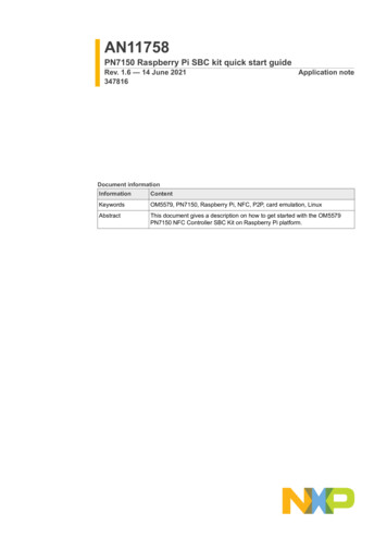
Ref. 012002000200Rev. 0: 02-09-2020How to connect PLC to power supply-Raspberry PI Family PLCs are 12-24Vdc supplied. IMPORTANT: The polarity IS NOTREVERSAL!-Make sure that the live and GND connector of the power supply match the PLC.-Make sure that the power supply mains output is not higher than 24Vdc.-Suggested power suppliersCompact DIN rail power supply. Assembled on 35mmDIN Rail:-24Vdc-10A-240WIndustrial Shields power supplies provide paralleloperation, overvoltage protection, and overcurrentprotection. There is a LED inductor for power status,the power supply is certified according to UL.The standard, Part 1 of IEC 61010, sets the general safety requirements for the following typesof electrical devices and their accessories, regardless of where use of the device is intended.The equipment must be powered from an external power source in accordance with IEC61010-1, whose output is MBTS and is limited in power according to section 9.4 of IEC 610101.WARINING: Once the equipment is installed inside an electrical cabinet, the MTBS cables ofthe equipment must be separated from the dangerous voltage cables.14
Ref. 012002000200Rev. 0: 02-09-2020How to access to the Raspberry PLCRaspberry PLC accessTo facilitate the connection to the Raspberry PLC, our company has set a default IP for it. Forthe first time of use, an Ethernet connection between the Raspberry PLC and a PC will benecessary. The Raspberry is given with the local IP address 10.10.10.20/24, the default user ispi and the password is raspberry. For connecting to it, you must change your local address forbeing in the same local network as the Raspberry. After the first connection you can add usersor change each user’s password anytime. In order to know if the Raspberry is connected andthe Ethernet connection is going on, a ping command can be run on the terminal (for windowsusers enter cnm in the windows searching tab to open it):The steps to follow for both Linux and Windows are explained below:5.1.1LinuxIn order to access the Raspberry PLC, Linux users have to enter by SSH protocol, which shouldhave been installed before by the user. As has been said, the Raspberry is given with a local IPaddress by default for making an easier path for the customer. So, first of all we have to checkif our local Ethernet Network is set with the same local IP address as our raspberrian device. Incase that you do not know how to set it, check the section 6 of the guide. As have beenmentioned before, you can use the ping command with the address 10.10.10.20 as option: ping 10.10.10.20If the ping works successfully means that our connection is ready. If not you can check section6 again or read our blog about changing the local IP.For accessing to the Raspberry PLC we will run the command ssh shown below:15
Ref. 012002000200Rev. 0: 02-09-2020 ssh pi@10.10.10.20The connection will start, but first the password provided before will be required. If theusername and password are correct, you can start the SSH session.When an SSH connection is made for the first time, the server delivers the server's public keyto the SSH client. The system will alert you to this and offer you the option of accepting the keyor rejecting it. You have to accept the key, as it will be stored in the register and will be used tocontrast it with the one sent by the server on each connection. If for some reason the keychanges, a new notice is generated in which the authenticity of the received key will be raised,since someone could be posing as the server to which we want to connect.Once connected, will be a full access to the Raspberry PLC and the user will be able to controlit and set the functions needed. Also new users or the password could be changed as thedevice IP. The commands for going through the Raspberry are the same as the Linux terminal.The most useful are the following: cd: to navigate through the Linux files and directories.ls: is used to view the contents of a directory.cat: it is used to list the contents of a file on the standard output.mkdir: use mkdir command to make a new directoryrm: is used to delete directories and the contents within them.touch: allows you to create a blank new file.In order to logout and closing the connection, just type exit in the Raspberry terminal.16
Ref. 012002000200Rev. 0: 02-09-20205.1.2 WindowsFor the Windows users, we recommend using the open-source terminal emulator PuTTy sshclient. The latest release of PuTTY can be downloaded from the official web which containsdownload links for the latest released version of PuTTY.https://www.chiark.greenend.org.uk/ sgtatham/putty/latest.htmlFor connecting to it, you must change your local address for being in the same local network asthe Raspberry. You can use the ping command with the address 10.10.10.20 as option in thewindows terminal. The windows terminal can be found typing cnm on the windows search bar.After having installed PuTTY run the program and the following window should be opened. If itis not the same, click on the top left corner the option Session.For setting up PuTTY the Raspberry IP must be entered on the HostName field and make surethat the port 22 is being used and the SSH option is selected on the Connection Type. After allthe settings have been done, click on the Open button to run the program. For a faster start insubsequent sessions, before run the program, enter a name on Saved Sessions and click on theSave button (a double click on the named configuration will execute the program with thesaved configurations).17
Ref. 012002000200Rev. 0: 02-09-2020When you start the connection, the terminal window will be opened. Enter your username piand press Enter, then enter your password raspberry. If the username and password arecorrect, you can start the SSH session.When an SSH connection is made for the first time, the server delivers the server's public keyto the SSH client. PuTTy will alert you to this and offer you the option of accepting the key orrejecting it. You have to accept the key, as it will be stored in the register and will be used tocontrast it with the one sent by the server on each connection. If for some reason the keychanges, PuTTy will generate a new notice in which the authenticity of the received key will beraised, since someone could be posing as the server to which we want to connect.Once connected, will be a full access to the Raspberry PLC and the user will be able to controlit and set the functions needed. Also new users or the password could be changed as thedevice IP. The commands for going through the Raspberry are the same as the Linux terminal.The most useful are the following: cd: to navigate through the Linux files and directories.ls: is used to view the contents of a directory.cat: it is used to list the contents of a file on the standard output.mkdir: use mkdir command to make a new directoryrm: is used to delete directories and the contents within them.touch: allows you to create a blank new file.For closing the connection, just type exit in the Raspberry terminal.18
Ref. 012002000200Rev. 0: 02-09-2020How to change the IPTo access to the Raspberry PLC, the PLC must be on the same local network as the computerwhich we are working with. For changing the IP we must have connected our PC to an Ethernetconnection. By default, the computers are given an IP address of the 192.xxx.xxx.xxx or172.xxx.xxx.xxx type but will be necessary to change it to the 10.10.10.xxx as the PLC. As wewill work with an Ethernet interface, the WiFi interface IP must not be changed.LinuxFor changing the IP is not necessary to know the actual one that we have, but it is essential toknow the interface name on we are working. For knowing it, we will run a ip command withthe option a. ip aAll the PC’s interfaces will be shown and we will have to look for the one named enp as will bethe Ethernet one. In order to change it, we will use the “ifconfig” program, install if not bydefault in the system. To change your IP address on Linux, use the “ifconfig” commandfollowed by the name of your network interface and the new IP address to be changed on yourcomputer. This command have to be call being administrator, to be able to perform thecommand below, we need to use su or sudo command. sudo ifconfig interface name 10.10.10.1 netmask 255.255.255.0Now the IP should be changed. In order to check it, run again the ip a command. If not, repeatthe process or check out our website’s blog about changing the IP addresses.WindowsThe first step is to open the Control Panel. The quickest way to get to it is by clicking on Startand typing it. In the Control Panel, you can click on the Network and Internet category andthen click on Network and Sharing Center. If you are in icon view, just click directlyon Network and Sharing Center. An Ethernet connection must be shown, if not make sure thatthe Ethernet wire is connected to the Raspberry PLC.19
Ref. 012002000200Rev. 0: 02-09-2020Then we have to click on the Ethernet connection and a window about the state of it will beshown, where we can check all the details of the Ethernet connection. For changing the IP clickon the Properties button. Then search for Internet Protocol Version 4 (TCP/IPv4) and clickagain on the Properties button.Finally a window will be displayed where we will be able to change the IP address. Choose thesecond option and enter the following IP as the following image. Then choose Accept buttonand also in the Proprieties of Ethernet. Finally close the window and the IP will have beenchanged. In order to check it, click on the network details or run the ipconfig on the Windowsterminal. If not, repeat the process or check out our website’s blog about changing the IPaddresses.20
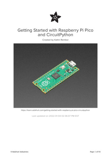
Ref. 012002000200Rev. 0: 02-09-2020Raspberry PLC Family Pinout0 Zone connection (Communications)Base(common unit)RaspberryPinA BGNDBA onPLCConnector0 ZoneCommunication wer SupplyPower SupplyGNDRASPBERRY PinPower SupplyGNDSPI/SSSPI/SSSPI/SSNot ConnectedRXTXPower SupplyGNDPower supply connectors(24Vdc – GND)SS: Chip Select pins. These pins can act as TTL, so they can work for the Chip Select pin of any device.Right SideUpper SideLeft Side21
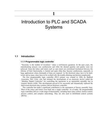
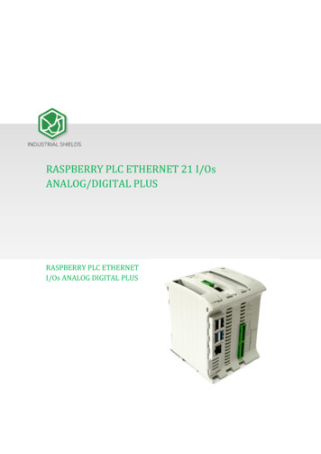
ETHERNET2 CONNECTORRTC BATTERYCAN BUSRev. 0: 02-09-2020POWER INDICATORRef. 012002000200A Zone connection 3GPIO13-FunctionI/Os I2C1RaspberryPLCConnectorA ZoneAnalog/ Digital InAnalog/ Digital InAnalog/ Digital InAnalog/ Digital InAnalog/ Digital InAnalog/ Digital InGND I0.6Interrupt 1 InGND I0.5Interrupt 0 InGND I0.4Digital InputGND I0.3Digital InputGND I0.2Digital InputGND I0.1Digital InputGND I0.0Digital InputAnalog/Digital InputsInterrupt Inputs (isolated)Digital Inputs (isolated)See section 10 table to check the internal connections.1
Ref. 012002000200Rev. 0: 02-09-2020Top ZoneLed indicator I/Os stateConfiguration Switch*(See section 7 to select the correctconfiguration for .51Q0.4Q0.3Q0.2Q0.1Q0.0FunctionI/Os I2C1RaspberryPLCConnectorA ZoneGND-GNDAnalog OutAnalog OutAnalog OutExternal Isolated Out VdcExternal Isolated Out GNDDigital/PWM OutDigital/PWM OutDigital/PWM OutDigital OutDigital OutDigital OutDigital OutDigital OutAnalog OutputsVoltage Supply/Reference forDigital/PWM Outputs (isolated)PWM/Digital OutputsSwitch ConfigurationA ZoneB 0.5For the Analog Shield if a switch is set to ON, it can only act as Digital Output. If it is set to OFFit can only act as an Analog Output.If it is desired to use a Digital Output the pin must be set to ON and the pin that will providethis digital output is represented with QX.X, being X any number of the tables above.If it is desired to use an Analog Output the pin must be set to OFF and the pin that will providethis analog output is represented with AX.X, being X any number of the tables above.2
Ref. 012002000200Rev. 0: 02-09-2020I/O RASPBERRY PLC 3.3V pinsThe RASPBERRY PLC ETHERNET I/OS ANALOG/DIGITAL PLUS has some of the Raspberry PI 4board pins available. These pins can be programmed according to Raspberry features such asI/O’s operating at 3.3V or any additional features present in the pins (for example I2Ccommunication in pins SCL and SDA). As these pins are directly connected to the Raspberry PI4 board, they are not as well protected as the normal inputs. These pins are mainly meant tobe used as prototyping.The Raspberry board available pins are summarized in the table below. In order to access tothese pins some extra considerations must be taken in consideration.PLC terminalTXRXMISO 0MOSI 0SCLK 0GPIO25Raspberry pinGPIO 14GPIO 15GPIO 9GPIO 10GPIO 11GPIO 25*IMPORTANT: Do not connect the terminals in the chart above to voltages higher than 3.3V.These terminals provide direct access to the Raspberry board.There are some special conditions depending on these 3.3V. Now it is going to be shown theconsiderations to operate with these pins.Serial – RX/TXThe Serial protocol can work also as a 3.3V pin. These pins should be used only in case that allthe 3.3V pins are already performing a function. If using both interfaces at the same time theRaspberry board will get blocked.These pins are not established with a pull-up or a pull-down configuration by default. TheArduino board allows the pins to be set in a pull-up configuration. Otherwise, an external pullup or pull-down circuit could be set.SPI0 – MISO/MOSI/SCKThese pins can only work as a 3.3V pins if the RS-485 protocol is not going to be used. As theRS-485 protocol uses the SPI to communicate with the Raspberry board, both behaviourscannot happen at the same time as the RS-485 would not work.These pins are not established with a pull-up or a pull-down configuration by default. TheRaspberry board allows the pins to be set either in a pull-up or pull-down configuration.Otherwise, an external pull-up or pull-down circuit could be set.3
Ref. 012002000200Rev. 0: 02-09-2020GPIO25GPIO25 is a Raspberry PI 4 GPIO pin that can be set as an input or output. It does not have anydefault function, so it can be configured without any restrictions. The pin is powered at 3.3volts; a higher voltage might be dangerous for the device.This pin is not established with a pull-up or a pull-down configuration by default. If the pin hasto be used, it might require a pull-up or pull-down configuration for prevention. The RaspberryPi 4 allows the pin to be set in both configurations; however, it can be set an external pull-upor pull-down circ
To facilitate the connection to the Raspberry PLC, our company has set a default IP for it. For the first time of use, an Ethernet connection between the Raspberry PLC and a PC will be necessary. The Raspberry is given with the local IP address 10.10.10.20/24, the default user is pi and the password is