Transcription
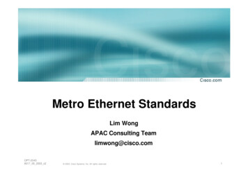
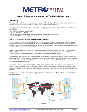
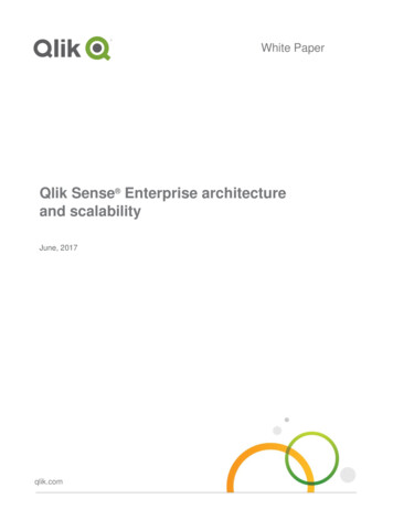
Scalability Analysis of Metro EthernetHeikki MahkonenHelsinki University of TechnologyEmail: heikki.mahkonen@piuha.netAbstract— This document gives a scalability analysis of MetroEthernet architecture. The purpose is to identify architecturalissues in Metro Ethernet Network (MEN) that are scalabilityconstraints when extending the carrier grade Ethernet serviceprovided by the MEN to a routed Ethernet service. The intentionof the scalability analysis presented in this document has notbeen to present detailed theoretical or mathematical analysis ofthe issues identified. The aim has been to identify the possibleconstraints for routed Ethernet service and give some exampleshow these issues could be resolved. The detailed design forresolving these issues is left as a future work items. In addition,the first part of this work topic has been to learn internalworkings of Metro Ethernet and its architectural elements.I. I NTRODUCTIONMetro Ethernet Forum (MEF) is responsible of standardization a Metro Ethernet architecture that provides carriergrade Ethernet service that can connect two or more distantLANs. Basic Metro Ethernet architecture is built from serviceproviders Metro Ethernet Network (MEN) and two or moresubscriber LANs. The MEN consists of Ethernet switchesor bridges that forward Ethernet frames between subscriberLANs. The subscriber LANs are connected to the MENwith Customer Edge (CE) equipment. The Ethernet trafficflow from one of the subscriber’s LANs is encapsulated bythe service providers MEN into Metro Ethernet frames anddelivered to the other LANs via their CE equipment. Thisservice is invisible to the LAN users of the subscriber and theinterconnected LANs seem to be all part of the same LAN.To extend carrier grade Ethernet service to a routed Ethernetservice the functional elements of the Ethernet architectureneeds to be extended in order to provide a network architecturethat can support scalable services like the Internet. The Internetrouting architecture has two big advantages when compared toEthernet. One of these advantages is the hierarchical routingarchitecture that provides true global routability. The otheradvantage is the nature of the IP address. The IP address itselfprovides enough global location information for a IP router tomake independent routing decision for individual IP packet.The Ethernet is a flat architecture and the MAC addresses arenot globally routable entities nor can they be used to uniquelyidentify a node.The next section takes detailed look into metro Ethernetarchitecture. It defines all the functional elements needed toprovide carries grade Ethernet service. The following sectiongives scalability analysis of these architectural elements. Thefunctional elements of the Metro Ethernet architecture areanalyzed. In the next section suggestions are made on howFig. 1.Layers of metro Ethernet architecture.these elements might be extended to form routed Ethernetservice. Finally the last section concludes the work.II. M ETRO E THERNET A RCHITECTUREMetro Ethernet architecture is built on top of the layerednetwork model shown in figure 1. This layered network modelconsists of three layers, the Application Service Layer (APP),Ethernet Service Layer (ETH), and Transport Service Layer(TRAN). The same layer structure is used for, Data Plane,Control Plane, and Management Plane. [1]The data plane (figure 1) provides functional elementsneeded to steer subscriber flows and transport traffic unitsbetween MEN network entities. The control plane supportsdistributed flow management for network entities in MEN. Inaddition, the control plane defines the signaling mechanism,supervision and connections release operations for distributedset up. The management plane includes fault, configuration,account, performance, and security functions and support forOAM tools. [1]Application Service Layer (APP) (figure 1) gives supportfor legacy applications carried in the ETH layer through MENs
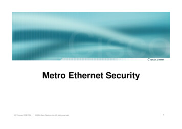
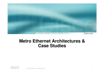
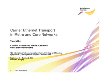
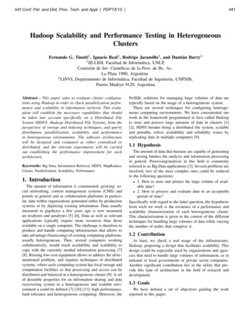
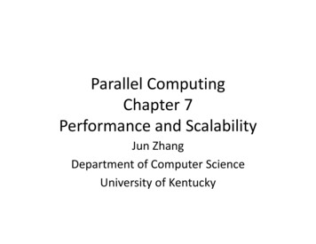
Fig. 3.Fig. 2.Functional elements of metro Ethernet architecture.Metro Ethernet Network reference points.and add-on functions to support Ethernet Service Layer (ETH).Metro Ethernet architecture supports basically any kind ofapplication layer service (TCP/UDP, IP, MPLS, etc.) to becarried in ETH layer. [1]Ethernet Service Layer (ETH) (figure 1) defines Ethernet(MAC address) connectivity service and handles the delivery of ETH frames. ETH layer also handles service awareoperations, administration, maintenance, and provisioning capabilities to support Ethernet type connectivity service. ETHlayer supports broadcast, multicast and unicast Ethernet frameformats defined in IEEE 802.3-2002. [1]Transport Service Layer (TRAN) (figure 1 gives supportfor ETH layer connectivity in a transport mechanism independent manner. Many different transport layer networksand their respective server layers (802.3PHY, 802.1 bridged,SONET/SDH, ATM VC, OTN ODUk, PDH, etc.) can beused to transport ETH layer flows. TRAN layer functionsin between the ETH layer and the physical transmissionmediums. [1]A. MEN Reference PointsMetro Ethernet architecture defines reference points thatmust be used when sending or receiving Ethernet framesacross different network domains. Figure 2 shows a exampleusage of these reference points and how they are used toconnect different parts of a Metro Ethernet architecture.User-Network Interface (UNI) is an interface that connectsMEN service subscribers to MEN service providers networks.UNI is functional element that consist of client (UNI-C) andnetwork (UNI-N) side elements (figure 2). UNI-C supportsfunctionality to exchange data, control and management planeinformation with MEN service provider. The UNI-C is entirely in subscribers domain. UNI-N is entirely in the MENservice providers domain. The UNI-N supports functionalityto exchange data, control, and management plane informationwith the MEN. [1]External Network-to-Network Interface (figure 2) (E-NNI)is used to interconnect two MENs. The E-NNI providesreference point between network equipment inside two MENsthat provide the physical connection between the networks.The E-NNI also defines the protocol exchange that is neededin the interconnected MENs. [1]Internal Network-to-Network Interface (I-NNI) (figure 2)interconnects Network Elements (NE) inside an MEN serviceproviders network. The I-NNI provides reference point fortwo directly connected NEs. The I-NNI provides the protocolexchange that exists between NEs inside the MEN. [1]Network Interworking Network-to-Network Interface (NINNI) (figure 2) is an interface that can be used to support Ethernet service and virtual connections over transport networksnot involved in end-to-end Ethernet service. The NI-NNI isused to preserve the ETH layer frames (as payload) whiletransported over transport networks not directly supportingEthernet transport flows. The NI-NNI defines the protocol exchange needed to connect MENs to other transport networks.[1]Service Interworking Network-to-Network Interface (SINNI) supports interconnection of MENs with other serviceenabling technologies (e.g., Frame Relay, ATM, IP, etc.). TheSI-NNI defines the reference point and protocol exchangebetween MEN and another service network. [1]B. MEN Functional ElementsEthernet Virtual Connection (EVC) (figure 3) associatestwo or more UNIs to each other. The Metro Ethernet architecture supports three types of EVCs. These are point-to-pointEVC, multipoint-to-multipoint EVC, and rooted-multipointEVC. The first of these EVC types can be used to associatenot more than two UNIs between each other, the secondtype supports association between two or more UNIs, and therooted-multipoint EVC is an asymmetric association betweenone or more root UNI(s) and at least one leaf UNI. In therooted-multipoint EVC root UNIs can send ETH frames to anyUNI but the leaf UNIs can only send ETH frames to root UNIs
not to other leaf UNIs. The point-to-point and multipoint-tomultipoint EVCs are symmetric connections and bi-directionalmeaning that UNIs associated with the EVC can send ETHframes to each other. UNI must have at least one EVC to beable to communicate with another UNI. One UNI may havemore than one EVC in it but this demands service multiplexingto be applied in the UNI. [3], [2]Each UNI maps ETH frames into the EVCs with the use ofCustomer Edge VLAN ID (CE-VLAN ID) per EVC map. Inthis map every CE-VLAN ID is mapped to one EVC (UNI cansupport bundling when all or some CE-VLAN IDs are mappedto one EVC).In addition, UNIs must support association ofuntagged frames to an EVC. The CE-VLAN ID value iscarried in the 802.1QTag field that holds 12 bit space forVLAN-ID. Because of the 12 bit restriction only 4095 CEVLAN IDs can be supported at each UNI. [3], [2]The CE-VLAN ID per EVC maps are predetermined andnormally MEN service providers dictate these maps to subscribers UNIs. The Metro Ethernet Forum has not specifieda dynamic way of setting up an EVC with a purpose builtsignaling protocol. However, this is seen as one of the futurework items. [2]APP to ETH Adaptation Function (EAF) (figure 3) isa class of processing entities that provide adaptation of theAPP layer PDUs to ETH layer. EAFs are application (e.g.,IP, voice, video, TDM, etc.). specific entities. The EAF isthe logical interface between the APP and ETH layer. TheEAF consists of source and sink processes. The former isresponsible for LLC PDU formation, EtherType allocation,padding, and multiplexing adapted client PDUs to EFTFfunction. The later is responsible for de-multiplexing clientPDUs from EFTF, EtherType processing and decapsulation,and LLC PDU extraction and forwarding to client processes.[3]ETH Flow Termination Function (EFTF) (figure 3) isa functional entity that creates and terminates ETH network flows. It also functions as a protocol interface betweenAPP and ETH layers. The EFTF consists of source andsink functionality. The source functionality is used for ETHframe preparation (destination and source MAC addresses,802.1QTag, and user data preparation), Formatting of ETHPDUs, and forwarding the PDUs to Ethernet flow domain.The sink functionality is responsible for receiving the ETHPDUs from Ethernet flow domain, extracting the user data,and forwarding the user data to EAF. [3]ETH Flow Conditioning Function (EFCF) (figure 3) isa processing entity that is used for in general conditioning(meaning classification, filtering, metering, marking, shaping,and conditioning) subscriber flows into and out of Ethernetflow domain. The EFCF processing entity consists of ingressand egress functions where the former operates on flows froma MEN and later on flows to a MEN. The egress processingentity includes reception of service frames from subscribersEthernet flow domain, multiplexing of these service framesinto one or more ingress flows, ingress flow conditioningbased on metering, marking, and policing, and forwarding theingress flows to the TAF of the UNI-C. The ingress processingentity is responsible for reception of egress service framesfrom TAF of the UNI-C, egress service frame classificationand conditioning and forwarding the egress service frames tosubscribers Ethernet flow domain. [3]ETH Subscriber Conditioning Function (ESCF) (figure3) is a processing entity responsible for conditioning ofsubscriber flows into and out of service providers Ethernetflow domain. The egress process of the ESCF is responsiblefor reception of ETH frames from the Ethernet flow domainof the service provider and classification of these frames. Inaddition, the egress process is responsible for forwarding theseframes towards the TAF of the UNI-N. The ingress processof the ESCF is responsible of receiving ETH frames fromthe TAF of the UNI-N, classification of these frames, Class-ofService instance determination, ETH frame conditioning, ETHservice frame shaping per resource management requirement,and forwarding egress ETH frames towards the Ethernet flowdomain of service provider (EEAF). [3]ETH Provider Conditioning Function (EPCF) (figure 3)does conditioning of ETH flows between two MENs. Theingress process of EPCF is responsible of receiving ETHframes from TAF of the E-NNI and forwarding these framesto the Ethernet flow domain (EEAF) of the service provider.The ingress process also does classification, CoS instancedetermination, ingress frame conditioning. The egress processof EPCF is responsible for receiving ETH frames from EEAFand forwarding them to the TAF of the E-NNI. The egressprocessing also includes service frame classification and conditioning. [3]ETH EVC Adaptation Function (EEAF) (figure 3) is aprocessing entity that adapts ETH frames into and out ofEVCs. The EEAF is responsible of instantiation of an EVC.The EEAF consists of separate source and sink processes.The source process maps conditioned ETH frames into theirEVC PDUs and forwards the PDUs towards the EVC(s). Thesource process of the EEAF also adapts the subscriber CoSID into service provider CoS, multiplexes ETH frames fromvarious service instances into their corresponding EVC, andbuffer management and scheduling based on the CoS. Thesink process of the EEAF handles the de-multiplexing ETHframes from the EVCs into their service flow instances andforwards these frames to TAF of the UNI or E-NNI (ESCF orEPCF). The sink process also changes the CoS of the serviceprovider back to the CoS information of the subscriber. [3]ETH EVC Termination Function (EETF) (figure 3) createsand terminates EVC trails. To handle EVCs the EETF alsohandles the instantiation of EVCs. The source process ofEETF forwards the adapted PDUs towards the Ethernet flowdomain of the service provider. The sink process receives EVCPDUs from Ethernet flow domain of the service provider andforwards the frames to EEAF. [3]ETH Connection Function (ECF) handles the steering ofEVC PDUs inside the MEN. The ECF switches traffic throughETH links to create point-to-point and multipoint connections.[3]
ETH to TRAN Adaptation Functio
Metro Ethernet Forum (MEF) is responsible of standard-ization a Metro Ethernet architecture that provides carrier grade Ethernet service that can connect two or more distant LANs. Basic Metro Ethernet architecture is built from service providers Metro Ethernet Network (MEN) and two or more subscriber LANs. The MEN consists of Ethernet switches