Transcription
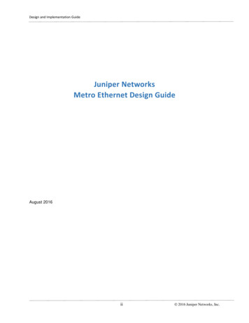
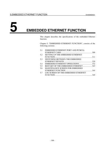
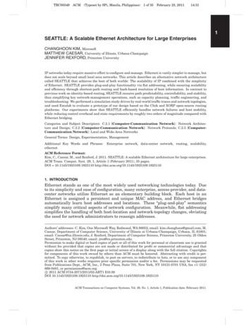
International Journal of Science and Research (IJSR)ISSN (Online): 2319-7064Index Copernicus Value (2013): 6.14 Impact Factor (2015): 6.391Implementation of Ethernet, Aurora and theirIntegrated module for High Speed Serial DataTransmission using Xilinx EDK on Virtex-5 FPGAChaitanya Kumar N.V.N.S1, Mir Mohammed Ali21, 2Mahaveer Institute of Science and Technology, Department of Electronics and Communication Engineering,Hyderabad, Telangana, [at]gmail.comAbstract: This paper implements and establishes serial data transmission techniques like high speed Rocket IO (SERDES/MGT) andGigabit-Ethernet, employing the architectural features of Virtex-5 FPGA. Ethernet and custom Aurora IP core are integrated to theprocessor in EDK (Embedded Development Kit) and the registers which are enabled in the custom Aurora IP core are accessed byEthernet whose assigned data is sent on the Ethernet cable. By using this, the high speed serial data is transmitted at the rate of 1 Gbpsfor Ethernet, 3.125 Gbps for aurora respectively and 1 Gbps for integrated module of Ethernet and Aurora.Keywords: FPGA, Integration of Ethernet and aurora, Aurora Protocol, Multi Gigabit Transceiver, EDK1. IntroductionParallel Data transmission technology has been one of thewidely used techniques for transfer of digital data, in whichparallel lines are used for transmitting and receiving datawhich would consume more resources and time whencompared to serial transmission. So, Serial transmissiontechnology is increasingly used for the transmission ofdigital data due to its improved signal integrity and highspeed.Field Programmable Gate Arrays (FPGAs) are the digital ICsthat are reconfigurable as desired by the designer. That is,any portion of the system can be reconfigured at any timewhile the rest of the design is still working. Xilinx provides alot of tools which will help the designers to configure theFPGAs more quickly and easily. With the advancement ofFPGAs a new trend of implementing the microprocessors onthe FPGAs has emerged in the design community. TheML507 board is such, which supports the embeddedprocessor PowerPC. By configuring the embedded processorit is able to achieve the same transmission and receptionspeeds.This paper describes how the data is transmitted serially athigher speeds using various protocols such as Aurora,Ethernet and the integration of Ethernet and Custom AuroraIP core to the processor so that the processor can access boththe modules simultaneously and interconnects both Ethernetand Aurora to access each other.2. Aurora ModuleWhen transmitting and receiving data serially at higherspeeds, a protocol has to be followed. Here, Aurora protocolis being utilized which is a physical link layer protocol thatuses high speed serial lanes for transmission and reception.The protocol is open and can be implemented using XILINXFPGA technology which is used in applications requiringsimple, low-cost, high-rate, data channels. It is used to movedata from point to point between devices using one or manytransceivers. Aurora utilizes 8b/10b encoding schemedeveloped by IBM hence called- Aurora 8b/10b protocolwhere 8-bit words are translated into 10-bit symbols.Figure 2.1 Block diagram of aurora moduleThe data transmission and reception in Rocket- IO usesAurora protocol on Multi-Gigabit Transceivers (MGTs). A32-bit data from a Virtex-5 evaluation board is transmitted toother board using Aurora protocol. Multi-GigabitTransceivers present in the FPGA are configured usingAurora protocol and works at the clock rate of 125MHz(MGT clock). Aurora protocol converts the parallel data intoserial data and vice versa (SEDERS). The data from Auroramodule is transmitted serially at the rate of 3.125 Gbpsthrough an OFC cable which is looped back as transmissionmedium for high speed serial data transmission. The receivermodule receives data serially and converts it to parallel form.3. Ethernet ModuleEthernet is the dominant wired connectivity standard. TheXilinx Virtex-5 Ethernet media access controller (EthernetMAC) block provides dedicated Ethernet functionality. TheEthernet MAC block is integrated into the FPGA as a hardblock in Virtex-5 devices and is available in the Xilinxdesign environment as a library primitive, named TEMAC.The primitive contains a pair of 10/100/1000 Mbps EthernetMACs.Volume 5 Issue 7, July 2016www.ijsr.netLicensed Under Creative Commons Attribution CC BYPaper ID: ART20164164
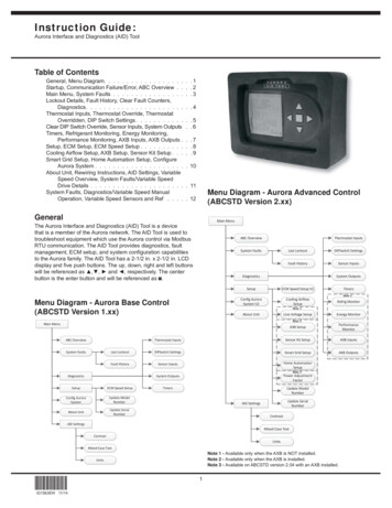
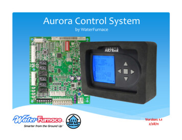
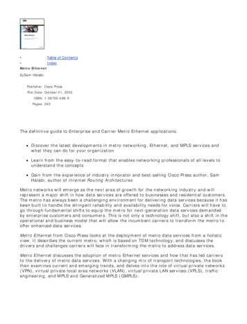
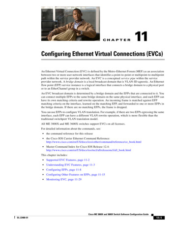
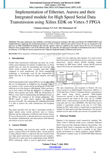
International Journal of Science and Research (IJSR)ISSN (Online): 2319-7064Index Copernicus Value (2013): 6.14 Impact Factor (2015): 6.391Figure 3.1 Virtex-5 FPGA System with the XPS LLTEMAC as the DUTThe block diagram for Ethernet applicaton requires HardEthernet MAC and DDR SDRAM along with PowerPC 440Processor for temporary storage purpose. And otherperipherals to be selected are UARTlite, Block RAM andRS232 with suitable memory storage capacity inorder toexecute the Gigabit Ethernet using Xilinx EDK (EmbeddedDevelopment Kit).4. Integration of Ethernet and Custom AuroraIP coreThe procedure of binding the Ethernet MAC and Auroracore to the Processor is known as Integration of Ethernet andAurora. This makes the processor to control both thecomponents simultaneously and interconnects these twoperipherals with each other so that, both of them can accessone another through the processor. The data present with thecustom IP core can be ported onto the Ethernet MAC and issent on the Ethernet cable to analyze the results. A simpleblock diagram is shown in figure 4.1 to indicate the aboveoperation.Figure 4.2 Exact block diagram of Ethernet and AuroraIntegrationThe precise block diagram of integration is given abovewhich is created in the EDK. This depicts the accurateconnections between all the necessary peripherals likePowerPC-Processor, DDR SDRAM, Hard Ethernet MAC,Custom Aurora IP core, RS232- UARTlite and Block RAM.The yellow line is the Processor Local Bus (PLB) whichconnects the Processor with all other peripherals.5. ImplementationInitially, Aurora and Ethernet are executed individually andthen both are integrated to achieve the desired output. Theimplementation is classified in three sections as follows:5.1 Aurora ImplementationFigure 4.1: Block diagram of Integrated moduleThe process of integration is carried out in two steps.Initially Hard Ethernet MAC is configured with appropriateperipherals and then a custom IP core is created in EDK.After creating the core, it is instantiated according to therequirement and imported into EDK. After executing thetask in EDK, the project is exported to the SDK (SoftwareDevelopment Kit) where the entire hardware portion can beoperated with the help of software.Aurora core is generated in CORE Generator provided byXilinx ISE. The Virtex-5 FPGA board can be configured forspecific device, package and speed grade based on therequirements. The 32-bit data to be transmitted is effective if4 lanes are used out of 16 lanes in the Aurora protocol forthis configured FPGA board.Main Parameters that are required to generate the core areLane up, Channel up, Count signal along with Transmittingdata (Tx D) and Receiving data (Rx D) signals. Once the32-bit data is assigned for transmitting purpose, the samedata flows continuously. A binary counter is designed with32 bit width and it counts up to 32 and overflow occurs asVHDL code is written to generate the required output.Synthesis, simulation and implementation of the code aredone using Xilinx ISim (ISim is an abbreviation for ISEVolume 5 Issue 7, July 2016www.ijsr.netLicensed Under Creative Commons Attribution CC BYPaper ID: ART20164165
International Journal of Science and Research (IJSR)ISSN (Online): 2319-7064Index Copernicus Value (2013): 6.14 Impact Factor (2015): 6.391Simulator, an integrated HDL simulator used to simulateXilinx FPGA and CPLD designs) and chip scope PROanalyzer. Tx D and Rx D signals are loop backed by usingOFC with the help of Small Form factor Pluggabletransceiver (SFP) which is a compact, hot-pluggabletransceiver used for both telecommunication and datacommunications applications.catalog under USER with an ice-cream symbol whichdenotes the custom core as shown in figure 5.2.5.2 Ethernet ImplementationEthernet is configured by enabling the Hard Ethernet MACxps II temac as the main component to the single-processorsystem in the Xilinx EDK. The single-processor systemcontains two types of processors in which one is hardcoreand the other is softcore processor. A hardcore processortype- PowerPC with clock frequency 125.0MHz should beused in synchronous with bus clock frequency of 125.0MHzfor optimal communication as Processor Local Bus (PLB) ispreferred over AXI bus to interconnect the embedded designefficiently. DDR SDRAM for temporary storage purposealong with other peripherals such as UARTlite, Block RAMand RS232 with suitable memory storage capacity areutilized in-order to execute the Gigabit Ethernet using EDK.Figure 5.2: XPS IP catalogAnd now, it is imported to the EDK after adding all therequired files from the Aurora core. The imported peripheralhas to be overwritten by HDL files. Once the importing partis completed, the custom aurora IP is added to the businterface in the highlighted box of figure 5.3.Figure 5.1 Block Diagram of Ethernet ModuleAfter succesful generation of Ethernet Hardware in EDK, theentire project is exported and launched in SoftwareDevelopment Kit (SDK) in order to operate the hardwarewith the help of programming. In SDK, the desired code iswritten in the main.c file of the light weight internet protocoltemplate and the FPGA is programmed.5.3 Integration of Ethernet and Custom Aurora IP coreImplementationInitially for implementing the Integrated module, Ethernetmodule has to be generated as mentioned in the section 5.2.Now, as Hard Ethernet MAC is generated, custom IP corehas to be created to integrate both of them to the processor.To create the custom IP core, a new peripheral is generatedwith XPS project. After generating the necessary files, thecustom IP core named as Aurora will appear in the IPFigure 5.3: XPS wizard with integrated custom IP coreOnce the custom IP has been added, connected with the PLBbus and addresses are assigned, then the entire module isarranged and interconnected as shown in the figure 4.2.Now, as the hardware is ready with both the modulesintegrated to the processor, the project has to be exportedand launched on SDK for further execution. In SDK, thedesired code is written in the main.c file of the light weightVolume 5 Issue 7, July 2016www.ijsr.netLicensed Under Creative Commons Attribution CC BYPaper ID: ART20164166
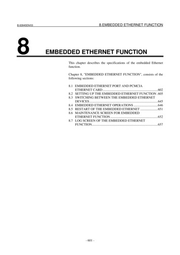
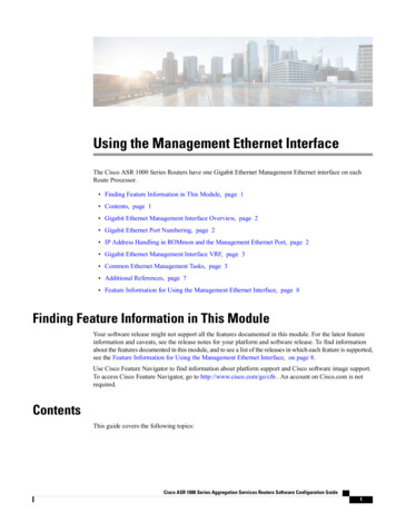
International Journal of Science and Research (IJSR)ISSN (Online): 2319-7064Index Copernicus Value (2013): 6.14 Impact Factor (2015): 6.391internet protocol (lwIP) template which is of standalone andPOSIX thread of xilkernel OS to access both Ethernet andCustom Aurora IP core by the processor simultaneously andstored data in the registers of custom IP core are ported onEthernet.6. ResultsFigure 6.4 IBERT testEthernet, Aurora and Integration of Ethernet and CustomAurora IP core are performed on the FPGA board Virtex-5ML507 and the results are as follows:6.2 Ethernet resultsThe results of the implementation of the Gigabit Ethernetupon launching the hardware, the print results of the lwIPresult of Ethernet module with the Board IP, Netmask,Gateway and link speed and the Xilkernel POSIX threadtemplate can be observed in Hyper Terminal as shown in thebelow figures.Figure 6.1 Virtex-5 ML507 boardFigure 6.5: IwIP result6.1 Aurora resultsThe results of the Aurora module for 32 bit data of 4 laneswith Lane up, Channel up, Tx D, Rx D, count signals areanalyzed in Chipscope Pro which is an analyzer software asshown below:-Figure 6.6 Xilkernel resultThe Ethernet Ping is executed in Command Prompt byentering the FPGA board IP. The number of packets sent,received and lost along with loss percentage are displayed.Figure 6.2 Chipscope-Pro waveform of Tx D, Rx D.Figure 6.7 Ethernet Ping result6.3 Integrated ResultsFigure 6.3 Listing WaveformThe verification of the speed which is 3.125 Gbps is done byIBERT core generator.Hard Ethernet MAC and custom Aurora IP core areintegrated to the single processor on FPGA in EDK and theregisters which are enabled in the custom Aurora IP core areVolume 5 Issue 7, July 2016www.ijsr.netLicensed Under Creative Commons Attribution CC BYPaper ID: ART20164167
International Journal of Science and Research (IJSR)ISSN (Online): 2319-7064Index Copernicus Value (2013): 6.14 Impact Factor (2015): 6.391accessed by Ethernet whose assigned data is sent on theEthernet cable and the results are analyzed.The register reg0 at an address 0xCFC00000 is assignedwith data 0x12. Another register reg5 which is at an address0xCFC00014 is configured in the code to access the datapresent in the reg0 with an incrimination 1 and stored as0x13. Below are the prints of the integrated applicationwhich is executed by taking the data from IP core andporting it onto the Ethernet cable.Figure 6.10: Combined result of Xilkernel and IwIP inHyper TerminalFigure 6.8: Registers output with IwIP in Hyper TerminalThe Ethernet and Aurora Integration continuous Ping isexecuted in Command Prompt by entering the FPGA boardIP with –t.The Ethernet and Aurora Integration Ping is executed inCommand Prompt by entering the FPGA board IP. Thenumber of packets sent, received and lost along with losspercentage are displayed.Figure 6.11: Continuous Ping result of Integrated module incmd7. Conclusion and Future ImprovementsFigure 6.9: Ping result of Integrated module in cmdThe combined result of both Xilkernel and Standalone OStemplates which are Xilkernel POSIX thread template andlwIP templates are modified and below are the prints inHyper Terminal.Hard Ethernet MAC and custom Aurora IP core which areintegrated to FPGA and the data given to the registers whichare enabled in the custom Aurora IP core are sent on theEthernet cable. Another module of the project involvesimplementation of Aurora protocol targeted to virtex-5FX70T FPGA to achieve the above mentioned line rates.The MGT functionality is checked using IBERT tool. All theresults are analyzed, Aurora on Chipscope-pro whereas,Ethernet and Integrated results on Hyper terminal.Volume 5 Issue 7, July 2016www.ijsr.netLicensed Under Creative Commons Attribution CC BYPaper ID: ART20164168
International Journal of Science and Research (IJSR)ISSN (Online): 2319-7064Index Copernicus Value (2013): 6.14 Impact Factor (2015): 6.391The hardware utilization of FPGA for Ethernet and AuroraIntegration are analyzed with design summary in the EDK asin figure 7.1.[5] “EDK Concepts, Tools, and Techniques user guide”,Xilinx, San Jose, CA.[6] “Virtex-5 FPGA Embedded Tri-Mode Ethernet MACUser Guide” (v1.10), Xilinx, San Jose, CA.[7] “Chip-scope pro integrated bit error ratio test (IBERT)for virtex-5 FPGA GTX” (v2.01a), DS774, Xilinx, SanJose, CA, October, 2011.[8] “Aurora 8b/10b protocol specification”, 2010 on/ip documentation Aurora 8b10b protocol spec sp002.pdf.Author ProfileChaitanya Kumar N.V.N.S completed B.Tech inElectronics and Communication Engineering fromMahaveer Institute of Science and Technology,Hyderabad in June 2016. His current area of interest ison FPGAs.Mir Mohammed Ali completed B.Tech in Electronicsand Communication Engineering from MahaveerInstitute of Science and Technology, Hyderabad inJune 2016. His current area of interest is on FPGAsand IoTs.Figure 7.1: Device utilizationWith the help of BSD programming, threads can be createdto access the packets at TCP/IP level for both server andclient where the sent and received packets output could beseen on wireshark. Audio and Video files can be played.This project used independent aurora link on one GTXDUAL TILE for serial data transmission at the rate of3.125Gbps using aurora protocol. The speed upto 17Gpbscan be achieved with some other Virtex series boards whichsupport higher line rates using aurora protocol. Much higherdata rate can be achieved if all of the 16available RocketI/OS are used.References[1] “High speed serial I/O made simple- A designer‟s guidewith FPGA applications”, 1st ed.,Xilinx, San Jose,CA,2005.[2] Volnei A. Pedroni ,“Circuit Design with VHDL”,Cambridge, MA: MIT Press, 2005.[3] Clive „Max‟ Maxfield, “The Design Warrior Guide toFPGA”,MA, 2004.[4] “Virtex-5 special edition”,Xcell Journal, Issue 59, ,Xilinx, San Jose, CA, 2006.Volume 5 Issue 7, July 2016www.ijsr.netLicensed Under Creative Commons Attribution CC BYPaper ID: ART20164169
Ethernet whose assigned data is sent on the Ethernet cable. By using this, the high speed serial data is transmitted at the rate of 1 Gbps for Ethernet, 3.125 Gbps for aurora respectively and 1 Gbps integrated module of Ethernet and Aurora. for Keywords: FPGA, Integration of Ethernet and aur