Transcription
TNC-Pi9K6 9600/1200 BaudAssembly Instructions & OperatingTipsAugust 28, 2018John Hansen W2FSCoastal ChipWorksSpecial Thanks to: John Wiseman, G8BPQMark Griffith, KD0QYNEd Slingland, N2WDEmail: john@hansen.netWebsite: http://tnc-x.com/TNCPi9K.htmTNC-Pi9K6 User Guide-1-1/5/2020
ContentsIntroduction . 3Assembly Instructions. 3Parts List . 3Assembly . 5Schematic Diagram . 8Parts Layout . 9Connecting the Radio. 10Configuring the Raspberry Pi. 11Configuring the TNC . 11Reprogramming the Teensy's Firmware 13Support . 15TNC-Pi9K6 User Guide-2-1/5/2020
IntroductionCongratulations on your purchase of TNC-Pi9K. This board will allow you totransmit and receive either 1200 baud or 9600 baud packet radio transmissionswhen mounted on a Raspberry Pi. This manual is very much a work in progress andsubstantial additions and changes will occur. At this point, the manual is designedto guide you through the assembly process only.Assembly InstructionsParts ListYour kit should come with the parts listed in the table below. You can use the twocolumns of checkboxes to track your progress. As you inventory your parts, put acheckmark in the first column. Once you’ve installed a part, put a checkmark in thesecond column.Notes C1100 µf electrolyticPolarizedC20.1 µf monocapC5Install jumper wire,not capacitor C81 uf cap (blue)***See Note BelowR1, R1547K resistorYellow, Purple, Orange R4, R5, R6, R12, R13620 ohm resistorBlue, Red, BrownR2, R3, R1010K resistorBrown, Black, C-Pi9K6 User Guide-3-1/5/2020
D13mm Red LEDPolarized. Short leadtoward R3. D23mm Yellow LEDPolarized. Short leadtoward D3. D33mm Green LEDPolarized. Short leadtoward D4. D43mm Green LEDPolarized. Short leadtoward D5. D53mm Green LEDPolarized. Short leadtoward corner ofboard. Q1PN2222 transistor3 pin, flat side U1MCP 426114 pin IC with socket.Notch toward Q1 U2MCP602 Op Amp8 pin IC with socketNotch toward U1. JP13-pin headerWith shorting jumper 6 Pin MiniDin JackClip off extra pins onside of part. 9 Pin D-Sub Jack 40 Pin Header U3TNC-Pi9K6 User GuideInstall with pinsupward through theboard. Leave a smallspace between theboard and the headerTeensy Board version3.2-4-1/5/2020
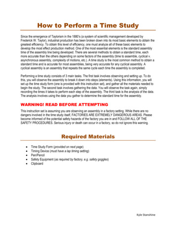
Printed Circuit BoardSpacer and ScrewsFor providing supportfor TNC-Pi9K board onRaspberry Pi.***Most radios do not require C8 and for those you can simply install a wirejumper here (like C5). However occasionally radios have receive audio that isDC coupled (no capacitor in series with the audio output). For those, youshould install this capacitor. So far the only radio that has been reported tohave this issue is a Kenwood TS-V71.Assembly First install all of the parts that lie flat on the board. Note that all of thecomponents are installed on the silkscreen side of the board. Installa. Capacitor C2.b. A jumper wire (you can use the clipped leads from C2) at C5 and C8.c. All of the resistors. Next install the IC sockets. The notches on the sockets should go towardthe left. The notch on the circuit board for U1 is hard to see. It is on theside towards Q1.Do not plug the chips into the sockets at this point. Install the LEDs. The short leads on the green and yellow LEDs should go tothe left, while the short lead on the red LED should go to the right. Install the transistor, making sure that the flat side of the transistor lines upwith the flat side of the part outline on the board. Install capacitor C1. It is polarized. Make certain that the stripe on the sideof the capacitor goes in the hole that is closest to the 8 pin IC socket. Install jumper JP1. This jumper determines which pin on the mini-DINconnector is receive audio. It is different for 9600 baud than it is for 1200baud. Place the included jumper on the side closest to the edge of the boardfor 9600 and the side further away for 1200 baud. Below is a shot of theboard as it will look at this point.TNC-Pi9K6 User Guide-5-1/5/2020
Install the Teensy board at U3. The board should be installed so that theUSB connector is farthest away from JP1. You can clip the pins after youhave completed soldering but be careful doing this because they will have atendency to fly quite a ways when they are clipped. Install the mini-Din jack. Before you do this you will have to clip off the twometal fins on the outside edges of the jack. There are no holes on the boardfor them to go into. Now install the 9 pin D-Sub connector. Ensure that you push it all the wayin so that it is flush against the board. In addition to soldering the pins,you’ll gain mechanical stability by soldering the pins that go into the largeround holes on the sides of the connector. Solder in the 2 x 40 pinheader. It is the only part that is installed throughthe bottom of the board.a. Start by installing this jumper on your Raspberry Pi and thenb. Lower the TNC-Pi9K6 board onto the connector so that the body of theconnector is on the BOTTOM of the TNC-Pi9K6 board.c. Now you’ll need to solder the board so it is about a half millimeter fromall the way down to the base of the connector in order to prevent theboard from bumping into the USB connector on the Pi. It is notnecessary to solder all of the pins. You should at least solder the 4 pinsin the corners (for stability) and the first six pins on each row (pins 1 –12).TNC-Pi9K6 User Guide-6-1/5/2020
Your best bet is to carefully trim the solder leads on the part of the TNCPi9K6 board that will be on the mini-Din connector side of the Pi to get asmuch clearance as possible. You might also want to put a piece of insulatingtape on top of the Pi’s USB connector just to be on the safe side.The pins on the 40 pin header will allow you to stack a second TNC-Pi9K6 ontop of the first one if you choose to do so. Install the ICs in their sockets making sure that the notch on the IC matchesthe notch on the socket. The notches on the ICs should be on the left sideof each of the chips. I’ve included 2 4-40 screws and a 21/32” spacer. You can use this toprovide some additional mechanical stability by putting it between the holein the Pi and the hole in the TNC-Pi9K. Use one of the mounting holes nearthe row of diodes for this purpose. If you are stacking 2 or more TNC’s youmight also find it preferable to use a spacer that is a male to female, ratherthan female to female. These male to female spacers are available on theTNC-Pi9K6 website.Congratulations, you’re done assembling the TNC-Pi9k.TNC-Pi9K6 User Guide-7-1/5/2020
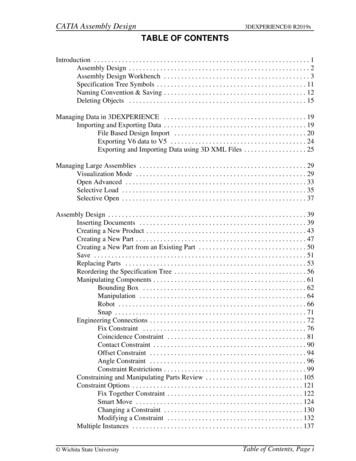
Schematic Diagram (for TNC-Pi9K)(see next page for parts layout diagram)TNC-Pi9K6 User Guide-8-1/5/2020
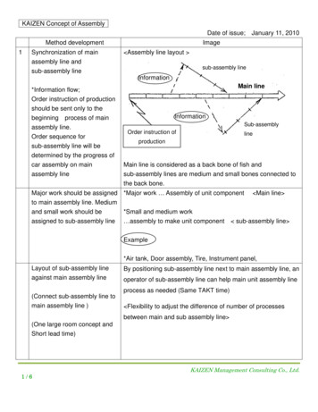
Parts Layout (for TNC-Pi9K6)TNC-Pi9K6 User Guide-9-1/5/2020
Connecting the RadioThere are 3 ways to connect the radio to the TNC: You can use the mini-DINconnector, the 9 Pin D-Sub connector, or connect directly to the four holes that arejust below jumper JP1. The mini-Din connector is perfect for the many transceiversthat have a 6 pin packet connector. This includes nearly all radios that support a9600 baud connection. In that case, you just need to get a 6 pin mini-Din to 6 pinmini-Din cable with plugs on both ends. These are widely available and aresometimes referred to as PS/2 cables. Supplies include Newegg and Amazon or youcan order one from the Coastal ChipWorks website. Be careful when choosing oneof these cables. They were generally used for mouse or keyboard connections insome cases not all six connections were wired (because mice and keyboards didn’tneed all of them). Make sure you get one that has all six connections wired.The 6 pin mini-DIN packet radio connector had a separate connection for 1200 baudpacket receive and 9600 baud packet receive. JP1 is used to select which of thesewires the TNC is connected to. Place the jumper near the edge of the board for9600 baud and near the center of the board for 1200 baud.A second way to connect the TNC to your radio is to use the 9 pin D-Sub connector.The wiring here is the same as for Kantronics TNC’s. It is as follows:PinPinPinPin1 (the square pad): TX Audio3: Push to Talk (PTT)5: Receive Audio6: GroundThe third way to connect the TNC to your radio is using the four holes that arebelow JP1. If you choose this method configure them as follows:PinPinPinPin1:2:3:4:(the square pad): Transmit AudioGroundPush to Talk (PTT)Receive AudioPlease note that you cannot use just any radio to transmit data at 9600 baud.Unlike 1200 baud packet, at 9600 baud data is NOT transmitted by sending tonesover the air. A 9600 baud signal requires that receive audio be connected directlyto the radio’s discriminator. This will require that you either purchase a radio that isdesigned this way, or you modify your radio to make this connection. Modificationof radio’s that are not designed to support this connection is beyond the scope ofthis manual.TNC-Pi9K6 User Guide-10-1/5/2020
Many radios use an industry standard connector (6 pin mini-Din) with standard pinouts to make this connection. These radios include the Kenwood TM-71A and TMD710, the Yaesu FT-7900, FT-817, FT-857. Unfortunately, most manufacturershave only added this feature to their higher end radios. This was not always thecase. I have a Yaesu FT-1500 2-meter radio that I bought some years ago for 125new that works great at 9600 baud. While I have not tested it, the Alinco DR-135( 160) appears to support 9600, but with a non-standard connector.Configuring the Raspberry Pi(NOTE: If you are using Mark Griffith’s PiGate Software SD image, ignore thissection entirely).The following instructions were based on a downloaded image of the “Stretch”version of the operating system. I did this by downloading Raspbian, not NOOBs.It might be a good idea to make sure your Pi operating system is up to date. Youcan do this from the command line by entering the following (this assumes youhave either hard wired or wireless network connectivity):sudo apt-get updatesudo apt-get upgradeWith previous version of the operating system, it was necessary to edit some of theconfiguration files in order to get the serial part to work. With the Stretch version ofRaspian, this is no longer necessary. Go to the command prompt (by clicking on theblack screen icon at the top of the GUI desktop. Run the following: sudo raspi-configA menu will come up. Scroll down to item 5 using the arrow keys and select:"Interfacing Options" Scroll down to item P6 Serial and select that. It will ask you ifyou want to be able to get a log in shell via the serial port. Say No. It will ask you ifyou want the serial port enabled. Say Yes. You'll go back to the main menu. Tabover to and you'll have the opportunity to reboot. Do that, and you are done. Thereare no files to edit. Nothing! Ok, there is one catch. When you address the serialport you have to do it as /dev/serial0. Using the older version of the operatingsystem it was called /dev/ttyAMA0. Note that these configuration instructions workwith any version of the Pi.Configuring the TNCMount the TNC-Pi9K6 on your Raspberry Pi and apply power. If all is well you shouldsee all of the LEDs on the board flash on except for the red PTT LED. Also, placeTNC-Pi9K6 User Guide-11-1/5/2020
your finger lightly on the Teensy board and make sure it does not get really hot. Ifit does, remove power immediately and debug the problem. As shipped, the TNCPi9K6 is set for 9600 baud over the air data transmission/reception. You canchange this, and other parameters using the pitnc getparams and pitnc setparamsprograms. The programs can be downloaded in a .zip file at:http://www.tnc-x.com/pitnc9K6params.zipYou may need to change the permissions on these files in order be able to accessthem. Use chmod to do this. To view the menu of parameters use thepitnc getparams program:./pitnc getparams /dev/serial0 0(if you are in the same directory as the program.) The baud rate is set usingparameter 8. To change it to 1200 baud use the pitnc setparams program:./pitnc setparams /dev/serial0 0 8 12To change it back to 9600 baud:./pitnc setparams /dev/serial0 0 8 96To make these changes effective you need to reboot the TNC. You can do thiswithout removing power with the following command:./pitnc setparams /dev/serial0 0 15 2If you have a radio that has one of the 6 pin mini-Din jacks on it the receive audioat 1200 baud is sent out a different pin on the jack than is receive audio at 9600baud. So if you change the baud rate you must do two things. First change thebaud rate setting in the menu on your radio to the proper baud rate. Second,change the jumper JP1 so that is is set for the proper baud rate. If 1200 baud, setit toward the center of the board; it 9600 set it toward the outer edge of the board.The pitnc setparams program also allows you to set the RX and TX level on theTNC. The optimal RX level at 9600 baud is almost always 0. This value allows theTNC to set it’s own RX level. The RX level is set with parameter 9. We generallyfind that an RX level of 50 is best for most radios when using 1200 baud. Here is alist of some actual voltages for both RX and TX for various parameter values:RX/TX levels and line voltage:-----------------------------255 3000mV P-PTNC-Pi9K6 User Guide-12-1/5/2020
192 2250mV P-P160 2000mV P-P128 1500mV P-P64 750mV P-P32 375mV P-P16 188mV P-P8 94mV P-P4 47mV P-P2 24mV P-P0 0mV (auto-set level for RX only)When I first ran the TNC at 9600 baud, I did so without changing either the TX orRX level. At that point the RX level was set to 0 and the TX level was set to 255. Iwas rather surprised to find that the TNC worked well with these values. It is likelythat the optimal TX level is going to be somewhat lower than this however. The TXlevel is set using parameter 10:./pitnc setparams /dev/serial0 0 10 Xwhere X is the designed value. I have noticed that some radio’s manuals (my FT817, for example) have a recommended voltage level for signals to be transmittedat 9600 bps. My FT-817 suggests a level of 1.0 volts P-P maximum. That wouldcorresponding to a value of 96 for parameter 10. This might be a good startingpoint.Do not change the I2C address value unless you are sure you know what you aredoing. It should remain at 0 for serial port operation. If you set it to somethingelse, it means you are going to communicate via the I2C bus and when you do thisyou will no longer be able to access via the serial port.Reprogramming the Teeny’s FirmwareIn order to switch between the packet firmware and the ARDOP firmware, you willneed to reprogram the Teensy board. Fortunately, this is not very difficult. You willneed a USB cable with a micro USB connector on one end and a standard PC USBconnector on the other end. This is the type of cable that comes with many cellphones (at least until type C USB connectors became common). However, not all ofthese cables will work. Some cables of this type only have wires that deliver powerto the device, they don’t actually transmit data. You will need a cable thattransmits data as well. You will know you have the wrong cable if the Teensy won’tprogram. This is what happened to me when I tried the first cable of this type Icould get my hands on. I swapped this out for a different cable and that time itworked fine.TNC-Pi9K6 User Guide-13-1/5/2020
You will need to download two pieces of software in order to reprogram yourTeensy. First, you need the Arduino IDE. You can find this at the following site:https://www.arduino.cc/en/Main/Software?Do not download the Windows app that appears on this page. Insteaddownload either:Windows Installer, for Windows XP and upORWindows ZIP file for non admin installIf you are using Linux or Mac OS X there is a version of this that you can downloadinstead.Download one or the other of these files and install them as you could any otherprogram.Then you will need the Teensyduino add on to allow the IDE that you justdownloaded to work with the Teensy. You can do this here:https://www.pjrc.com/teensy/td download.htmlThis page contains links to the software and also has instructions on how to installit.Next, download the TeensyProjects.zip file from p this file and you will find the TeensyProjects folder. Move this folder so it iscontained within your Arduino folder. If you accepted the defaults on installation,with Windows 10 it will be within your Documents folder.Inside the TeensyProjects folder you will find the following two files:boards.txtplatform.txtMove these files to the avr folder that is in your Arduino program directory. If youdidn’t change the defaults and you installed this in Windows that will be in:Program Files (x86)/Arduino/hardware/Arduino/avrTNC-Pi9K6 User Guide-14-1/5/2020
Now you can run the Arduino IDE program. Click on File/Preferences on the menu.This will open the Preferences dialog box and the first item will be “SketchbookLocation”. Set this to the location where your TeensyProjects folder is. Forexample, mine Press OK to close the box. Now go to the Tools Menu and change the Board item to“Teensy 3.6”.Go to File/Open and pick the .ino file you want to load into the Teensy. Forexample if you are loading the 1200/2400/9600 baud packet code, click on the SMTeensy directory and select SM Teensy.ino. If you are loading the ARDOP code goto the ARDOP Teensy folder and select ARDOP Teensy.inoPlug your TNCPi9K6 board into a USB port on your computer using the cabledescribed above. You should see lights flash on your TNCPi9K6 board. Then selectfrom the Arduino IDE menu the Sketch item and select Verify/Compile. It will takea while for the firmware to compile, but then another small program will appear onyour screen with directions for programming your Teensy. All you have to do ispush the white button on the Teensy board. This is where you will find out if youhave the right cable or not. If you see the progress bar indicating that the Teensyis programming you have the correct cable.SupportIf you have any questions about your TNC-Pi9K6 or are having hardware issues withit, please contact John Hansen, W2FS at john@coastalchip.com. Software issues,particularly with regard to the Linux version of BPQ are best addressed to theauthor, John Wiseman, G8BPQ.There is a support group for the Raspberry Pi uses in amateur radio that focusesmainly on using TNC’s with the Pi. You can find it on groups.io:https://groups.io/search?q RaspberryPi-4-HamRadioTNC-Pi9K6 User Guide-15-1/5/2020
TNC-Pi9K6 User Guide -3- 1/5/2020 Introduction Congratulations on your purchase of TNC-Pi9K. This board will allow you to transmit and receive either 1200 baud or 9600 baud packet radio transmissions when mounted on a Raspberry Pi. This manual is very much a work in p