Transcription
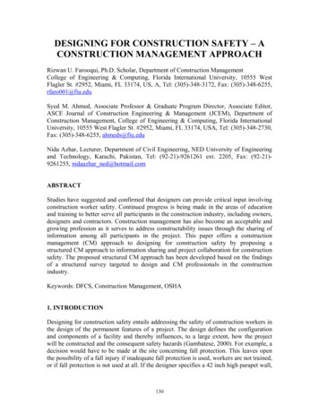
CONSTRUCTION PLANS FOR 10 TNC(PART ONE)Gordon L. Gibby KX4ZOctober 3 2016NOV 16 NOTE: This construction project is a work in progress --- so the inexperienced reader isadvised to read through both this document and the companion “Part Two” to decide exactly whichoutput circuitry and where to position them. A beginning builder may prefer to use the two-boardsolution exhibited in “Part Two”.To make a packet TNC, or to send PSK31 or any of several popular digital-over-audio modes, all youneed is a sound card that generates the audio tones, a volume control to match those to the transceivermic input; a volume control to match the transceiver audio output to the sound card mic input, and away to activate the push-to-talk circuity fast enough to follow the ARQ handshaking of modes likepacket. Add free software such as UZ7HO soundmodem.exe, or FLDIG, and start having digital fun!This is a simple push-to-talk vox-type circuit that combines with an Adafruit Audio Adapter to make acomplete sound-card-based TNC using freely available software. This circuit approximates thefunctions of the vox circuitry within the very popular Signalink-USB. The circuit is not original with1
me; I found the idea on a British ham's web page. It can be built compact enough to fit into an Altoidtin -- or the entire thing including the Adafruit Audio Adapter can bit within a tea tin; or even easier,taped to the insides of a small cardboard box (e.g., granola bars box) and covered with aluminum foil.MaterialsAdafruit Audio Adapter ( 5 from Adafruit, more expensive from id Cj0KEQjwg8i BRCT9dHt5ZSGi90BEiQAItdjpJNq5fA6CG03Ky7dnef3tH QqTrcHCX21SXpH8PFisaAu1u8P8HAQProtyping Printed Circuit BoardSmall board -- BY-MCM-21113-/21-4590Resistors -- 1/4 or 1/2 watt (not wirewound)R1 -- Not used in my prototype, but I had to turn the TX GAIN almost down to the bottomand the adjustment was tricky. Suggest using a 4.7 - 10K /597199500 ohm potentiometer, R2, R6 nc/3306K1-501/3306K-501-ND/8479147K, R3 1220K R4, R8 (red, red, yellow) 210K, R7, R9, R11 (brown, black, orange) K (4700 ohms) (yellow, purple, red) R5 200JR-52-4K7/4.7KZCT-ND/2059014CapacitorsCeramic 0.01 microfarads (10,000 pf) C1,C2, C5, C8, C9. Ceramic, any voltage 25 or /490-11884-ND/4277785Ceramic 0.1 microfarad C7. trolytic (polarity important) 1 microfarad C3, C6, any voltage 15 volts47 microfarads, C4, any voltage 15 volts https://www.digikey.com/product2
470/P5539-ND/245138TransistorsAll transistors can be 2N3904 or almost any general purpose NPN transistor, including the2N2222. Note you must idenfify which lead is the emitter, base and collector. In the drawingsof the schematic, the emitter is the one with the arrow, and goes to ground. The Collector is thehighest terminal. The base is the lead that goes to the LEFT. Different transistors can havetheir leads placed differently on their 4 pinout: odesD1,D2 can be any kind of diode, including small signal diodes. The BAND on the physicaldiode corresponds to the vertical thin line side. A 1N4148 or 1N4448 will rchild-semiconductor/1N4448TR/1N4448CTND/458915 http://www.vishay.com/docs/81857/1n4148.pdf However, it is ABSOLUTELYNON CRITICAL. Any of the 1N400X series (1N4001, 4002, 4003, 4004, 4007) will alsowork.D3: This diode shorts out the reverse voltage that an inductor creates when the current israpidly stopped (when the PTT circuitry stops pushing to talk) -- I would use one of the1N400X series for this diode. sL1,L2,L3: Approximately 0.5 microhenries, easily made by wrapping about 8-10 turns of solidhookup wire around a pencil or phillips screwdriver and then removing the pencil orscrewdriver and the inductor should keep its form. If you are planning to use this for HF,, youmight consider using a toroid with 6 turns or so. The purpose of this is to create impedance tostop incoming radio frequency interference.Relay (optional)--but highly recommended as the relay output has had far less trouble with RFIproblems than the open collector versionRL1 5volt, reed relay, low current draw ( 20 mA) e.g. nology/9007-05-00/306-1062-ND/301696 (10mA coil current)Ferrite Core for transceiver cable:Example: 802LED (indicator) D/8271113
Tools small needle nosed plierssmall diagonal cutter (“dikes”)low-wattage soldering iron (e.g., 25-40 watts) Here's an example from 71B30KT-30W-Soldering-Iron-PenKit/49016054 for under 10. It is almost impossible to build this circuit with a big solderinggun -- a nice pencil point gets into tight spaces and doesn't create “solder bridges”something safe to set the hot iron on, that will cradle it to some extent. metal, ceramic or brick.I use good sized electric junction box.rosin core (electrical) solder, lead alloy preferred (lower melting temperature). You won't needa lot. I prefer the 60/40 lead tin (lowest melting point) but it is getting harder. It is a lot easierto build small circuits if you have THIN (small diameter) solderOptional: alligator clip parts holding “third hand”Optional: magnifying glassVoltmeter ( 5 Harbor freight digital multimeter works fine)You may want to have a “solder sucker” or “solder wick” to absorb mis-placed solder thatcreates an unwanted solder bridge.CONSTRUCTIONThe circuit consists first, of a circuit that turns the transmitted audio into an ON-OFF dc voltage that isused to drive any of several optional output circuits:- An open collector transistor switch that can short to ground a positive voltage from a transceiver pushto talk circuit of up to about 20 mA (more prone to RFI however, if there is any RF around yourstation.)- An optional LED indicator that will light up during transmit (helpful if you are having problems withcircuitry or RFI).- An optional relay output that can drive higher current push to talk, provide more isolation of thecircuitry to reduce RFI problems, or switch a negative voltage, should your transceiver's push to talk benegative (most aren't).You can use any or all of the output circuits.The audio signal from the USB audio device is a low voltage audio signal, less than 1 volt. Q1 is asimple transistor amplifier that develops roughly a 4 volt peak-to-peak AC signal from the low voltageaudio input signal. Diodes D1 and D2 rectify this to create a positive DC voltage. C7 provides a verysmall delay to keep the transmitter ON. The turn-off delay constant of this circuit is at a minimum theresult of 0.1 microfarads and 3.3kohms (if all three output circuits are built) or 0.3 milliseconds, butprobably 2 time constants have to expire before the PTT stops. This is long enough to keep the push totalk energized throughout the audio signals.4
Building the PTT input circuit.There are multiple building techniques, even including “dead bug” construction in mid-air. Most smallcircuits are more easily built on perforated board which provides mechanical support. Using perfboard with copper lands (“printed circuit board”) makes it even easier because connections can bemade by using lands that connect multiple holes.Most simple circuits that are not at radio frequency, can be built by laying out the componentssomewhat as they appear on the schematic. I generally prefer to write schematics and build circuitsfrom left to right.The board chosen for this project has two “bus bars” running across the board, however these are reallyCLOSE to each other to use one as the plus voltage and one as the negative.too close for possiblesoldering errors. So I use one of them as the positive bus bar and run a bit of hook up wire along theperiphery of the board (both top and bottom) as the “ground”. Although I put it on the componentside, I think it would actually be better to put the ground bus on theprinted side. Either can be done.In this case, I build the input circuit on the “bottom” of the board, and then rotate the board 180 degreesand build one nor more output circuits on the “top” of the board.The photo above shows the completed “input” circuitry, all the way to the development of the filteredDC voltage.I over-crowded the input portion of the circuit, R2, C1, C3. That made it hard to fit in L1 and C2 lateron. Give yourself just a little more room and move R2 a couple of holes further to the right on theboard.NOTE: FOR BEGINNING CIRCUIT BUILDERS, IT IS PROBABLY A BETTER IDEA NOTTO PLACE THE TRIMMER POTENTIOMETER HERE AT ALL, BUT INSTEAD TO BUILDIT ON A SEPARATE BOARD. THAT ALLOWS THIS BOARD TO HANDLE ONLY PUSH TOTALK, AND A SECOND, SMALLER BOARD TO HANDLE THE AUDIO INPUT/OUTPUT.SEE THE COMPANION DOCUMENT (“PART TWO”) FOR MORE DETAILS.COMPONENT LAYOUT: The photo below shows the component names:5
Leave a bit of room to get at the wiper (center pin) of R2 as you'll have to connect to it later.Be sure to get the polarity of C3 and C6 -- the plus side is closest to Q1, and the negative side away.You can see that I put C4 and C5 to the far right side of the board. These are easy to install and areprobably the first two components to install to get some practice soldering.6
Building the output circuitsI originally chose only to build the open collector PTT on this model (I did the LED on my previousbuild). Flip the board around and pick a spot on which to work. I started to the far left, which leftplenty of room for the inductors that would be added later.RELAY OUTPUT: In subsequent builds I preferred to build the relay output. It seems more immuneto RFI. You must remember the diode 'backwards” across the relay coil or you may fry the switchingtransistor.The photo below shows the reed relay positioned on the opposite side of the board, the switchingtransistor. A separate transistor drives an LED. If you want a dim LED, put 4.7K in series with it, ifyou want a very bright LED, put 1000 ohms in series with it. The longer lead on the LED goes to the V side.7
Final CompletionI think the open air construction that I used for L1, L2 is easier than the dowel-rod that I used for L3, soI suggest it for all of them, but I would shoot for about 8 turns.Add in the R6 potentiometer for the RX gain control.8
Wiring to the USB audio dongle:There are four signals you need to connect to. Using tiny very flexible stranded wire will make this alot easier. After you get all the connections done and have tested the circuity, I recommend a bit of 5minute epoxy to glue the USB circuit board back into the bottom half of its clamshell, and a dab on thewhite cable coming fromthe computer to strain relief it. V (5V DC) which is on the little red wire coming from the USB. You are probably going tohave to disconnect that tiny wire, connect to it, and then run a short jumper back to the board.This is tiny tiny soldering so be careful.Ground -- easiest picked off of the farthest tab on the audio connectors.Audio output from the computer --- from the channel closest to the computerMic input to the Computer (will go to the speaker output from the transceiver) -- from the tabclosest to the computer.The photo below shows an earlier prototype where the audio potentiometer were mounted right on thejacks in the Adafruit Audio adapter, but it shows you where the terminals are that you need to connectto:9
On both the audio output (top) and mic input (bottom), the farthest right termimal is ground, and thefarthest left terminal is the signal you want. Solder quickly so you don't melt the entire jack and it willwork nicely!Wiring to the Transceiver:There are four signals you will need to connect to the transceiver: Mic inputSpeaker outputPush To Talk controlGroundI recommend using shielded wire to run these signals to the transceiver, with the ground connected tothe shield at the computer/circuitry side. Leave enough room to put a 2.5” loop a couple of times inthis cable to add common mode inductance, and crucially, put a ferrite bead close to the transceiver.In my station, all cables coming from transceivers terminate in a RF45 wired in the way that wouldconnect to a Signalink which has been configured for their Baofeng/Kenwood connector:RJ45 Pin1235SignalMicGroundPush to TalkSpeaker audioI choose to wire the cables from my TNCs (the ones that don't have female jacks accepting10
RJ45 like a Signalink) in the exact same way, and then use a female-female RJ45 compatibleadapter to connect TNC to transceiver. This makes it a lot easier for me to “mix and match”different radios and TNCs when necessary.SOFTWAREI use UZ7HO soundmodem.exe (the 1200 version, not the high speed 9600 baud version) for packet.This wraps the sound card/ptt circuity and gives it both an AGWPE and KISS
CONSTRUCTION PLANS FOR 10 TNC (PART ONE) Gordon L. Gibby KX4Z October 3 2016 NOV 16 NOTE: This construction project is a work in progress --- so the inexperienced reader is advised to read through both this document and the companion “Part Two” to decide exactly which output circuitry and where to position them. A beginning builder may prefer to use the two-board solution exhibited in .