Transcription
Precision Engineering 28 (2004) 218–231Precisely positioning pallets in multi-station assembly systemsR. Ryan Vallance a, , Chris Morgan b,1 , Alexander H. Slocum c,2acDepartment of Mechanical and Aerospace Engineering, The George Washington University,738 Academic Center Bldg., 801 22nd St., N.W., Washington, DC 20052, USAb Department of Mechanical Engineering, University of Kentucky, 015 Ralph G. Anderson Building, Lexington, KY 40506, USADepartment of Mechanical Engineering, Massachusetts Institute of Technology, RM 3-445 77 Massachusetts Ave., Cambridge, MA 02139, USAReceived 28 August 2002; accepted 14 November 2002AbstractIn multi-station assembly systems, common for mass-customization manufacturing strategies, the product being assembled is held in afixture attached to a pallet, and the pallet is conveyed between workstations. In high-precision assembly systems, variation in the position ofthe pallet is one of the largest sources of variation within the error budget, reducing quality and yields. Conventional approaches to locatingpallets use pins and bushings, and a method for predicting their repeatability is presented. This paper also presents an exact constraintapproach using a split-groove kinematic coupling, which reduces variation in pallet location by an order of magnitude. 2003 Elsevier Inc. All rights reserved.Keywords: Kinematic couplings; Split-groove coupling; Pallets; Flexible assembly systems; Assembly automation1. IntroductionNearly all products require that manufactured parts be assembled together into a final product. The assembly processis conducted manually and/or automatically using assemblymachines. The term “assembly automation”, popularizedaround World War II, refers to the mechanized feeding,placement, and fastening of manufactured components into acomplete product assembly. Since tooling and equipment isoften dedicated to a particular product, automated assemblyis generally reserved for mass-produced components, wherethe expense of custom tooling and equipment can be distributed over many units. During the 1970s and 1980s, muchengineering and research effort concentrated on exchanginghard automation for flexible automation by incorporatingre-programmable equipment such as robots and computercontrolled machinery. Flexible automation prolonged the lifeof capital equipment, and consequently, automated assembly became economical for lower-volume production. Morerecently, reduced time-to-market and shortened product lifecycles provided further incentive for flexible automationusing computer-controlled equipment. For these reasons, Correspondingauthor. Tel.: 1-202-994-9830; fax: 1-202-994-0238.E-mail addresses: vallance@gwu.edu (R.R. Vallance),cjmorg1@engr.uky.edu (C. Morgan), slocum@mit.edu (A.H. Slocum).1 Tel.: 1-859-257-6336x80676; fax: 1-859-257-3304.2 Tel.: 1-617-253-0012; fax: 1-617-258-6427.0141-6359/ – see front matter 2003 Elsevier Inc. All rights omated assembly machinery is now commonly used formany products.To achieve economical production, assembly tasks arefrequently executed simultaneously on several product unitsusing multiple machines. This generally requires that the machines or workstations be organized into an assembly system,and the products are then transported between machines ormanual workstations. There are three principal categories ofassembly systems: synchronous, non-synchronous, or continuous assembly systems. Synchronous systems cyclically index the products to individual machines simultaneously withfixed frequency. In non-synchronous systems, the assemblymachines operate independently, and the index time dependsupon the task time at each machine. Non-synchronous systems therefore employ buffers between the machines or stations to accommodate different task times at each station. Incontinuous systems, the product remains in constant motion,and the tasks are performed while the product travels.All three types of assembly systems require that the product be transported through the system. In synchronous andnon-synchronous systems, the product units are stationary ateach assembly machine or workstation. Therefore, the product unit must be statically positioned with respect to each assembly machine. A common approach is to hold each productunit in a fixture attached to an assembly pallet as illustratedin Fig. 1a. Then the pallets can be moved synchronously ornon-synchronously throughout the assembly system using apallet transportation system. Multi-station assembly systems
R.R. Vallance et al. / Precision Engineering 28 (2004) 218–231NomenclatureδxaicdhdpDhDpD siEeEfEs[K]lCDlCElDEradius of contact area at contact point iclearance between pin and holedistance between holesdistance between pinsdiameter of holesdiameter of pinsdiameter of sphere at contact point iequivalent modulus of elasticitymodulus of elasticity for flat surfacemodulus of elasticity for spherical surfacekinematic coupling’s system matrixlength of line CDlength of line CElength of line DEδyLALDvector (6 1) of applied forces and momentsvector (6 1) of disturbance forces andmomentsvector (6 1) of preload forces and momentsvector (6 1) of weight forces and momentsunit normal vector at contact point iposition vector locating ball jposition vector locating contact point iposition vector locating an operating pointafter error motionposition vector locating an operating pointbefore error motionvector (6 1) of contact reaction forceshomogenous transformation matrixrepresenting error motioncoordinate of a point in the x directioncoordinate of point D in the x directionapproximate coordinate of point D in xdirectioncoordinate of point E in x directionapproximate coordinate of point E in xdirectioncoordinate of a point in the y directioncoordinate of point D in the y directionapproximate coordinate of point D in ydirectioncoordinate of point E in y directionapproximate coordinate of point E in ydirection LPLW ni P Bj PC iPE Po RC[TE ]xxDx̂DxEx̂EyyDŷDyEŷEGreek letters δδc δ ci δEtranslation errorvector (6 1) of elastic deformation atcontact pointselastic deformation at contact point ivector (6 1) of error motion translationsand rotationsθθ maxνfνsρσmaxiτmaxi219component of translation error in the xdirectioncomponent of translation error in the ydirectionrange of rotational errormaximum range of rotational errorPoisson’s ratio for flat surfacePoisson’s ratio for spherical surfaceestimate of repeatabilitymaximum tensile stress at contact point imaximum shear stress at contact point ioften use conveyor belts as illustrated in Fig. 1b, and theygenerally operate non-synchronously.This paper presents designs and techniques for preciselypositioning assembly pallets at individual machines withinassembly systems. Two separate approaches, pins-in-holesand exact constraint, are compared on the basis of stiffnessand positional repeatability. It is shown that the repeatabilityof the exact constraint approach is much better than withthe pins-in-holes approach. Although the static stiffnessof the pins-in-holes approach can be greater, the stiffnessof exact constraint is usually sufficient for most assemblytasks. Therefore, in precision assembly systems, the advantage of positional repeatability using exact constraint oftenoutweighs additional improvement in static stiffness.2. Positioning with pins in holesA common technique for positioning one body with respectto another is to mate a set of pins (fixed in one body) insidea set of holes (in the second body). This pins-in-holes (PIH)technique is non-deterministic since contact between the twobodies may or may not occur. If contact occurs, it is difficultto anticipate the locations of contact, quantity, or sizes of anycontact regions. This uncertainty arises from manufacturingerrors in:(1)(2)(3)(4)(5)distances between the pins or holes,diameters of the pins or holes,straightness of the pins or holes,parallelism of the pins or holes, andcylindricity of the pins or holes.Since PIH approaches are non-deterministic, their performance (repeatability and stiffness) is difficult to analyze orpredict a priori, especially if more than two pins and twoholes are used. The relation between design parameters (e.g.diameter of pins, clearance between pins and holes, distancesbetween pins/holes) and performance cannot be expressedanalytically for PIH configurations. As a result, it is oftennecessary to experimentally measure the repeatability andstiffness with actual manufacturing errors. For these reasons,we are limited to estimating planar repeatability for PIH de-
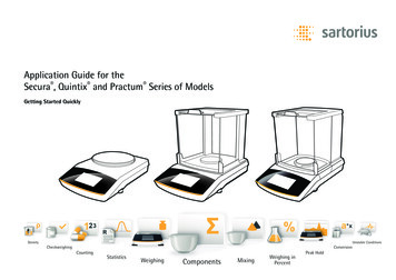
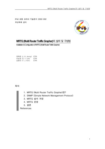
220R.R. Vallance et al. / Precision Engineering 28 (2004) 218–231Fig. 1. (a) Pallet and fixture for holding electrical connector during assembly operations and (b) flexible assembly system with conveyors for non-synchronouslytransporting pallets.signs employing only two pins and two holes (Section 2.2)and a qualitative discussion of static stiffness (Section 2.3).2.1. Design of pins-in-holes positioning techniqueA PIH positioning system may use any quantity of pinsand holes, and as the quantity of pins and holes increases,the precision of the positioning improves and the stiffnessincreases. However, systems with more than two holes andtwo pins require tighter tolerances to prevent binding whilemating the two objects. If the clearance between the pins andholes is insufficient to accommodate manufacturing errorsthen binding occurs, and large forces are necessary to elastically deform the pins and holes. Design precautions, whichdegrade the precision and stiffness, are necessary to reducethe chance of binding due to manufacturing errors.The most obvious and common design precaution is toincrease the clearance between the outer diameter (OD) ofthe pins and the inner diameter (ID) of the holes by manufacturing the holes slightly larger than the pins. This precautionaccommodates many types of manufacturing errors, but dramatically reduces repeatability and stiffness of the PIH design. Another precaution reduces the sensitivity to manufacturing errors in the roundness, straightness, and parallelismby minimizing the length of engagement between the pinand hole. This is frequently accomplished using pins withlarge rounds or bullet noses that lead into shorter cylindricalregions, such as those shown in Fig. 2. A third design n uses one round pin (Fig. 2a) and one diamond shapedpin (Fig. 2b) to reduce the sensitivity to a difference in thedistance between pins and the distance between holes. Thediamond pin is manufactured with two sharp corners and tworounded corners. The rounded corners have approximatelythe radius of an equivalent round pin. The distance betweenthe two sharp corners should be less than the diameter ofan equivalent round pin, and the distance between the tworounded corners is approximately equal to the diameter of anequivalent round pin. The diamond pin is oriented during assembly so that one of the sharp corners points directly towardthe round pin. This insures that the rounded corners pointperpendicular to a line connecting the centers of the two pins.Fig. 3 illustrates an industry standard pallet that uses thePIH positioning technique [1]. In this pallet system, two ofthe design precautions are applied. A round pin is used alongwith a diamond pin, and the tolerances are such that clearanceis guaranteed between the pins and holes. The pallet is constructed of a steel or aluminum plate surrounded with a polyimide frame. Hard bushings with ground bores are pressedinto the plate, and hard pins with ground surfaces are attachedto the machine or assembly station (represented by plate inFig. 3).DiamondShapeRound PinDiamond Pin(a)(b)(c)Fig. 2. Commercially available positioning pins and bushing (a) round pinwith bullet nose, (b) diamond pin with bullet nose, and (c) bushing.MachineBaseFig. 3. Position method in commercial pallets using pins-in-holes approach(distance between pins equals 287.5 mm (11.321 in.)).
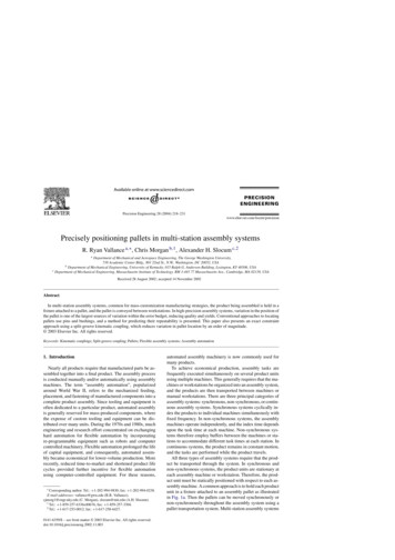
R.R. Vallance et al. / Precision Engineering 28 (2004) 218–231221Table 1Dimensions and tolerance of pins and bushing holes for industry standard palletObjectGeometryNominal diameter dimensionDiameter tolerance specificationand tolerance rangeRound pin12 mm (0.4724 in.)e7 0.0305 mm (0.0012 in.) 0.0483 mm (0.0019 in.)Diamond pin12 mm (0.4724 in.)e7 0.0305 mm (0.0012 in.) 0.0483 mm (0.0019 in.)Round bushing12 mm (0.4724 in.)H7 0.0178 mm (0.0007 in.) 0.0000 mm (0.0000 in.)The geometry, dimensions, and tolerance for the groundpins and bushings for the pallet system illustrated in Fig. 3 aresummarized in Table 1. According to the tolerance specifications, the minimum pin diameter is 11.952 mm (0.4705 in.),and the maximum bushing bore diameter is 12.0178 mm(0.4731 in.). Hence, the worst-case diametric clearance isabout 66 m (0.0026 in.). The manufacturer of the palletsystem illustrated in Fig. 3 specifies that their pallets arerepeatable to within 50 m ( 0.002 in.) [1].2.2. Estimating precision of pins-in-holes positioningThe precision, or two-dimensional repeatability, of a particular PIH design is difficult to predict a priori since thepallet’s position is non-deterministic and depends upon manufacturing errors. However, an estimate of the worst-caselimit on repeatability can be obtained as an envelope thatbounds possible translation and rotational errors. This section presents a technique for determining that envelope forPIH designs that use a bullet-nose round pin, a bullet-nosediamond pin, and two bushings. The clearance is assumedsufficient to prevent binding. The diameter and geometricform of the pins and holes is assumed perfect (roundness andstraightness), and contact is assumed to occur only aroundthe circumference of the pins. The clearance between a pinand hole, c, is defined in Eq. (1) to be the difference betweenthe nominal diameter of the pins, Dp , and nominal diameterof the holes, Dh :c Dh Dpcrosshatched circles represent the pins in the stationary object(machine base or workstation). The errors are measured in areference coordinate system with origin, O, located at the center of Pin 1 with x-axis pointing towards the center of Pin 2.The coupled body (pallet) is shown in two distinct orientations. The two orientations are the extreme cases of rotationalerror, limited when Hole 2 contacts Pin 2. In the first orientation (solid lines with crosshatching), Pin 2 contacts Hole 2 atPoint A, and in the second orientation (dashed lines withoutcrosshatching) Pin 2 contacts Hole 2 at Point B. Both orien tations are illustrated with the same translation error, δ , thathas components δx and δy in the x and y directions of thereference coordinate system located at the center of Pin 1.The potential range of rotational error, θ, depends upon the direction and magnitude of the translation error, δ . Forinstance, a translation error solely in the x direction withmagnitude equal to the clearance will not permit any rotational error, but a translation error solely in the y directionwith magnitude equal to the clearance permits rotationalerror. Therefore, an expression for the range of permissiblerotational error as a function of translation errors is neededto evaluate the potential repeatability errors of a PIH design.(1)Fig. 4 illustrates the errors between two rigid bodies connected with a PIH design using two pins and two holes. Thedistance between the two pins is dp , and the distance between the two holes is dh . The clearance between the pinsand holes is exaggerated for illustrative purpose. Since PIHis a planar positioning technique, we are only concerned witherrors in three degrees of freedom: translation in the x direction, translation in the y direction, and a rotation angle. TwoFig. 4. Errors in pin-in-hole positioning technique.
222R.R. Vallance et al. / Precision Engineering 28 (2004) 218–231The centers of Hole 2 in the two extreme orientations lie atthe intersections of two theoretical circles, labeled as CircleA and Circle B in Fig. 4. The center of Circle A is at the centerof Hole 1 (Point C), and its radius is equal to the distancebetween the two holes, dh . Circle A represents the locus ofpoints traced by the center of Hole 2 when a rotation occursabout Point C. Points that lie on Circle A satisfy Eq. (2):(x δx )2 (y δy )2 dh2c24x̂D x̂E δx dp ŷD c2 δ2x4(2)The center of Circle B is at the center of Pin 2, and its radiusequals the difference between the radii of the hole and pin.The radius of Circle B equals the maximum distance betweenthe center of Pin 2 and Hole 2 that can ever occur. Points thatlie on Circle B satisfy Eq. (3), which is written in terms ofthe diametric clearance, c:(x dp )2 y2 centers of Hole 2 in both orientations are given by Eqs. (9)and (10), respectively:(3)In the two extreme orientations, the center of Hole 2 couldbe located at either Point D or E. The coordinates of PointsD and E in the reference coordinate system can be determined by solving Eqs. (2) and (3) as a system of simultaneousnon-linear equations. The coordinates of Points D and E aredesignated as (xD , yD ) and (xE , yE ), respectively, and can bereadily calculated using iterative techniques. Once the coordinates Points D and E are determined, the lengths of edgesalong triangle CDE can be calculated. The lengths of the triangles edges (lDE , lCD , and lCE ) are given by Eqs. (4)–(6):lDE [(xE xD )2 (yE yD )2 ]1/2(4)lCD [(xD δx )2 (yD δy )2 ]1/2(5)lCE [(xE δx )2 (yE δy )2 ]1/2(6)The potential range of rotational error, θ, equals the anglebetween the edges CD and CE. Since the three edges’ lengthsare known, the angle θ can be calculated using the Law ofCosines as shown in Eq. (7): 2 l2 l2lDECE(7)θ f(δx , δy ) cos 1 CD2lCD lCEAlthough Eqs. (2)–(7) yield a general solution, the analysisfor most PIH systems, including pallet positioning, can beapproximated with a simpler closed-form solution that doesnot require iterative methods. The approximate solution isderived with a few reasonable assumptions. Small clearancesare assumed so that Dh and Dp are approximately equal, andthe distances between the two pins and two holes are assumed to be equal (so that dp equals dh ). The coordinates forPoints D and E approximated with these assumptions is distinguished using above the variables, x̂D , ŷD and x̂E , ŷE .The approximate coordinates in the x-direction, x̂D and x̂E ,are equal; their value is simply the sum of the translation errorin the x direction and the distance between the pins as givenin Eq. (8). The approximate y coordinates, ŷD and ŷE , for the ŷE (8) 1/2c2 δ2x4(9) 1/2(10)For most applications, the distance between the pins is muchc), and therefore, lCD andgreater than the clearance (dplCE are approximately equal the distance between the pins,dp . Substituting the approximate coordinates from Eqs. (8)to (10) and dp for lCD and lCE into Eq. (7) yields a closed-formestimate for the potential range of orientation error, θ̂. Notethat the approximate range of angular error does not dependupon δy : 22c2δθ̂ f(δx ) cos 1 1 2 2x(11)2dpdpFrom Eq. (11), it is evident that the maximum rotational error,θ̂max , occurs when the translation error is zero (δx 0). Accordingly, the approximate maximum rotation error is givenin Eq. (12). This result matches engineering intuition in thatreducing the clearance and increasing the distance betweenpins reduces rotational errors: c2 1θ̂max cos1 2(12)2dpFinally, an envelope bounding the repeatability errors for aparticular PIH design can be specified. Due to the circularperimeter of holes and pins, the translations in both the x and ydirections are limited within a circle of radius c/2; hence, thetranslation errors are bounded by c/2 and c/2. The rotationalerrors are bounded within θ̂max /2 and θ̂max /2.A visual interpretation of these limits to repeatability errorsis obtained by graphically plotting θ max or θ̂max as a functionof δx and δy . The translation errors in the x and y directionsare plotted along the x and y axes, and the range of rotationalerror is plotted along the z-axis. Fig. 5 shows a graph ofthe repeatability limits for the examplary PIH pallet systemshown in Fig. 3 with dp 287.5 and c 0.0661 mm. Therange of rotational errors shown in Fig. 5 was determinedusing the approximate solution method. For this particularPIH pallet system, the maximum range of rotational error iscalculated to be around 2.3 10 4 radians. This rotationalerror is amplified over the length of the pallet into a translationerror of around 0.07 mm. For this analysis, the differencebetween the estimated solution and the solution obtained bysolving the simultaneous equations is only 4.2 10 7 %,and thus, the approximate solution is adequate.
R.R. Vallance et al. / Precision Engineering 28 (2004) 218–231223Fig. 5. Limits on planar repeatability errors in pallet system usingpins-in-holes positioning.Fig. 6. Static stiffness of common commercial pallet using finite elementanalysis.2.3. Stiffness of pins-in-holes positioningin the z direction can be determined using elasticity modelsor finite element analyses (FEA).3 Fig. 6 shows the resultsof an FE analysis of the commercial pallet subjected to aforce of 1 N in the center of the pallet. The static deflectionis about 1.52 10 7 m, providing static stiffness of about6.58 106 N/m.Typically, the pins are used only for positioning, and soclamping forces are often applied to achieve lateral stiffness.With strong clamping forces, the stiffness for a particular PIHdesign can be quite large. However, if the pins are not initiallyin contact with the holes, then sliding (translation and/or rotation) might occur until the pins contact the holes, and therange of possible sliding errors can be estimated using themodel described in Section 2.2. If clamping forces are insufficient and sliding occurs, then disturbance forces applied tothe pallet in the tangential direction are transmitted from thepallet to the workstation through conforming contact betweenthe pins and holes. When contact exists between the pin andholes, the stiffness depends upon the size of the contact areabetween the pins and the holes. With tight clearances (slip-fitsand/or press-fits) and large engagement lengths, the stiffnessis typically sufficient for pallets. However, this greatly compromises the ease of placing the pallet on the workstation andseparating the pallet from the workstation. Thus most PIHpallet systems typically maintain clearance between the pinsand holes and rely on clamping for lateral stiffness.All assembly pallets are subjected to disturbance forcesthat occur during assembly operations. At each workstation,these forces have particular magnitudes, act in particular directions, and are applied at particular positions on the pallet,fixture, or workpiece. Disturbance forces produce elastic deformation in the pallet, fixture, workpiece, and at the contactregions between the pallet and the workstation. The contactstiffness due to the pallet’s positioning technique affects theamount of deflection and errors that result from disturbanceforces. In precision assembly systems, the fixture and palletare stiff to minimize errors due to elastic deformation. Hence,elastic errors at the contact points are generally not negligiblein the error budget and should be considered when evaluatinga pallet positioning technique.For PIH designs, the stiffness of the contact regions depends upon the clearances between the pins and holes, the sizeand quantity of any contact areas, amount of friction betweenthe coupled bodies, and the degree of loading. Because ofmanufacturing variation in pallets, pins, and bushings, theseparameters cannot be known deterministically, and therefore,the static stiffness of a PIH design cannot be predicted a priori. Therefore, the relationship between PIH design parameters and static stiffness is discussed qualitatively.Disturbance forces applied in the z direction (parallel tothe axis of the pins) are typically transferred directly fromthe pallet to the workstation without transmitting much of theforce through contact areas between the pins and holes. Thecontact areas in the z direction are often large flat surfaces onthe bottom of the pallet and large flat surfaces on the workstations. The stiffness in the z direction depends, however,upon the geometry of the pallet and the elastic modulus ofthe materials. In the commercial pallet system, a polyimideframe contacts a metal plate in the workstation. With suitableconstruction and materials, substantial static stiffness in the zdirection is obtainable, and reasonable estimates of stiffness3. Positioning with exact constraint devicesAn alternative approach for positioning pallets uses exact constraint devices between the pallets and workstations3 If the stiffness of the workstation is great compared to the stiffness of thepallet, then a reasonable FEA model can be obtained using zero-displacementboundary conditions on the pallet’s bottom surface. If the stiffness of theworkstation’s structure is comparable or less stiff than the pallet, then theworkstation structure should also be included in the FEA model.
224R.R. Vallance et al. / Precision Engineering 28 (2004) tSplit VeeGrooveVeeGrooveVee GrooveVee Groove(a)(b)(c)Fig. 7. Configurations of kinematic couplings. (a) Kelvin coupling, (b) three-groove coupling, and (c) the new split-groove coupling.[2]. The term “exact constraint” refers to the fact that thepallet is neither over constrained nor under constrained [3];sufficient constraints are applied to restrict exactly six degrees of freedom. Kinematic couplings are one form of exact constraint devices. Designers of instrumentation and optical systems have used kinematic couplings for many years[4–8], but their application in manufacturing processes andmachines is more recent [9,10]. In pallet positioning, we consider the two bodies to be the machine base and the pallet.The challenge is to provide static stiffness and prevent tipping of the pallet when subjected to a variety of disturbanceforces.Kinematic couplings connect two bodies through contactat six points, exactly enough for static equilibrium. Six independent contact points ensures that the coupled body (pallet)is statically determinant but not over-constrained. Kinematiccouplings come in a few alternative configurations that differaccording to the relative locations of the six contact points,the geometry of the contacting surfaces, their preload mechanism, and the contacting materials. The two most commonconfigurations are the Kelvin coupling and the three-groovecoupling [4]. The Kelvin coupling, illustrated in Fig. 7a,establishes six contact points by mating three balls on thefirst body with the surfaces of a tetrahedron, a vee-groove,and a flat on the second body. The three-groove coupling,illustrated in Fig. 7b, establishes six contact points by mating three balls on the first body with the surfaces of threevee-grooves on the second body. The split-groove couplingin Fig. 7c establishes six contact points by mating four ballswith two vee-grooves and a split vee-groove in the secondbody. The split-groove coupling is amenable to supportingrectangular plates, where geometric constraints prevent using the configurations illustrated in Fig. 7a or b. The tippingresistance, after contact is established at all six points, can begreater for a split-groove configuration since it increases frictional moments. Hale [11] described a similar split-grooveconfiguration for use in an optics assembly for the National Ignition Facility at the Lawrence Livermore NationalLabs.Kinematic couplings gain two significant advantages byensuring that the body is statically determinant. First, no elastic strain or deformation is induced in the coupled body dueto forced congruence at additional contact points or surfaces.The second advantage is that a preferred relative position andorientation between the two bodies exists (due to minimizingpotential energy). Unfortunately, since the contact betweenthe bodies is limited to six points, the reactions at the contactpoints are distributed over very small areas; thus Hertzianstresses at the contact points are large when large disturbanceforces are applied to the pallet (or in some cases the workstation). The elastic strain at the contact points that ariseswith the contact stress also limits the static stiffness betweenthe coupled bodies. In addition, unless the preload is sufficiently high, loads applied to the pallet may cause the palletto tip.3.1. Design of split-groove kinematic couplingsSince many aspects of kinematic couplings can be analyzed, the design procedure enables a deterministic [12]approach. Several design and analysis aspects of kinematiccouplings are described in precision engineering literature[13,14], so a comprehensive presentation of the methods isnot necessary here. Instead, a synopsis of the procedure is presented along with appropriate references to supplementaryliterature. Fig. 8 illustrates a procedure for designing kinematic couplings that consists of design and analysis phases.The first step in the design phase is selecting a configuration for the kinematic coupling. Although the most commonconfigurations are the Kelvin coupling and the three-groovecoupling, the split-groove coupling presented here is moresuitable for integration with conveyor lines and rectangular pallets. In these applications, the area beneath the pallet must remain clear to avoid the conveying or indexingsystem.The second design step is selecting the topography of thecontacting surfaces. The topography considers the geometric shape of the contacting surfaces and whether the palletcontains the vee-grooves or balls. A simple topography isthe case of a spherical surface contacti
machines. The term “assembly automation”, popularized around World War II, refers to the mechanized feeding, placement, and fastening of manufactured components into a complete product assembly. Since tooling and equipment is often dedicated to a particular product, automated assembly