Transcription
USB, DC & Solar Lipoly ChargerCreated by lady oly-chargerLast updated on 2021-11-15 05:50:27 PM EST Adafruit IndustriesPage 1 of 30
Table of ContentsOverview3FAQ5Solar Charger Preparation6 Installing the Capacitor6Solar Panel Preparation7 7781011Splice or Adapt?Voltaic Panels with 1.3mm ConnectorsOther 6V Solar PanelsMethod 1If You Have a Pre-2013 Solar ChargerUsing the Charger16 16171819202122Solar ChargingUSB & DC ChargingIndicator LEDsLoad SharingTemperature MonitoringAdjusting the Max Charge CurrentAdding External LEDsDesign Notes Is this a Max Power Point Tracker (MPPT)? Why a special solar charger? Solar Optimization!Downloads Files Schematic & Fabrication Print Adafruit Industries23232527292929Page 2 of 30
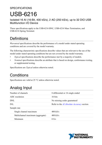
OverviewMake your projects to go green this summer with our specialized USB/Solar LithiumIon Polymer Battery charger! This charger is a very unique design, perfect for outdoorprojects, or DIY iPod chargers. We've spent over a year testing and tinkering with thischarger to come up with a plug and play solution to charging batteries with the sunand we're really pleased with what we ended up with.Easy to use! Pick up any of our many 3.7V/4.2V LiIon batteries (https://adafru.it/aN5),and a 6V solar panel (https://adafru.it/aN6). Plug the battery into the BATT port usinga 2-pin JST cable and the solar panel into the DC jack. Put the solar panel outside(and keep the battery out of the sun, it needs to be kept shaded!) to start charging.You can power another project like a Mintyboost at the same time by connecting tothe LOAD output port 3.7V/4.2V Lithium Ion or Lithium Polymer battery charger Charge with 5-6V DC, USB or 6V solar panel! Too dark out? Use a USB mini-B cable (http://adafru.it/260) or a 5V DC adapter (http://adafru.it/276) Automatic charging current tracking for high efficiency use of any wattage solarpanel Use any 6V solar panel (6V seems to work best, 5.5V may work, 5V does notwork) Three color indicator LEDs - Power good, Charging and Done Low Battery Indicator (fixed at 3.1V) with LED output on (labeled CHRG) Adafruit IndustriesPage 3 of 30
Set for 500mA max charge rate, can be adjusted from 50mA up to 1A bysoldering in a resistor Will always draw the most current possible from a solar cell - up to the maxcharge rate! Smart load sharing automatically uses the input power when available, to keepbattery from constantly charging/discharging Temperature monitoring of battery by soldering in a 10K NTC thermistor (http://adafru.it/372) (not included) - suggested for outdoor projects where the batterymay get hot (50 C) or cold (0 C). Adafruit IndustriesPage 4 of 30
FAQIs this a MPPT tracker?This is not a true MPPT tracker, for information on why we did not design it as atrue MPPT, read our design notes! (https://adafru.it/aN7)Why didn't you make this an MPPT?For low power solar charging of lithium ion's, its not necessarily a better way tocharge. For information on why we did not design it as a true MPPT, read ourdesign notes! (https://adafru.it/aN7)BUT I HEARD THAT MPPT IS THE BEST!!For large multi-watt solar arrays that are charging lead acid batteries, you will wantto get an MPPT charger. For small cells, its not necessarily more efficient. Forinformation on why we did not design it as a true MPPT, read our designnotes! (https://adafru.it/aN7)OK so how does it work?Good question! For information on how this charger works, read our designnotes! (https://adafru.it/aN7)What solar panels can I use?Use any rigid, flexible, monocrystal, polycrystal, etc panels with 6V rating (12 'cells')for the best performanceWe've tried 5V panels and they don't work. 5.5V panels sometimes work, 6V isreally the best!Can I charge with a solar panel on my windowsill?The charger will draw as much current as possible, but the efficiency of the panelwill be much lower. Solar panels must not have any glass or shade to workefficiently, they must be outside, pointed as best as possible directly at the sun! Adafruit IndustriesPage 5 of 30
Both the Charge and Done LEDs are on and the battery isnot charging.This is a fault condition detected by the charger. Most often it is a batteryproblem. This can happen if the battery is allowed to discharge completely. Theprotection circuits on some LiPo cells require the battery to be disconnected inorder to reset the circuit after an over-discharge cutoff event. Often justdisconnecting and reconnecting the battery will allow it to charge again.Solar Charger PreparationInstalling the CapacitorThe first thing to do before starting to charge with a solar panel is to install the largefiltering capacitor. This capacitor is necessary to stabilize the panel a little, and sincewe're going to charge with a lot of current, the capacitor needs to be pretty big. Thereis a spot on the PCB for the capacitor, you can of course install it directly there bysoldering the wires of the capacitor into the pads.Make sure to check the polarity of the capacitor, make sure the positive lead ofthe capacitor goes into the pad marked !If you're low on space, you can solder wires to the capacitor and then install it a littlefarther away. Just remember to use heatshrink to keep the capacitor legs fromshorting. If you want you can bend the capacitor over a bit as well, but dont have ittouch the hot charging chip (the black square in the middle of the PCB)! Adafruit IndustriesPage 6 of 30
Next you will have to connect up your solar panel. Panels sometimes come 'bare' (nowires), with just wires, or with a connector of some sort. You may need to splice aconnector onto the panel to match the 5.5/2.1mm (or 4mm on older charger) DC jackon the adapter.Solar Panel PreparationSplice or Adapt?The first verison of the solar charger came with a 4mm DC barrel jack on it. On olderversions (4mm) it would come with a converter cable. If you have a newer v2 charger (June 2013 ), connect a 2.1mm Terminal BlockAdapter (http://adafru.it/369) onto the panel using basic wires, or a 1.3mm to2.1mm adapter cable (http://adafru.it/2788) then plug that into the 2.1mm adapter.This is the fastest method If you have an older v1 charger, you can use the terminal block method aboveOR cut the adapter cable in half and splice the 4mm connector onto the panel.The panel will plug right into the board but its more work.Voltaic Panels with 1.3mm ConnectorsGrab one of our adapter cables, it will let you plug in the solar panel directly (http://adafru.it/2788) Adafruit IndustriesPage 7 of 30
Other 6V Solar PanelsIf you have a panel with something other than 2.1mm or 1.3mm connector, you'll needto remove any existing connector. Cut off whatever connector is onGently remove the outer casing without nipping the inner wires. Adafruit IndustriesPage 8 of 30
Strip and tin the inner wires. Adafruit IndustriesPage 9 of 30
Method 1For this you'll need a 2.1mm Terminal Block Adapter (http://adafru.it/369) but its reallysimple. Just open up the screw terminals, slide the red wire into the hole and theblack wire into the - hole and retighten! Now you can just plug it directly into thecharger (or adapter cable). Adafruit IndustriesPage 10 of 30
If You Have a Pre-2013 Solar ChargerThis method is a little tougher, but results in a nicer cable. You'll need someheatshrink as well as some item with a 2.1mm DC barrel plug (like the 2.1mm adapter)Cut off anything on the opposite end.And carefully strip off the outer sheath. Adafruit IndustriesPage 11 of 30
You'll want some longer wires on this side, maybe 1.5" (3-4 cm).Strip just the ends of the wires and tin them. Adafruit IndustriesPage 12 of 30
Place a big piece of heatshrink onto the cable, and then two shorter and smallerpieces on each of the wires.Solder red to red and black to black, keep the heatshrink away from your solderingiron since it may shrink too fast! Adafruit IndustriesPage 13 of 30
After the solder cools off, pull the smaller shrink onto the wires and heatshrink them! Adafruit IndustriesPage 14 of 30
Then pull the big piece over everything!And heatshrink it (with a hot air gun if you have one, or carefully with a lighter if youdon't). Adafruit IndustriesPage 15 of 30
That's it! Check with a multimeter, in the sun, to verify that you have a open circuitvoltage on the plug.Using the ChargerSolar ChargingSolar charging is easy, don't forget to prepare your solar panel and solder in theelectrolytic capacitor beforehand! (https://adafru.it/aN8)Once you've done that, you can simply plug in the solar panel into the DC jack - lookfor the PWR GOOD LED to indicate that the solar panel is providing power and then Adafruit IndustriesPage 16 of 30
plug the battery into the BATT slot in the left. Use only 3.7V/4.2V lithium ion/polymerbatteries.We have a tutorial about the batteries in case you have some questions about how touse them. (https://adafru.it/aN9)When the CHRG charging light is lit, the battery is being charged. Make sure to havethe panel facing direct sunlight not shaded and not behind any glass or plastic! whenthe battery is full, you'll see the green DONE LED light up.USB & DC ChargingOf course, sometimes is just really dark out and you can't solar charger, so there's aUSB port on the board as well. Use any mini-B cable to plug in and charge.If there is something connected to the DC jack, it will mechanically disconnect themini USB connector so be sure to unplug the solar panel when USB chargingYou can also connect a DC wall plug adapter directly into the jack, just make sure its a5.5mm/2.1mm inner diameter connector, which is very common! Adafruit IndustriesPage 17 of 30
If you need the DC power for something else, you can also connect to the DC inputvia the 0.1" breakout. While you can feed power into the breakout pins as well, it's notpolarity protected so make sure you use a schottky diode or just be really careful.Indicator LEDsThere are three status LEDs on the charger, which you'll find very handy!The red PWR LED indicates that there is good power connected to the charger. If thisLED is not lit, something is wrong with the power supplyThe orange CHRG LED indicates current charging status. When this LED is lit, thecharger is working to charge up a battery! It also acts as a low battery indicator (fixedat 3.1V) when no power is connected. So, if you don't have USB/Solar wired up, whenthe battery voltage drops below 3.1V, the orange LED will come on.The green DONE LED is pretty easy to understand as well - when it's lit the battery ischarged up! Very handy for when you want to know that everything is done.If you need to connect larger LEDs or a microcontroller up to these status pins, youcan us the STATUS 0.1" breakout on the bottom edge of the PCB. The pins are opendrain, so they will short to ground when 'active' and float when 'inactive' - you'll wantto use a pullup resistor if you need a digital signal or connect LEDs just like shownbelow on the schematic, if you want bigger lights. Adafruit IndustriesPage 18 of 30
Load SharingThe MCP73871 chip in the usb/solar charger has a very nifty feature called 'loadsharing.' Say you have an every day lipoly charger and you want to use the battery while its charging. To do this, you might connect the project directly to the batteryoutput. This means, however, that the charger is both charging a battery and drivingyour project at the same time. The charger is working extra hard and the battery isbeing charged and discharged constantly.As an improvement, this design has a pass transistor inside the chip, connected to theoutput load from the input voltage, so that you dont lose efficiency from charging/discharging the battery. When the USB/Solar charger is powered from a USB port or Adafruit IndustriesPage 19 of 30
panel, the load current goes directly from the input voltage to the output. If thecurrent required is higher than what the panel or USB port can provide, the current issupplemented by the lipo battery, up to 1.8AThe smart load sharing means that the LOAD output can be as high as 6VDC if indirect sun because it will draw current directly from the 6V panel instead of fromthe battery. If using this with an electronic project, make sure it is OK for up to6VDC input or use a low-dropout-regulator (LDO) to regulate the voltage down.This is all managed at the same time as the solar current maximization. Simply plug inthe lipoly battery on the left into the BATT port and connect your project up thru the LOAD port on the right.Temperature MonitoringIf you plan to have your project outside or unattended, we suggest addingtemperature sensing to keep the charger from overheating the battery or attemptingto charge when the battery is too hot or cold. Adafruit IndustriesPage 20 of 30
Simply remove the 10K surface mount resistor from the THERM pads (or cut the tracegoing to it), and solder in a 10K NTC thermistor (http://adafru.it/372). Test out thesystem by trying to charge while you place the thermistor in a freezer or against someice, as well as in a cup of 50 C hot water. The charger should stop charging thebattery. Once you are sure it is working, attach the sensing element (the epoxy bulb inthis case) so it is resting against the battery.Adjusting the Max Charge CurrentThe USB/Solar charger comes with a preset rate of 500mA which will work great forUSB ports, USB wall adapters and solar panels up to 3 Watts. If you have a projectthat uses a larger panel, or perhaps some other sort of setup, you can easily adjustthe current by soldering a resistor into the PROG pads. Adafruit IndustriesPage 21 of 30
The current is set by 1000/RPROG Amps, where RPROG is the resistance. So for 2Kohms, that would make it 1000/2000 0.5 A 500 mA. If you want 1A, you woulduse a 1K ohm resistor. If you want to increase the current, you need to decrease theresistance, so you can just solder over the existing 2K. So for example, solderinganother 2K resistor into RPROG will give you 1K total resistance and 1000 mA currentdraw. See above for a 2.2K resistor soldered for about 950mA of max current draw. Ifyou want to set the max current draw lower, you'll need to remove the 2K resistor.Adding External LEDsIf you are placing the charger in a box, you may want to have external LEDs forindicating charge state. This is easy! Simply use any 3mm, 5mm or 10mm LEDs youwish and 1K resistors and wire them like so: Adafruit IndustriesPage 22 of 30
Design NotesIs this a Max Power Point Tracker (MPPT)?This design is not a 'true' MPPT, and we did that for a reason! Max power pointtrackers work by 'tracking' the voltage and current curve of a solar panel so that thetotal Power (Voltage * Current) is maximized. This means that as the light changes, thevoltage and current must be carefully tracked. In general, the way controllers performMPPT is to have a DC/DC converter - that's because to have the best powerconversion you'll want DC/DC not linear converters (that lose any excess voltage asheat). For example, say you want to charge a 6V lead acid battery and you have a 12V(approx) panel. The voltage will range between 9V and 14V depending on currentdraw and visible light. The buck converter will do its best to keep the current draw sothat the total power available at the output is maximized.This diagram from Linear (https://adafru.it/CbQ) is really good at describing how itworks: Adafruit IndustriesPage 23 of 30
The Green lines show the I-V curve of the panel for a given light condition. As thelight increases the voltages stay sort of the same but the amount of current you candraw goes up! If you can keep the DC/DC converter operating on the red line, that'sthe maximum power.However, there are some side effects to using a MPPT design.First is that DC/DC converters are expensive, and adding a DC/DC converter to a LiPocharger chip increases the cost by 2x. For small panels, if the MPPT increases theefficiency by 30% but you can double the panel size for the same price increase, itmight be easier to just go with a larger panel.Second is that DC/DC converters are not necessarily more efficient than a linearconverter at low voltages and currents. At the voltages we're talking about, a 6Vpanel charging a 4V battery, the max power point will tend to be around 5V - only avolt above the battery. Considering there's a 0.5V drop with the input diode, theadded inefficiency of a DC/DC converter is about equivalent to the extra voltage dropused by the linear charger. For this reason, you tend to see MPPT controllers only formulti-ampere chargers for big lead acid batteries and really big panels.So the upshot is.If your panel voltage is 1V above your battery charging voltage, your current draw isunder an Ampere, and you control the current draw to keep the voltage steady ataround the 'max power voltage' (the red line up above), it's possible to get near-MPPT Adafruit IndustriesPage 24 of 30
performance, without the complexity of a DC/DC converter, and without the highprice. That's what the design of this charger does.Why a special solar charger?We've had a lot of customers that are interested in making solar powered projects, sowe wanted to make a lipo charger board that is specifically designed with Solar &USB charging in mind. We'll explain why.Most people try to plug a solar panel directly into a lipo charger and while it sort of works, the battery takes forever to charge because the efficiency is terrible! That'sbecause most lipo chargers are meant to plug into a USB port or wall, and are verysimple in their design. USB ports supply 5V at up to 500mA and they're pretty solid the voltage doesn't change much even at the max current draw. So when you plug acharger into a computer with a USB port, they just draw 500mA or so and happilychug away. Same goes for wall adapters. The voltage and current limits are keptsteady.Solar panels are a little different, the voltage and current vary constantly dependingon sunlight available. They are unstable! That instability confuses battery chargers,which causes them to do one of two things: rapidly turn on and off as they try to drawmore current from the panel than possible and/or draw much less current than theycan, to keep the voltage from collapsingHere is a diagram of a single solar cell, in various light conditions (the coloredrainbow lines): Adafruit IndustriesPage 25 of 30
We find these diagrams common but a bit confusing. So we'll show how to use them.Pick the top red line (maximum light) and start at the very right of the line where itmeats the horizontal scale. This is the current (I) 0 point. We're drawing no current and the voltage of the cell is 0.5V. 0.5V is the open circuit voltage. Keep following thegraph up and to the left. As the current draw increases, the voltage drops slightly untilwe reach the point of drawing 38mA (0.038A). At this point, the voltage is around0.4V. Next draw a bit more current, moving to the left some more and the voltagestarts collapsing.We can try to draw more current but as you can see, drawing even atiny bit more than 38mA makes the cell voltage drop to 0V. 38mA is the short circuitcurrentDepending on the light conditions, the amount of maximum current can range, from38mA (red) to 32 mA (orange) down to 5mA (yellow) or even lower. Solar cells can bemade larger (the short circuit current is bigger) but the voltage of the cell is fixed at0.5V open circuit - it's just part the physics of the cell. However, you can connect abunch of cells in series to add them up. A 6V panel has 12 cells (12 * 0.5V 6V)Now you can see what happens if you connect a 6V solar panel to a lipoly charger. Aslong as the current being drawn by the charger is less than the panel's short circuitcurrent at that light condition, everything is peachy. The moment the light changeseven a little, and the current the lipo charger wants is higher than the short circuitcurrent, the charger becomes unstable: it will draw too much current, which will causethe voltage to collapse, which causes the charger to turn off, which reduces the Adafruit IndustriesPage 26 of 30
current draw, which makes the panel voltage recover, which turns on the chargeragain, which then draws too much current, and the cycle repeats.You can see this happen in the image from my scope below:The scale is 1V per square, and the 0V point is one square above the bottom of thedisplay (see the 2- on the left) The open circuit voltage of the panel is about 6.5V,the lipo charger draws some current and quickly the panel voltage collapses. After250 us, the charger tries again, but fails again. The lipo charger may seem to becharging because the CHRG light is on but really its doing a poor job of it!Solar Optimization!OK so how do we fix this problem? The issue we have here is that the voltagecollapses during high current draw. We need to find a way to keep the lipo chargerfrom drawing too much current, and backing off when the voltage starts to droop. Welooked high and low and finally found a chip that has something like this built in. TheMCP73871 calls it Voltage Proportional Charge Control (VPCC) and basically, it doesprecisely what we want. We can set the voltage to a point just above the batterycharge voltage point (say 4.5V) and then instruct the charger to draw as much currentas possible. It will automatically increase/reduce the charge rate to keep the voltagehigher than 4.5V! Adafruit IndustriesPage 27 of 30
In this case, we set the voltage using two resistors, the voltage divider ends upstabilizing it at 4.5V. Because the voltage collapse of a panel is really sudden, westill end up needing a little more help stabilizing the panel. We do that by adding aBFC (Big Freaking Capacitor).This schottky diode charges a 4700uF capacitor from the panel - the diode preventsthe capacitor from draining back into the panel. Adafruit IndustriesPage 28 of 30
DownloadsFiles MCP73871 datasheet (https://adafru.it/aMO) Fritzing object in Adafruit Fritzing library (https://adafru.it/aP3) EagleCAD Board / Layout & Schematic files on Github (https://adafru.it/aMP)Schematic & Fabrication Print Adafruit IndustriesPage 29 of 30
Adafruit IndustriesPage 30 of 30
Nov 15, 2021 · Make your projects to go green this summer with our specialized USB/Solar Lithium Ion Polymer Battery charger! This charger is a very unique design, perfect for outdoor projects, or DIY iPod chargers. We've spent over a year testing and tinkering with this charger to come up with a


![[ANS AQT80] - FCC ID](/img/3/user-manual-pdf-2735955.jpg)