Transcription
VEER SURENDRA SAI UNIVERSITY OF TECHNOLOGY BURLA, ODISHA, INDIADEPARTMENT OF ELECTRICAL ENGINEERINGLecture Notes onPower ElectronicsSubject code – BEE16026th Semester B.Tech. (Electrical Engineering)
DisclaimerThis document does not claim any originality and cannot be used as a substitute forprescribed textbooks. The information presented here is merely a collection by thecommittee members for their respective teaching assignments. Various sources asmentioned at the end of the document as well as freely available material from internetwere consulted for preparing this document. The ownership of the information lies with therespective authors or institutions. Further, this document is not intended to be used forcommercial purpose and the committee members are not accountable for any issues, legalor otherwise, arising out of use of this document. The committee members make norepresentations or warranties with respect to the accuracy or completeness of the contentsof this document and specifically disclaim any implied warranties of merchantability orfitness for a particular purpose. The committee members shall be liable for any loss of profitor any other commercial damages, including but not limited to special, incidental,consequential, or other damages.
(6TH SEMESTER)POWER ELECTRONICS (3-1-0)MODULE-I (10 HOURS)Thyristors, Static V-I Characteristics of SCR, TRIAC, GTO & IGBT, Turn-On & Turn-OFFMechanism of SCR, Gate Turnoff Thyristor (GTO) .Power BJTs . Power MOSFETs Insulated GateBipolar Transistors (IGBTs) - Basic Structure and VI Characteristics. Static, dynamic andthermalcharacteristics. Protection, cooling and mounting techniques. Series and Parallel operation ofdevices.Triggering and basics of driver circuits. Different types of commutation schemes: Natural andForcedcommutation.MODULE-II (10 HOURS)1-Phase Half & Full Wave Controlled Rectifier with various kinds of loads (R, R-L-E(motor)).Midpoint and Bridge type converters. Half Controlled and Fully Controlled Bridge circuits,differentwaveforms, Input Line Current Harmonics, Power factor, current distortion and displacementfactorsInverter Mode of Operation. Continuous and discontinuous modes, Effect of sourceinductanceassuming constant load current. Effect of freewheeling diode. Three phase bridge convertersfordifferent types of load with constant load current, different waveforms. 180 and 120 degreeoperations.MODULE-III (10 HOURS)DC-DC Converters: Classification of types of choppers, One, Two and Four quadrantoperations,Step up and down choppers, Analysis of Type-A chopper, Single-and two quadrant operationwith DCmotor load.AC-AC Converters: Single-phase mid-point and bridge types of step-up and step-downCycloconverters.Single phase AC Voltage regulators and its basic analysis.MODULE-IV (10 HOURS)Single-phase Half and Full bridge Inverter, Pulse Width Modulated (PWM) technique forvoltagecontrol, SPWM Technique 1-phase inverters, Auxiliary Commutated (Mc-Murray) andComplementary Commutated (Mc-Murray Bedford) Inverters, Three-phase Voltage SourceBridgetype of Inverters. (120 and 180 Degree conduction modes), Current Source Inverter.Applications: UPS, SMPS, Induction Heating, Electronic Ballast, AC/DC drives speedcontrol.
MODULE - 1
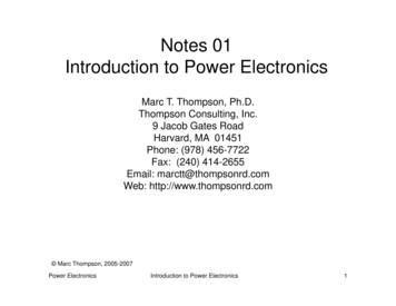
POWER ELECTRONICSThe control of electric motor drives requires control of electric power. Power electronics haveeased the concept of power control. Power electronics signifies the word power electronicsand control or we can say the electronic that deal with power equipment for power control.Main power sourceRef ircuitLoadFeedback SignalPower electronics based on the switching of power semiconductor devices. With thedevelopment of power semiconductor technology, the power handling capabilities andswitching speed of power devices have been improved tremendously.Power Semiconductor DevicesThe first SCR was developed in late 1957. Power semiconductor devices are broadlycategorized into 3 types:1. Power diodes2. Transistors3. Thyristors(600V,4500A)(10KV,300A,30MW)Thyristor is a four layer three junction pnpn semiconductor switching device. It has 3terminals these are anode, cathode and gate. SCRs are solid state device, so they are compact,possess high reliability and have low loss.
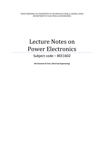
SCR is made up of silicon, it act as a rectifier; it has very low resistance in the forwarddirection and high resistance in the reverse direction. It is a unidirectional device.Static V-I characteristics of a ThyristorThe circuit diagram for obtaining static V-I characteristics is as shownAnode and cathode are connected to main source voltage through the load. The gate andcathode are fed from source 𝐸𝑆 .A typical SCR V-I characteristic is as shown below:
𝑉𝐵𝑂 Forward breakover voltage𝑉𝐵𝑅 Reverse breakover voltage𝐼𝑔 Gate current𝑉𝑎 Anode voltage across the thyristor terminal A,K.𝐼𝑎 Anode currentIt can be inferred from the static V-I characteristic of SCR. SCR have 3 modes ofoperation:1. Reverse blocking mode2. Forward blocking mode ( off state)3. Forward conduction mode (on state)1. Reverse Blocking ModeWhen cathode of the thyristor is made positive with respect to anode with switch openthyristor is reverse biased. Junctions 𝐽1 and 𝐽2 are reverse biased where junction 𝐽2 isforward biased. The device behaves as if two diodes are connected in series with reversevoltage applied across them. A small leakage current of the order of few mA only flows. As the thyristor isreverse biased and in blocking mode. It is called as acting in reverse blockingmode of operation. Now if the reverse voltage is increased, at a critical breakdown level calledreverse breakdown voltage 𝑉𝐵𝑅 ,an avalanche occurs at 𝐽1 and 𝐽3 and the reverse
current increases rapidly. As a large current associated with 𝑉𝐵𝑅 and hence morelosses to the SCR.This results in Thyristor damage as junction temperature may exceed its maximumtemperature rise.2. Forward Blocking ModeWhen anode is positive with respect to cathode, with gate circuit open, thyristor is said tobe forward biased.Thus junction 𝐽1 and 𝐽3 are forward biased and 𝐽2 is reverse biased. As the forwardvoltage is increases junction 𝐽2 will have an avalanche breakdown at a voltage calledforward breakover voltage𝑉𝐵𝑂 . When forward voltage is less then 𝑉𝐵𝑂 thyristor offers highimpedance. Thus a thyristor acts as an open switch in forward blocking mode.3. Forward Conduction ModeHere thyristor conducts current from anode to cathode with a very small voltage dropacross it. So a thyristor can be brought from forward blocking mode to forwardconducting mode:1. By exceeding the forward breakover voltage.2. By applying a gate pulse between gate and cathode.During forward conduction mode of operation thyristor is in on state and behave like aclose switch. Voltage drop is of the order of 1 to 2mV. This small voltage drop is due toohmic drop across the four layers of the device.Different turn ON methods for SCR1. Forward voltage triggering2. Gate triggering3.𝑑𝑣𝑑𝑡triggering4. Light triggering5. Temperature triggering1. Forward voltage triggering
A forward voltage is applied between anode and cathode with gate circuit open. Junction 𝐽1 and 𝐽3 is forward biased.Juntion 𝐽2 is reverse biased.As the anode to cathode voltage is increased breakdown of the reverse biased junction𝐽2 occurs. This is known as avalanche breakdown and the voltage at which thisphenomena occurs is called forward breakover voltage.The conduction of current continues even if the anode cathode voltage reduces below𝑉𝐵𝑂 till 𝐼𝑎 will not go below𝐼ℎ . Where 𝐼ℎ is the holding current for the thyristor.2. Gate triggeringThis is the simplest, reliable and efficient method of firing the forward biased SCRs. FirstSCR is forward biased. Then a positive gate voltage is applied between gate and cathode. Inpractice the transition from OFF state to ON state by exceeding 𝑉𝐵𝑂 is never employed as itmay destroy the device. The magnitude of 𝑉𝐵𝑂 , so forward breakover voltage is taken as finalvoltage rating of the device during the design of SCR application.First step is to choose a thyristor with forward breakover voltage (say 800V) higher than thenormal working voltage. The benefit is that the thyristor will be in blocking state with normalworking voltage applied across the anode and cathode with gate open. When we require theturning ON of a SCR a positive gate voltage between gate and cathode is applied. The pointto be noted that cathode n- layer is heavily doped as compared to gate p-layer. So when gatesupply is given between gate and cathode gate p-layer is flooded with electron from cathoden-layer. Now the thyristor is forward biased, so some of these electron reach junction 𝐽2 .As aresult width of 𝐽2 breaks down or conduction at 𝐽2 occur at a voltage less than 𝑉𝐵𝑂 .As 𝐼𝑔increases 𝑉𝐵𝑂 reduces which decreases then turn ON time. Another important point isduration for which the gate current is applied should be more then turn ON time. This means
that if the gate current is reduced to zero before the anode current reaches a minimum valueknown as holding current, SCR can’t turn ON.In this process power loss is less and also low applied voltage is required for triggering.3. dv/dt triggeringThis is a turning ON method but it may lead to destruction of SCR and so it must be avoided.When SCR is forward biased, junction 𝐽1 and 𝐽3 are forward biased and junction 𝐽2 isreversed biased so it behaves as if an insulator is place between two conducting plate. Here 𝐽1and 𝐽3 acts as a conducting plate and 𝐽2 acts as an insulator. 𝐽2 is known as junction capacitor.So if we increase the rate of change of forward voltage instead of increasing the magnitude ofvoltage. Junction 𝐽2 breaks and starts conducting. A high value of changing current may𝑑𝑣damage the SCR. So SCR may be protected from high 𝑑𝑡 .𝑞 𝑐𝑣𝐼𝑎 𝑐𝐼𝑎 𝛼𝑑𝑣𝑑𝑡𝑑𝑣𝑑𝑡4. Temperature triggeringDuring forward biased, 𝐽2 is reverse biased so a leakage forward current always associatedwith SCR. Now as we know the leakage current is temperature dependant, so if we increasethe temperature the leakage current will also increase and heat dissipitation of junction𝐽2 occurs. When this heat reaches a sufficient value 𝐽2 will break and conduction starts.Disadvantages
This type of triggering causes local hot spot and may cause thermal run away of the device.This triggering cannot be controlled easily.It is very costly as protection is costly.5. Light triggeringFirst a new recess niche is made in the inner p-layer. When this recess is irradiated, then freecharge carriers (electron and hole) are generated. Now if the intensity is increased above acertain value then it leads to turn ON of SCR. Such SCR are known as Light activated SCR(LASCR).Some definitions:Latching currentThe latching current may be defined as the minimum value of anode current which at mustattain during turn ON process to maintain conduction even if gate signal is removed.Holding currentIt is the minimum value of anode current below which if it falls, the SCR will turn OFF.Switching characteristics of thyristorsThe time variation of voltage across the thyristor and current through it during turn onand turn off process gives the dynamic or switching characteristic of SCR.Switching characteristic during turn onTurn on timeIt is the time during which it changes from forward blocking state to ON state. Total turnon time is divided into 3 intervals:1. Delay time2. Rise time3. Spread timeDelay timeIf 𝐼𝑔 and 𝐼𝑎 represent the final value of gate current and anode current. Then the delay timecan be explained as time during which the gate current attains 0.9 𝐼𝑔 to the instant anodecurrent reaches 0.1 𝐼𝑔 or the anode current rises from forward leakage current to 0.1 𝐼𝑎 .1. Gate current 0.9 𝐼𝑔 to 0.1 𝐼𝑎 .2. Anode voltage falls from 𝑉𝑎 to 0.9𝑉𝑎 .3. Anode current rises from forward leakage current to 0.1 𝐼𝑎 .
Rise time (𝒕𝒓 )Time during which1. Anode current rises from 0.1 𝐼𝑎 to 0.9 𝐼𝑎2. Forward blocking voltage falls from 0.9𝑉𝑎 to 0.1𝑉𝑎 . 𝑉𝑎 is the initial forward blockingvoltage.Spread time (𝒕𝒑 )1. Time taken by the anode current to rise from 0.9𝐼𝑎 to𝐼𝑎 .2. Time for the forward voltage to fall from 0.1𝑉𝑜 to on state voltage drop of 1 to 1.5V.During turn on, SCR is considered to be a charge controlled device. A certain amountof charge is injected in the gate region to begin conduction. So higher the magnitudeof gate current it requires less time to inject the charges. Thus turn on time is reducedby using large magnitude of gate current.How the distribution of charge occurs?As the gate current begins to flow from gate to cathode with the application of gatesignal. Gate current has a non uniform distribution of current density over the cathodesurface. Distribution of current density is much higher near the gate. The density decreaseas the distance from the gate increases. So anode current flows in a narrow region neargate where gate current densities are highest. From the beginning of rise time the anodecurrent starts spreading itself. The anode current spread at a rate of 0.1mm/sec. Thespreading anode current requires some time if the rise time is not sufficient then the anodecurrent cannot spread over the entire region of cathode. Now a large anode current isapplied and also a large anode current flowing through the SCR. As a result turn on lossesis high. As these losses occur over a small conducting region so local hot spots may formand it may damage the device.Switching Characteristics During Turn OffThyristor turn off means it changed from ON to OFF state. Once thyristor is oON there isno role of gate. As we know thyristor can be made turn OFF by reducing the anodecurrent below the latching current. Here we assume the latching current to be zeroampere. If a forward voltage is applied across the SCR at the moment it reaches zero thenSCR will not be able to block this forward voltage. Because the charges trapped in the 4layer are still favourable for conduction and it may turn on the device. So to avoid such acase, SCR is reverse biased for some time even if the anode current has reached to zero.So now the turn off time can be different as the instant anode current becomes zero to theinstant when SCR regains its forward blocking capability.𝑡𝑞 𝑡𝑟𝑟 𝑡𝑞𝑟Where,
𝑡𝑞 is the turn off time,𝑡𝑟𝑟 is the reverse recovery time, 𝑡𝑞𝑟 is the gate recovery timeAt 𝑡1 anode current is zero. Now anode current builds up in reverse direction with same𝑑𝑣𝑑𝑡slope. This is due to the presence of charge carriers in the four layers. The reverserecovery current removes the excess carriers from 𝐽1 and 𝐽3 between the instants 𝑡1 and𝑡3 .At instant 𝑡3 the end junction 𝐽1 and 𝐽3 is recovered. But 𝐽2 still has trapped charges whichdecay due to recombination only so the reverse voltage has to be maintained for somemore time. The time taken for the recombination of charges between 𝑡3 and 𝑡4 is calledgate recovery time 𝑡𝑞𝑟 . Junction 𝐽2 recovered and now a forward voltage can be appliedacross SCR.The turn off time is affected by:1. Junction temperature2. Magnitude of forward current𝑑𝑖𝑑𝑡during commutation.Turn off time decreases with the increase of magnitude of reverse applied voltage.GTO(Gate turn off thyristor)
A gate turn off thyristor is a pnpn device. In which it can be turned ON like an ordinary SCRby a positive gate current. However it can be easily turned off by a negative gate pulse ofappropriate magnitude.Conventional SCR are turned on by a positive gate signal but once the SCR is turned on gateloses control over it. So to turn it off we require external commutation circuit. Thesecommutation circuits are bulky and costly. So due to these drawbacks GTO comes intoexistence.The salient features of GTO are:1. GTO turned on like conventional SCR and is turned off by a negative gate signal ofsufficient magnitude.2. It is a non latching device.3. GTO reduces acoustic and electromagnetic noise.It has high switching frequency and efficiency.A gate turn off thyristor can turn on like an ordinary thyristor but it is turn off by negativegate pulse of appropriate magnitude.DisadvantageThe negative gate current required to turn off a GTO is quite large that is 20% to 30 % ofanode currentAdvantageIt is compact and cost lessSwitching performance
1. For turning ON a GTO first TR1is turned on.2. This in turn switches on TR2 so that a positive gate current pulse is applied to turn on theGTO.3. Thyristor 𝑇1 is used to apply a high peak negative gate current pulse.Gate turn-on characteristics1. The gate turn on characteristics is similar to a thyristor. Total turn on time consists ofdelay time, rise time, spread time.2. The turn on time can be reduced by increasing its forward gate current.
GATE TURN OFFTurn off time is different for SCR.Turn off characteristics is divied into 3 pd1. Storage time2. Fall time3. Tail timeTq ts tf ttAt normal operating condition gto carries a steady state current.The turn off processstarts as soon as negative current is applied after t 0.STORAGE TIMEDuring the storagepd the anode voltage and current remains constant.The gate current risesdepending upon the gate circuit impedance and gate applied voltage.The beginning of pd is as soonas negative gate current is applied.The end of storage pd is marked by fall in anode current andrise in voltage,what we have to do is remove the excess carriers.the excess carriers are removed bynegative carriers.
FALL TIMEAfter ts, anode current begins to fall rapidly and anode voltage starts rising.After falling to a certainvalue,then anode current changes its rate to fall.this time is called fall time.SPIKE IN VOLTAGEDuring the time of storage and fall timethere is achange in voltage due to abrupt current change.TAIL TIMEDuring this time ,the anode current and voltage continues towards the turn off values.The transientovershoot is due to the snubber parameter and voltage stabilizes to steady state value.
THE TRIACAs SCR is a unidirectional device,the conduction is from anode to cathode and not fromcathode to anode. It conducts in both direction.It is a bidirectional SCR with three terminal.TRIAC TRIODE ACHere it is considered to be two SCRS connected in anti parallel.As it conducts in bothdirection so it is named as MT1,MT2 and gate G.SALIENT FEATURES1.Bi directional triode thyristor2.TRIAC means triode that works on ac3.It conduct in both direction4.It is a controlled device
5.Its operation is similar to two devices connected in anti parallel with common gateconnection.6.It has 3 terminals MT1,MT2 and gate GIts use is control of power in ac.POWER BJTPower BJT means a large voltage blocking in the OFF state and high current carrying capability in theON state. In most power application, base is the input terminal. Emitter is the common terminal.Collector is the output terminal.SIGNAL LEVEL OF BJTn doped emitter layer ,doping of base is more than collector.Depletion layer exists more towardsthe collector than emitter
POWER BJT CONSTRUCTIONThe maxium collector emitter voltage that can be sustained across the junction, when it iscarrying substantial collector current.Vceo maxium collectorand emitter voltage that can be sustain by the device.Vcbo collector base breakdown voltage with emitter openPRIMARY BREAKDOWNIt is due to convention avalanche breakdown of the C-B junction and its associated largeflow of current.The thickness of the depletion region determines the breakdown voltage ofthe transistor.The base thickness is made as small as possible,in order to have goodamplification capability. If the thickness is too small, the breakdown voltage iscompromised.So a compromise has to be made between the two.
THE DOPING LEVELS1.The doping of the emitter layer is quite large.2.The base doping is moderate.3.n- region is lightly doped.4.n region doping level is similar to emitter.1.THICKNESS OF DRIFT REGIONIt determines the breakdown length of the transistor.2.THE BASE THICKNES –Small base thickness- good amplification capabilityToo small base thickness- the breakdown voltage of the transistor has ti be compromised.For a relatively thick base,the current gain will be relatively small.so it is increase thegain.Monolithicesigns for darlington connected BJT pair have been deveploed.SECONDARY BREAKDOWNSecondary breakdown is due to large power disspation at localized site within the semiconductor.PHYSICS OF BJT OPERATIONThe transistor is assumed to operate in active region. There is no doped collector driftregion. It has importance only in switching operation, in active region of operation.B-E junction is forward biased and C-B junction is reverse biased. Electrons are injected intobase from the emitter. Holes are injected from base into the emitter.QUASI SATURATIONIntially we assume that, the transistor is in active region. Base current is allowed to increasethen lets see what happens.first collector rises in response to base current.So there is aincrease voltage drop across the collector load.So C-E voltage drops.Because of increase in collector current, there is a increase in voltage in drift region. Thiseventually reduces the reverse biased across the C-B junction.so n-p junction getsmaller, at some point the junction become forward bised. So now injection of holes frombase into collector drift region occurs. Charge neutrality requires the electron to be injectedin the drift region of the holes. From where these electron came. Since a large no ofelectron is supplied to the C-B junction via injection fromemitter and subsequentdiffusion across the base. As excess carrier build up in the drift region begins to occurquasi saturation region is entered. As the injected carrires increase in the drift region is
gradually shotred out and the voltage across the drift region drops. In quasi saturation thedrift region is not completely shorted out by high level injection.Hard saturation obtainedwhen excess carrier density reaches the n side.During quasi saturation, the rate of the collector fall.Hard saturation occurs when excesscarriers have completely swept across the drift region .THYRISTOR PROTECTIONOVER VOLTAGE PROTECTIONOver voltage occurring during the switching operation causes the failure of SCR.INTERNAL OVERVOLTAGEIt is due to the operating condition of SCR.
During the commutation of SCR ,when the anode current decays to zero anode currentreverses due to stored changes. First the reverse current rises to peak value, then reversecurrent reduces abruptly with large 𝑑𝑖 𝑑𝑡 . Duringseries inductance of SCR largetransient large voltage i.e 𝐿 𝑑𝑖 𝑑𝑡. is generated.EXTERNAL OVER VOLTAGEThis is due to external supply and load condition. This is because of1. The interruption of current flow in an inductive circuit.2. Lightening strokes on the lines feeding the thyristor systems.Suppose a SCR converter is fed from a transformer, voltage transient occur whentransformer primary will energise or de-energised.This overvoltages cause random turn ON of a SCR.The effect of overvoltage is minimized using1. RC circuits2. Non linear resistor called voltage clamping device.Voltage clamping device is a non linear resistor.It is connected betweencathode and anode of SCR. The resistance of voltage clamping devicedecreases with increasing voltages. During normal working condition Voltageclamping (V.C) device has high resistance, drawing only leakage current.When voltage surge appears voltage clamping device offers a low resistance and itcreate a virtual short circuit across the SCR. Hence voltage across SCR isclamped to a safe value.
When surge condition over voltage clamping device returns to high resistancestate.e.g. of voltage clamping device1.Seleniumthyrector diodes2.Metal Oxide varistors3.Avalanche diode supressorsOVER CURRENT PROTECTIONLong duration operation of SCR, during over current causes the1.junction temp. of SCR to rise above the rated value,causing permanentdamage to device.SCR is protected from overcurrent by using1.Circuit breakers2.Fast acting fusesProper co-ordination is essential because1.fault current has to be interrupted before SCR gets damaged.2.only faulty branches of the network has to be replaced.In stiff supply network,source has negligible impedance.So in such systemthe magnitude and rate of rise of current is not limited.Fault current hencejunction temp rises in a few miliseconds.POINTS TO BE NOTED1. Proper coordination between fast acting fuse and thyristor is essential.2. The fuse is always rated to carry marginal overload current overdefinite period.3. The peak let through current through SCR must be less than sub cyclerating of the SCR.4. The voltage across the fuse during arcing time is called arcing orrecovery voltage and is equal to sum of the source voltage and emfinduced in the circuit inductance during arcing time.5. On abrupt interruption of fuse current, induce emf would be high, whichresults in high arcing voltage.Circuit Breaker (C.B)C.B. has long tripping time. So it is used for protecting the device against continuousoverload current or against the surge current for long duration. In order that fuseprotects the thyristor realiably the 𝐼 2 𝑡 rating of fuse current must be less than that ofSCR.ELECTRONIC CROWBAR PROTECTION
For overcurrent protection of power converter using SCR, electronic crowbar areused. It provide rapid isolation of power converter before any damageoccurs.HEAT PROTECTIONTo protect the SCR1. From the local spots2. Temp riseSCRs are mounted over heat sinks.GATEPROTECTION-Gate circuit should also be protected from1. Overvoltages2. OvercurrentsOvervoltage across the gate circuit causes the false triggering of SCR
Overcurrent raise the junction temperature. Overvoltage protection is by zenerthe gate circuit.diode acrossINSULATED GATE BIPOLAR TRANSISTOR(IGBT)BASIC CONSTRUCTIONThe n layer substrate at the drain in the power MOSFET is substituted by p layer substrateand called as collector. When gate to emitter voltage is positive,n- channel is formed in thep- region.This n- channel short circuit the n- and n layer and an electron movement in nchannel cause hole injection from p subtrate layer to n- layer.
POWER MOSFETA power MOSFET has three terminal device. Arrow indicates the direction of currentflow. MOSFET is a voltage controlled device. The operation of MOSFET depends on flowof majority carriers only.(Circuit diagram)(circuit symbol)Switching Characteristics:The switching characteristic is influenced by1. Internal capacitance of the device.2. Internal impedance of the gate drive circuit.Total turn on time is divided into1.Turn on delay time2.Rise timeTurn on time is affected by impedance of gate drive source. During turn on delay time gateto source voltage attends its threshold value 𝑉𝐺𝑆𝑇 .After 𝑡𝑑𝑛 and during rise time gate to source voltage rise to 𝑉𝐺𝑠𝑝 , a voltage which issufficient to drive the MOSFET to ON state.The turn off process is initiated by removing the gate to source voltage. Turn off time iscomposed of turn off delay time to fall time.Turn off delay time
To turn off the MOSFET the input capacitance has to be discharged . During 𝑡𝑑𝑓 the inputcapacitance discharge from 𝑉1to 𝑉𝐺𝑠𝑝 . During 𝑡𝑓 , fall time ,the input capacitance dischargesfrom 𝑉𝐺𝑠𝑝 to 𝑉𝐺𝑆𝑇 . During 𝑡𝑓 drain current falls from 𝐼𝐷 to zero.So when 𝑉𝐺𝑠 𝑉𝐺𝑆𝑇 , MOFSET turn off is complete.Fig. Switching waveform of power MOSFETInsulated Gate Bipolar Transistor (IGBT)IGBT has high input impedance like MOFFSET and low on state power lose as in BJT.IGBT CharacteristicsHere the controlling parameter is gate emitter voltage As IGBT is a voltage controlled device.When 𝑉𝐺𝐸 is less than 𝑉𝐺𝐸𝑇 that is gate emitter threshold voltage IGBT is in off state.
Fig. aFig. b.Fig. a (Circuit diagram for obtaining V-I characteristics)characteristics)Fig. cFig. b (Static V-IFig. c (Transfer characteristic)Switching characteristics: Figure below shows the turn ON and turn OFF characteristics ofIGBTTurn on time
Time between the instants forward blocking state to forward on -state .Turn on time Delay time Rise timeDelay time Time for collector emitter voltage fall from 𝑉𝐶𝐸 to 0.9𝑉𝐶𝐸𝑉𝐶𝐸 Initial collector emitter voltage𝑡𝑑𝑛 collector current to rise from initial leakage current to 0.1IcIc Final value of collector currentRise timeCollector emitter voltage to fall from 0.9𝑉𝐶𝐸 to 0.1𝑉𝐶𝐸 .0.1Ic to IcAfter 𝑡𝑜𝑛 the device is on state the device carries a steady current of Ic and the collectoremitter voltage falls to a small value called conduction drop 𝑉𝐶𝐸𝑆 .Turn off time1) Delay time 𝑡𝑑𝑓2) Initial fall time 𝑡𝑓13) Final fall time 𝑡𝑓2𝑡𝑂𝑓𝑓 𝑡𝑑𝑓 𝑡𝑓1 𝑡𝑓2𝑡𝑑𝑓 Time during which the gate emitter voltage falls to the threshold value 𝑉𝐺𝐸𝑇 .Collector current falls from Ic to 0.9Ic at the end of the 𝑡𝑑𝑓 collector emitter voltage begins torise.Turn off time Collector current falls from 90% to 20% of its initial value Ic OR The timeduring which collector emitter voltage rise from 𝑉𝐶𝐸 to 0.1𝑉𝐶𝐸 .𝑡𝑓2 collector current falls from20% to 10% of Ic.During this collector emitter voltage rise 0.1𝑉𝐶𝐸 to final value of 𝑉𝐶𝐸 .Series and parallel operation of SCRSCR are connected in series for h.v demand and in parallel for fulfilling high currentdemand. Sting efficiency can be defined as measure of the degree of utilization on SCRs in astring.String efficiency 1.Derating factor (DRF)
1 – string efficiency.If DRF more thenno. of SCRs will more, so string is more reliable.Let the rated blocking voltage of the string of a series connected SCR is 2𝑉1 as shown in thefigure below, But in the string two SCRs are supplied a maximum voltage of 𝑉1 𝑉2.𝜂 𝑉1 𝑉22𝑉1Significance of string efficiency .Two SCRs are have same forward blocking voltage ,When system voltage is more then thevoltage rating of a single SCR. SCRs are connected in series in a string.There is a inherent variation in characteristics. So voltage shared by each SCR may not beequal. Suppose, SCR1 leakage
commercial purpose and the committee members are not accountable for any issues, legal or otherwise, arising out of use of this document. . Power electronics signifies the word power electronics and control or we can say the electronic that deal with power equipment for p