Transcription
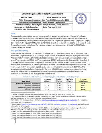
ISO 19880-1, Hydrogen Fueling Station and Vehicle Interface SafetyTechnical Report (ICHS # 116)Authors: Schneider, J.1; Dang-Nhu, G.2; Hart, N.3; Groth, K.41Bayerische Motoren Werke Aktiengesellschaft (BMW AG), Petuelring 130, 80809München, Germany2Air Liquide, 2 Rue de Clémencière, 38360 Sassenage, France3ITM Power, 22 Atlas Way, Sheffield, South Yorkshire S4 7QQ, United Kingdom4Sandia National Laboratories, 1515 Eubank, Albuquerque, NM 871231. IntroductionHydrogen Infrastructures are currently being built up to support the initialcommercialization of the fuel cell vehicle by multiple automakers. Three primarymarkets are presently coordinating a large buildup of hydrogen stations: Japan; USA;and Europe to support this. Hydrogen Fueling Station General Safety and PerformanceConsiderations are important to establish before a wide scale infrastructure isestablished.This document introduces the ISO Technical Report 19880-1 and summarizes mainelements of the proposed standard. Note: this ICHS paper is based on the draft TR19880-1 and is subject to change when the document is published in 2015.International Standards Organisation (ISO) Technical Committee (TC) 197, WorkingGroup (WG) 24, has been tasked with the preparation of the ISO standard 19880-1, todefine the minimum requirements considered applicable worldwide for the hydrogenand electrical safety of hydrogen stations. This report includes safety considerations forhydrogen station equipment and components, control systems and operation. Thefollowing systems are covered specifically in the document as shown in Figure 1:-H2 production / supply delivery systemCompressionGaseous hydrogen buffer storage;Pre-cooling device;Gaseous hydrogen dispensers.Hydrogen Fueling, Vehicle InterfaceThe draft TR 19880-1 (and current plan for the standard) also gives guidance for thefueling validation with safety considerations relevant to the interaction between thehydrogen station and hydrogen road vehicles (during fueling). Through a cross-industryrisk assessment carried out between OEMs, Hydrogen Suppliers and existing vehiclefuelling station providers & operators (e.g. oil and industrial gas companies) the1 Page
ISO 19880-1, Hydrogen Fueling Station and Vehicle Interface SafetyTechnical Report (ICHS # 116)hydrogen fueling protocol SAE J2601 and associated dispenser hardware wasevaluated.Figure 1 —Example hydrogen Fueling station illustrating scope of SO TR-19880Currently, the expected level of quality supplied at the nozzle of the dispenser is definedin the standard ISO 14687-2 (Hydrogen fuel — Product specification — Part 2: Protonexchange membrane (PEM) fuel cell applications for road vehicles).In addition, ISO TR 19880-1 has examples for hydrogen quality control, to enablingstations to reduce the amount of testing needed to validate hydrogen fuel against ISO14687-2 based on the hydrogen source.Finally, in an informative annex of the TR 19880-1 the safety distances currently appliedis documented with examples.2. The Standardization ProcessThe ISO Technical Report (TR) 19880-1, Gaseous hydrogen — Fueling stations,published in 2015, is a first step towards standardizing the hydrogen station, andproviding more up-to-date guidance than that developed as ISO TS 20100, published in2008. The goal of the ISO TC 197 WG24 is to create an all encompassing guideline forthe station and the interface between the vehicle and the hydrogen fueling station,including validation of the fueling process.The goal is to then finalize the ISO standard 19880-1 by the end of 2016 in order toalign with the need for adoption of the standard worldwide as well as with regulations inplace / being prepared around the world. Specifically, the Alternative FuelsInfrastructure Directive, 2014/94/EU, from the European Union is planning to referencea coming ISO EN IS 19880-1 for the specification for hydrogen fueling stations as partof the deployment of a hydrogen fueling station infrastructure in Europe.2 Page
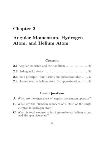
ISO 19880-1, Hydrogen Fueling Station and Vehicle Interface SafetyTechnical Report (ICHS # 116)3. Hydrogen dispensing3.1 Hydrogen Station Dispensing descriptionHydrogen fuel cell electric vehicles (FCEVs) can be fueled using dispensers thatresemble conventional fuel dispensers, with similar start, payment and even nozzleergonomics. The hydrogen and fuel cell vehicle industries are worked towards the goalof making the hydrogen fueling experience ”like today” targeting a similar fueling time(less than five minutes) and resulting vehicle range ( 500km or 300miles) such as withthe SAE J26011 and SAE J27992 standards. The station safety expectation accordingto ISO 19880-1 will also give at least an equivalent level of safety to that of fueling withconventional fuels.ISO TR 19880-1 currently assumes FCEV fueling will be done at either 35MPa or70MPa pressures. Other applications -such as forklifts- (not covered in the presentscope) may use other pressures for fueling.Figure 2 below describes an example of a fueling station dispenser, also showing thefuel cell electric vehicle compressed hydrogen storage systems (CHSS), with sensorsas well as pressure relief device(s). The CHSS has a thermally activated pressure reliefdevice(s) (TPRD) to protect against bursting of the tank if there were to be a fire.Figure 2: Station dispenser example with FCEV CHSS (from ISO 19880-1)3 Page
ISO 19880-1, Hydrogen Fueling Station and Vehicle Interface SafetyTechnical Report (ICHS # 116)On the station side, there is an automated control system, such as a ProgrammableLogic Controller (PLC), where the Fueling control including Fueling protocol, faultprocedures, etc. is programmed into the software. There is also a pressure safety-reliefvalve (PSV) to protect against over pressurization of the dispenser and vehicle. Thedispensed hydrogen temperature and pressure should be monitored by the station,along with the ambient temperature. Where appropriate, the hydrogen dispensed shouldbe metered in the station. A dispenser fueling assembly contains a breakaway, hose(s)and a dispensing nozzle, which may contain a communications receiver than canreceive communication for the vehicle (such as the SAE J2799 standard).The vehicle CHSS can be fueled after connecting the station dispenser to the vehiclereceptacle, after the startup procedure from the dispenser.3.2 Dispenser safety devicesGeneral considerationsThe dispensing control system should be capable, at any point in time during the fuelingprocess, of detecting a deviation that could be indicative of a fault that leads to ahazardous condition (e.g. over temperature and over pressure for the CHSS), andexecuting countermeasures that will mitigate the hazard.These safety measures are intended to prevent a hazardous situation in case of afailure of the dispensing control system hardware or software. The required reliability,defined through safety integrity level (SIL) or Performance Level (PL), as defined inIEC 61508, IEC 61511, IEC 62308, IEC 31010, ISO 13849-1 and/or ISO 12100 shouldbe determined through quantitative or semi-quantitative risk assessment.Countermeasures should be provided to ensure that no single or two faults result in ahazardous situation in the dispensing area. If the fueling ramp rate is determined fromthe result of a measurement by the fueling station or information communicated to thefueling station, then this function should be shown to be sufficiently reliable to effectivelyavoid an unacceptable risk of overfill, over-temperature or over-pressure in the vehicleCHSS.3.3 Dispensing safety systemsThe dispenser control should operate in conjunction with an emergency shutdownfunction that can cut off the flow of hydrogen gas to the dispenser and vehicle by closingthe automatic isolation valves. The emergency shutdown function should be availableat all times to override all other dispenser functions and operating modes to protectpeople in the dispensing area as well as equipment in the dispenser or on the vehiclebeing fueled.4 Page
ISO 19880-1, Hydrogen Fueling Station and Vehicle Interface SafetyTechnical Report (ICHS # 116)Fueling is classified by its nominal working pressure (NWP) of a full vehicle tank at 15C,such as 70 MPa. Normal fueling operation should stop at maximum 125% times thisNWP. As part of the emergency shutdown function, a means should be provided todetect a failure of the dispenser pressure sensor(s) or pressure control function, and, ifnecessary, stop fueling. Additionally, a pressure safety-relief valve should be providedto prevent over-pressurization. This over-pressure protection has two purposes:1) to protect the vehicle tank and associated hydrogen pipework2) to protect components in the dispensing systemIdeally, the dispenser components will be rated for use at the MAWP and tested at leastto ITP for their pressure class as shown in Table 1. The target is such that the PSV(s)can be set to not interfere with the normal fueling operation described above. However,if components in the dispensing system are less than the maximum allowable workingpressure shown in Table 1, then the set point of the PSV should be lowered to protectlowest rated component in the relevant pressure system. The fueling protocol shouldalso take this restriction into account and, if necessary, adjusted to minimize thelikelihood of over-pressurization of the dispenser.Table 1: ISO 19880-1 Pressure Definitions WP CITP A,B(MaximumOperatingPressure)(Maximum AllowableWorking Pressure)(Integrity TestPressure)Minimum pressureto which componentis ratedMinimum pressure towhich component istestedHighest pressurepermitted duringnormal fuellingH25H35 DH50H70 D1.00xNWP25 MPa35 MPa50 MPa70 MPa1.25xNWP31.25 MPa43.75 MPa62.5 MPa87.5 MPaTarget dispenserPSV set-point1.38xNWP34.4 MPa48.1 MPa68.8 MPa96.3 MPa1.50xNWP37.5 MPa52.5 MPa75.0 MPa105.0 MPaNotes:A. The proposed test level matches the maximum pressure expected during PSVrelieving;B. Other test pressure may be required according to national regulations;5 Page
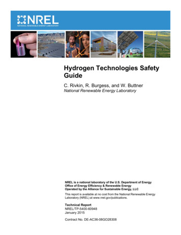
ISO 19880-1, Hydrogen Fueling Station and Vehicle Interface SafetyTechnical Report (ICHS # 116)C. Component rating needs to be valid at maximum and minimum allowablematerial temperatures;D. Pressures used for hydrogen road vehicle fueling in this document.3.4 Station Acceptance TestingISO 19880-1 give guidance for station acceptance (at factory or on site) for hydrogenproviders, inspectors and automakers. The technical report has a chapter which givesexample checklists of items which should be taken into consideration in order to accepta station for use with vehicles. See Figure 3 below.Figure 3: Example of a Station Acceptance Checklist Item from ISO 19880-1In addition, there is also technical guidance for validation of the safety functionality andperformance of hydrogen fuelling stations. Shown in Figure 4, there are primarily fourtypes of station acceptance testing related to the hydrogen fueling: The hydrogen fueling station vehicle filling safety and performance, which can bemeasured by a Hydrogen Station Test Apparatus (examples of which aredescribed in more detail in the ISO TR 19880-1).The hydrogen gas quality and particulate measurement which is measured fromtwo separate sampling devices.There is may also be a need to confirm the mass transfer according to nationalregulations through a measurement device.Figure 2 shows an example of these devices and whether these are performanceor safety relevant topics.6 Page
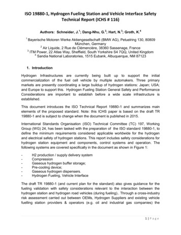
ISO 19880-1, Hydrogen Fueling Station and Vehicle Interface SafetyTechnical Report (ICHS # 116)Figure 5: Example of the Station Acceptance Testing3 needed and examples ofthe devices that can facilitate this testing, as discussed in ISO 19880-1.3.5 Hydrogen Station Test Apparatus (HSTA)In order to validate that the station operates properly before commissioning for use withFCEVs, the concept of using a hydrogen station test apparatus (HSTA3) is introduced inISO TR 19880-1. The HSTA has an onboard CHSS with a control system to simulate avehicle fueling with recording capability. Figure 6 shows an example of a HSTA inoperation with the Clean Energy Partnership in Germany.Hydrogen dispenser functional operation can be validated with an HSTA at newhydrogen fueling stations to ensure the following:A. Vehicle fueling safety parameters (including CHSS limits) are not exceededB. The performance and safety targets for fueling, including average pressure ramprate and cooling capacity, etc. are met,C. The fueling protocol, such as SAE J2601, has been properly implemented.7 Page
ISO 19880-1, Hydrogen Fueling Station and Vehicle Interface SafetyTechnical Report (ICHS # 116)Figure 6: Example of a hydrogen station test apparatus (HSTA)It is anticipated that, in most cases, the hydrogen station manufacturer would carry outdesign validation testing before the dispenser system is deployed and site acceptanceis performed. ISO TR 19880-1 lists the elements of dispenser testing that should becompleted for all stations brought into service, giving guidance on those typicallyperformed as Factory Acceptance Testing (F.A.T.) or when the station is installed onsite with Site Acceptance Testing (S.A.T).Some F.A.T. tests may be representative of multiple stations, for example whereidentical control software is used and do not need performing on each identical station.Site acceptance testing uses an HSTA to validate the “final” performance and safetyoperation just before commissioning. Table 1 below gives an overview of the FactoryAcceptance Test (F.A.T.) and site acceptance testing (S.A.T.) which should becompleted before stations are brought into service. Table 2. shows an exampleoverview of the F.A.T and S.A.T. applications from ISO TR 19880-1.8 Page
ISO 19880-1, Hydrogen Fueling Station and Vehicle Interface SafetyTechnical Report (ICHS # 116)Table 2: Hydrogen Station Dispenser function testsDispenser function TestsF.A.T.S.A.T.Co
IEC 61508, IEC 61511, IEC 62308, IEC 31010, ISO 13849-1 and/or ISO 12100 should be determined through quantitative or semi-quantitative risk assessment. Countermeasures should be provided to ensure that no single or two faults result in a hazardous situation in the dispensing area. If the fueling ramp rate is determined from the result of a measurement by the fueling station or information .File Size: 1MBPage Count: 18