Transcription
IEC 61508 Overview ReportA Summary of theIEC 61508 Standard for Functional Safety ofElectrical/Electronic/Programmable Electronic Safety-RelatedSystemsexidaSellersville, PA 18960, USA 1-215-453-1720 exidaIEC 61508 Overview Report, Version 2.0, January 2, 2006Page 1 of 29
1 Overall Document SummaryIEC 61508 is an international standard for the “functional safety” of electrical, electronic, andprogrammable electronic equipment. This standard started in the mid 1980s when theInternational Electrotechnical Committee Advisory Committee of Safety (IEC ACOS) set up atask force to consider standardization issues raised by the use of programmable electronicsystems (PES). At that time, many regulatory bodies forbade the use of any software-basedequipment in safety critical applications. Work began within IEC SC65A/Working Group 10 on astandard for PES used in safety-related systems. This group merged with Working Group 9where a standard on software safety was in progress. The combined group treated safety as asystem issue.The total IEC 61508 standard is divided into seven parts.Part 1: General requirements (required for compliance);Part 2: Requirements for electrical/electronic/programmable electronic safety-related systems(required for compliance);Part 3: Software requirements (required for compliance);Part 4: Definitions and abbreviations (supporting information)Part 5: Examples of methods for the determination of safety integrity levels (supportinginformation)Part 6: Guidelines on the application of parts 2 and 3 (supporting information)Part 7: Overview of techniques and measures (supporting information).Parts 1, 3, 4, and 5 were approved in 1998. Parts 2, 6, and 7 were approved in February 2000.The relationship between the technical requirements presented in parts 1, 2, and 3 and thesupporting information in parts 4 through 7 is shown in Figure 1. exidaIEC 61508 Overview Report, Version 2.0, January 2, 2006Page 2 of 29
PART 1Development of the overall safety requirements(scope, hazard and risk analysis)PART 2PART 5Risk based approachesto the developmentof the safety integrity requirementsPART 3Realisation phase forE/E/PE safety-relatedsystemsRealisation phase forsafety-relatedsoftwarePART 6Guidelines for theapplication of part 2 and 3PART 1PART 7Overview of techniquesand measuresInstallation and commissioning and safety validation ofE/E/PE safety-related systemsPART 1Operation and maintenance, modification and retrofit,decommissioning or disposalofE/E/PE safety-related systemsTechnicalrequirementsFigure 1: Technical requirements of IEC 61508.Although the standard was initially criticized for its “extensive” documentation requirements anduse of unproven “statistical” techniques for hardware failures, in many industries it represents agreat step forward. The standard focuses attention on risk-based safety-related system design,which should result in far more cost-effective implementation. The standard also requires theattention to detail that is vital to any safe system design. Because of these features and thelarge degree of international acceptance for a single set of documents, many consider thestandard to be major advance for the technical world.OBJECTIVES OF THE STANDARDIEC 61508 is a basic safety publication of the International Electrotechnical Commission (IEC).As such, it is an “umbrella” document covering multiple industries and applications. A primaryobjective of the standard is to help individual industries develop supplemental standards,tailored specifically to those industries based on the original 61508 standard. A secondary goalof the standard is to enable the development of E/E/PE safety-related systems where specificapplication sector standards do not already exist.Several such industry specific standards have now been developed with more on the way. IEC61511 has been written for the process industries. IEC 62061 has been written to addressmachinery safety. IEC 61513 has been written for the nuclear industry. All of these standardsbuild directly on IEC 61508 and reference it accordingly.SCOPEThe 61508 standard covers safety-related systems when one or more of such systemsincorporates mechanical/electrical/electronic/programmable electronic devices. These devicescan include anything from ball valves, solenoid valves, electrical relays and switches through tocomplex Programmable Logic Controllers (PLCs). The standard specifically covers possiblehazards created when failures of the safety functions performed by E/E/PE safety-related exidaIEC 61508 Overview Report, Version 2.0, January 2, 2006Page 3 of 29
systems occur. The overall program to insure that the safety-related E/E/PE system bringsabout a safe state when called upon to do so is defined as “functional safety.”IEC 61508 does not cover safety issues like electric shock, hazardous falls, long-term exposureto a toxic substance, etc.; these issues are covered by other standards. IEC 61508 also doesnot cover low safety E/E/PE systems where a single E/E/PE system is capable of providing thenecessary risk reduction and the required safety integrity of the E/E/PE system is less thansafety integrity level 1, i.e., the E/E/PE system is only available 90 percent of the time or less.IEC 61508 is concerned with the E/E/PE safety-related systems whose failure could affect thesafety of persons and/or the environment. However, it is recognized that the methods of IEC61508 also may be applied to business loss and asset protection cases.FUNDAMENTAL CONCEPTSThe standard is based on two fundamental concepts: the safety life cycle and safety integritylevels. The safety life cycle is defined as an engineering process that includes all of the stepsnecessary to achieve required functional safety. The safety life cycle from IEC 61508 is shownin Figure 2.!ANALYSIS"(End User / Consultant)1Concept2Overall ScopeDefinition3Hazard & RiskAnalysis4Overall SafetyRequirements5Safety RequirementsAllocationOverall PlanningOperation &Installation & 9Validation6 Maintenance 78 dsystems :E/E/PES10Safety-relatedExternal Risksystems : verall Installation& Commissioning13Overall SafetyValidation14Overall Operation &Maintenance16 (Vendor / Contractor /End User)15Overall Modification& Retrofit!OPERATION"(End User / Contractor)Figure 2: Safety life cycle from IEC 61508.It should be noted that the safety life cycle as drawn in the ISA84.01 standard (Figure 3) looksdifferent from that in IEC 61508. However, they convey the same intent and both should beviewed as similarly acceptable processes.The basic philosophy behind the safety life cycle is to develop and document a safety plan,execute that plan, document its execution (to show that the plan has been met) and continue tofollow that safety plan through to decommissioning with further appropriate documentationthroughout the life of the system. Changes along the way must similarly follow the pattern ofplanning, execution, validation, and documentation. exidaIEC 61508 Overview Report, Version 2.0, January 2, 2006Page 4 of 29
ConceptualProcess DesignDevelop SafetySpecificationHazard Analysis/Risk AssessmentSIS ConceptualDesignPre-startupSafety Review(Assessment)Develop nonSIS LayersSIS DetailedDesignSIS startup,operation,maintenance,PeriodicFunctional TestsSISRequired?NoYesEstablishOperating andMaintenanceProceduresSIS Installation,Commissioningand Pre-startupAcceptance TestANALYSISModify,Decommission?Define TargetSILREALISATIONNot Coveredby S84.01Covered IONFigure 3: Safety life cycle from ISA84.01.Safety integrity levels (SILs) are order of magnitude levels of risk reduction. There are four SILsdefined in IEC 61508. SIL1 has the lowest level of risk reduction. SIL4 has the highest level ofrisk reduction. The SIL table for “demand mode” is shown in Figure 4. The SIL table for thecontinuous mode is shown in Figure 5.Safety IntegrityLevelProbability of failureon demand, average(Low Demand mode ofoperation)Risk ReductionFactorSIL 4 10 -5 to 10 -4100000 to 10000SIL 3 10 -4 to 10 -310000 to 1000SIL 2 10 -3 to 10 -21000 to 100SIL 1 10 -2 to 10 -1100 to 10Figure 4: Safety integrity levels – demand mode. exidaIEC 61508 Overview Report, Version 2.0, January 2, 2006Page 5 of 29
Safety IntegrityLevelProbability ofdangerous failureper hour(Continuous mode of operation)SIL 4 10-9 to 10-8SIL 3 10-8 to 10-7SIL 2 10-7 to 10-6SIL 1 10-6 to 10-5Figure 5: Safety integrity levels – continuous modeThe mode differences are:Low demand mode – where the frequency of demands for operation made on a safety-relatedsystem is no greater than twice the proof test frequency;High demand or continuous mode – where the frequency of demands for operation made on asafety-related system is greater than twice the proof check frequency.Note that the proof test frequency refers to how often the safety system is completely tested andinsured to be fully operational.NOTE: The definitions in Part 4 of the IEC 61508 standard include an arbitrary one year timeinterval to distinguish between low demand and high/continuous demand. This is arbitrary andhas no relevance to probability calculation.While the continuous mode appears to be far more stringent than the demand mode, it shouldbe remembered that the units for the continuous mode are per hour. The demand mode unitsassume a time interval of roughly one year per the definition. Considering the fact that there areabout 10,000 hours in a year (actual 8,760), the modes are approximately the same in terms ofsafety metrics.Basically speaking, functional safety is achieved by properly designing a Safety InstrumentedSystem (SIS) to carry out a Safety Instrumented Function (SIF) at a reliability indicated by theSafety Integrity Level (SIL). The concepts of risk and safety integrity are further discussed inPart 5 of the standard.COMPLIANCEThe IEC 61508 standard states: “To conform to this standard it shall be demonstrated that therequirements have been satisfied to the required criteria specified (for example safety integritylevel) and therefore, for each clause or sub-clause, all the objectives have been met.”In practice, demonstration of compliance often involves listing all of the IEC 61508 requirementswith an explanation of how each requirement has been met. This applies to both productsdeveloped to meet IEC 61508 and specific application projects wishing to claim compliance. exidaIEC 61508 Overview Report, Version 2.0, January 2, 2006Page 6 of 29
Because IEC 61508 is technically only a standard and not a law, compliance is not alwayslegally required. However, in many instances, compliance is identified as best practice and thuscan be cited in liability cases. Also, many countries have incorporated IEC 61508 or large partsof the standard directly into their safety codes, so in those instances it indeed has the force oflaw. Finally, many industry and government contracts for safety equipment, systems, andservices specifically require compliance with IEC 61508. So although IEC 61508 originated as astandard, its wide acceptance has led to legally required compliance in many cases.PARTS OF THE STANDARDPart 1 covers the basic requirements of the standard and provides a detailed presentation of thesafety life cycle. This section is considered to be the most important, as it provides overallrequirements for documentation, compliance, management of functional safety, and functionalsafety assessment. Three annexes provide examples of documentation structure (Annex A), apersonnel competency evaluation (Annex B), and a bibliography (Annex C).Part 2 covers the hardware requirements for safety-related systems. Many consider this part,along with part 3, to be the key area for those developing products for the safety market. Part 2is written with respect to the entire system but many of the requirements are directly applicableto safety-related hardware product development. Part 2 covers a detailed safety life cycle forhardware as well as specific aspects of assessing functional safety for the hardware. Part 2 alsohas detailed requirements for techniques to deal with “control of failures during operation” inAnnex A (required for compliance). This annex covers hardware fault tolerance, diagnosticcapability requirements and limitations, and systematic safety integrity issues for hardware.Annex B of Part 2 (required for compliance) contains listings of “techniques and measures” for“avoidance of systematic failures during different phases of the life cycle.” This covers design,analysis, and review procedures required by the standard. Annex C of Part 2 (required forcompliance) discusses the calculation of diagnostic coverage factor (what fraction of failures areidentified by the hardware) and safe failure fraction (what fraction of failures lead to a saferather than a hazardous state). (Note: see exida technical papers for more detailed informationon these topics.)Part 3 covers the software requirements for IEC 61508. It applies to any software used in asafety-related system or software used to develop a safety-related system. This software isspecifically referred to as safety-related software. This part provides details of the softwaresafety life cycle, a process to be used when developing software. Annex A (required forcompliance) provides a listing of “techniques and measures” used for software developmentwhere different development techniques are chosen depending on the SIL level of the software.Annex B (required for compliance) has nine detailed tables of design and coding standards andanalysis and testing techniques that are to be used in the safety-related software development,depending on SIL level of the software and in some cases the choice of the development team.Part 4 contains the definitions and abbreviations used throughout all parts of the standard. Thissection is extremely useful both to those new to the standard and to those already familiar withit as a reference to the precise meanings of terms in the standard.Part 5 includes informative Annexes A through E which contain discussion and examplemethods for risk, safety integrity, tolerable risk, and SIL selection. It presents several techniquesof SIL selection including both quantitative and qualitative methods. The quantitative method inAnnex C is based on calculating the frequency of the hazardous event from failure rate data or exidaIEC 61508 Overview Report, Version 2.0, January 2, 2006Page 7 of 29
appropriate predictive methods combined with an assessment of the magnitude of theconsequence compared to the level of risk that can be tolerated in the given situation. Thequalitative risk graph and severity matrixes essentially address the same frequency andmagnitude components, only with general categories rather than numbers before comparing thesituation with the tolerable risk level.Part 6 provides guidelines on the application of Parts 2 and 3 via informative Annexes A throughE. Annex A gives a brief overview of Parts 2 and 3 as well as example flowcharts of detailedprocedures to help with implementation. Annex B provides example techniques for calculatingprobabilities of failure for the safety-related system with tables of calculation results. Equationsthat approximate various example architectures are presented, although reliability blockdiagrams are used and these can be confusing in multiple failure mode situations. Annex Cshows detailed calculation of diagnostic coverage factor based on FMEDA techniques. (Note:more information on the FMEDA technique (Failure Modes, Effects, and Diagnostics Analysis) isavailable in exida.com courses and papers.) Annex D shows a method for estimating the effectof common cause modes of failure (beta factors) in a redundant hardware architecture. Thismethod lists relevant parameters and provides a method of calculation. Annex E showsexamples applying the software integrity level tables of Part 3 for two different safety softwarecases.Part 7 contains important information for those doing product development work on equipmentto be certified per IEC 61508. Annex A addresses control of random hardware failures. Itcontains a reasonable level of detail on various methods and techniques useful for preventing ormaintaining safety in the presence of component failures. Annex B covers the avoidance ofsystematic failures through the different phases of the safety life cycle. Annex C provides areasonably detailed overview of techniques for achieving high software safety integrity. Annex Dcovers a probabilities-based approach for SIL determination of already proven software. exidaIEC 61508 Overview Report, Version 2.0, January 2, 2006Page 8 of 29
2 Part 1: General RequirementsSCOPEThe IEC 61508 standard covers safety-related systems when one or more of such systemsincorporate electrical/electronic/programmable electronic devices. This includes mechanicaldevices used in such systems, relay-based systems, inherently safe solid-state logic basedsystems, and, perhaps most importantly, programmable systems based on microcomputertechnology. The standard specifically covers possible hazards created when failures of thesafety functions performed by E/E/PE safety-related systems occur: This is known as “functionalsafety.” Functional safety is the overall program to insure that a safety-related E/E/PE systembrings about a safe state when it is called upon to do so and is different from other safetyissues. For example, IEC 61508 does not cover safety issues like electric shock, long-termexposure to toxic substances, etc. These safety issues are covered by other standards.IEC 61508 also does not cover low safety E/E/PE systems where a single E/E/PE system iscapable of providing the necessary risk reduction and the required safety integrity of the E/E/PEsystem is less than safety integrity level 1, i.e., the E/E/PE system is only reliable 90 percent ofthe time or less. IEC 61508 is concerned with the E/E/PE safety-related systems whose failurecould affect the safety of persons and/or the environment. However, it is recognized that themethods of IEC 61508 may apply to business loss and asset protection as well. Human beingsmay be considered part of a safety-related system, although specific human factor requirementsare not considered in detail in the standard. The standard also specifically avoids the concept of“fail safe” because of the high level of complexity involved with the E/E/PE systems considered.CONFORMANCEPart 1 of the standard contains the general conformance requirements. It states, “To conform tothis standard it shall be demonstrated that the requirements have been satisfied to the requiredcriteria specified (for example: safety integrity level) and therefore, for each clause or subclause, all the objectives have been met.” There is a statement that acknowledges that the“degree of rigor” (which determines if a requirement has been met) depends on a number offactors, including the nature of the potential hazard, degree of risk, etc.Often, demonstrating compliance involves listing all IEC 61508 requirements with anexplanation of how the requirement has been met. This applies to products developed to meetIEC 61508 and specific application projects wishing to claim compliance. The high level ofdocumentation for compliance is consistent with the importance of keeping detailed recordsstressed throughout the standard. (Note: exida.com has a suite of products, including a full IEC61508 requirements database, and documentation templates that can used to form a system ofcompliance meeting IEC 61508.)The language of conformance in the standard is quite precise. If an item is listed as “shall be.”or “must “, it is required for compliance. If an item is listed as “may be ” it is not specificallyrequired for compliance but clear reasoning must be shown to justify its omission.DOCUMENTATION (Clause 5)The documentation used in safety-related systems must specify the necessary information suchthat safety life cycle activities can be performed. The documentation must also provide enough exidaIEC 61508 Overview Report, Version 2.0, January 2, 2006Page 9 of 29
information so that the management of functional safety verification and assessment activitiescan effectively be accomplished. The overall reasoning is to provide proper support for the plan,do, and verify theme present throughout the safety life cycle.This translates into specific requirements for the documentation.It must:1. have sufficient information to effectively perform each phase of the safety life cycle as well asthe associated verification activities;2. have sufficient information to properly manage functional safety and support functional safetyassessment;3. be accurate and precise;4. be easy to understand;5. suit the purpose for which it was intended;6. be accessible and maintainable;7. have titles or names indicating the scope of the contents;8. have a good table of contents and index;9. have a good version control system sufficient to identify different versions of each documentand indicate revisions, amendments, reviews, and approvals.MANAGEMENT OF FUNCTIONAL SAFETY (Clause 6)Managing functional safety includes taking on various activities and responsibilities to insurethat the functional safety objectives are achieved and maintained. These activities must bedocumented, typically in a document called the functional safety management (FSM) plan. TheFSM plan should consider:1. the overall strategy and methods for achieving functional safety, including evaluationmethods and the way in which the process is communicated within the organization;2. the identification of the people, departments, and organizations that are responsible forcarrying out and reviewing the applicable overall, E/E/PES, or software safety life cycle phases(including, where relevant, licensing authorities or safety regulatory bodies);3. the safety life cycle phases to be used;4. the documentation structure;5. the measures and techniques used to meet requirements;6. the functional safety assessment activities to be performed and the safety life cycle phaseswhere they will be performed;7. the procedures for follow-up and resolution of recommendations arising from hazard and riskanalysis, functional safety assessment, verification and validation activities, etc.;8. the procedures for ensuring that personnel are competent;9. the procedures for ensuring that hazardous incidents (or near misses) are analyzed, and thatactions are taken to avoid repetition;10. the procedures for analyzing operations and maintenance performance, including periodicfunctional safety inspections and audits; the inspection frequency and level of independence ofpersonnel to perform the inspection/audit should be documented;11. the procedures for management of change.All those responsible for managing functional safety activities must be informed and aware oftheir responsibilities. Suppliers providing products or services in support of any safety life cycle exidaIEC 61508 Overview Report, Version 2.0, January 2, 2006Page 10 of 29
phase, shall deliver products or services as specified by those responsible for that phase.These suppliers also shall have an appropriate quality management system.SAFETY LIFE CYCLE REQUIREMENTS (Clause 7)The safety life cycle can be viewed as a logical “identify-assess-design-verify” closed loop(Figure 6). The intended result is the optimum design where the risk reduction provided by thesafety-related system matches the risk reduction needed by the process.IdentifyAnalyzeVerifyDesignFigure 6: Closed loop view of the safety life cycle.The safety life cycle concept came from studies done by the Health Safety Executive (HSE) inthe United Kingdom. The HSE studied accidents involving industrial control systems andclassified accident causes as shown in Figure 7.Specification 44%Changes afterCommissioning21%Design &Implementation15%Operation &Maintenance15%Installation & Commissioning6%Figure 7: Results of system failure cause study: HSE “Out of Control.”The basic aspects of the safety life cycle (shown in Figure 8) were created to address all of thecauses identified in the HSE study. exidaIEC 61508 Overview Report, Version 2.0, January 2, 2006Page 11 of 29
AccidentCausesFigure 8: Origin of the safety life cycle.SafetyManagementIEC61508Safety LifeCycleTechnicalRequirementsCompetenceof PersonsCertificationThe first part of the safety life cycle, known as the analysis portion, covers:-Concept and scope of the system or equipment under control (EUC);-Hazard and Risk Analysis to identify both hazards and the events that can lead to them,includingPreliminary Hazards and Operability (HAZOP) study,Layers of Protection Analysis (LOPA),Criticality Analysis;-Creation of overall safety requirements and identification of specific safety functions to preventthe identified hazards;-Safety requirements allocation, i.e., assigning the safety function to an E/E/PE safety-relatedsystem, an external risk reduction facility, or a safety-related system of different technology.This also includes assigning a safety integrity level (SIL) or risk reduction factor required foreach safety function.These first phases are shown in Figure 9.Figure 9: Firstportionof the overall safety life cycle.1Concept2Overall ScopeDefinition3Hazard & RiskAnalysis4Overall SafetyRequirements5Safety RequirementsAllocationThe safety life cycle continues with the realization activities as shown in Figure 10. exidaIEC 61508 Overview Report, Version 2.0, January 2, 2006Page 12 of 29
Safety -relatedSafety-relatedsystems : othersystems :10 TechnologyE/E/PES9Overall PlanningOperation &Installation &Validation6 Maintenance 78 Overall Installation& Commissioning13Overall SafetyValidationExternal ure 10: Realization activities in the overall safety life cycle.The safety systems must be designed to meet the target safety integrity levels as defined in therisk analysis phase. This requires that a probabilistic calculation be done to verify that thedesign can meet the SIL (either in demand mode or continuous mode). The system must alsoE/E/PES safety requirementsspecificationE/E/PES safetyvalidation planningE/E/PES designand developmentE/E/PES integrationE/E/PES operation andmaintenance proceduresE/E/PES safetyvalidationmeet detailed hardware and software implementation requirements given in Parts 2 and 3. Oneof the most significant is the “safe failure fraction” restriction (see Part 2). There is a moredetailed subsection of the overall life cycle called the E/E/PE life cycle, which details theactivities in box 9 above. This E/E/PE lifecycle is shown in Figure 11. These activities aredetailed in Part 2 of the standard.Figure 11: E/E/PES safety life cycle (IEC 61508, Part 2).The final operation phases of the overall safety life cycle are shown in Figure 12. exidaIEC 61508 Overview Report, Version 2.0, January 2, 2006Page 13 of 29
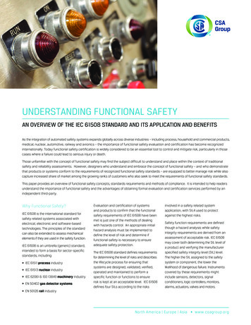
14Overall Operation &Maintenance15Overall Modification& Retrofit16 DecommissioningFigure 12: Operation and Maintenance phases of the overall safety life cycle.In summary, the safety life cycle generally lays out the different activities required to achievefunctional safety and compliance with the standard. It also should be noted that if all of the “shallbe ” and “must ” conditions are met, other safety life cycle variations also are fully compliantwith the standard.FUNCTIONAL SAFETY ASSESSMENT (Clause 8)Part 1 also describes the functional safety assessment activities required by IEC 61508. Theobjective of the assessment is to investigate and arrive at a conclusion regarding the level ofsafety achieved by the safety-related system. The process requires that one or more competentpersons be appointed to carry out a functional safety assessment. These individuals must besuitably independent of those responsible for the functional safety being assessed, dependingon the SIL and consequences involved. These requirements are shown in Tables 1 and 2.Minimum level ofConsequenceIndependenceABCDIndependent personHRHR 1NRNRIndependent departmentHR 2HR 1NR2Independent organizationHRHR(see note 2 of 8.2.12)Typical consequences could be:Consequence A - minor injury (for example temporary loss of function);Consequence B - serious permanent injury to one or more persons, deathto one person; Consequence C - death to several people;Consequence D - very many people killed.Abbreviations – HR - highly recommended, NR – not recommendedTable 1: Assessment independence level as a function of consequence.Minimum level ofIndependenceIndependent personIndependent departmentIndependent organization1HR-Safety integrity level23HR 1NRHR 2HR 1HR 24NRNRHRTable 2: Assessment independence level for E/E/PE and software life cycle activities. exidaIEC 61508 Overview Report, Version 2.0, January 2, 2006Page 14 of 29
The functional safety assessment shall include all phases of the safety life cycles. Theassessment must consider the life cycle activities carried out and the outputs obtained. Theassessment may be done in parts after each activity or group of activities. The mainrequirement is that the assessment be done before the safety-related system is needed toprotect against a hazard.The functional safety assessment must consider:1. All work done since the previous functional safety assessment;2. The plans for implementing further functional safety assessments;3. The recommendations of the previous assessments including a check to verify that thechanges have been made.The functional safety assessment activities shall be consistent and planned. The plan mustspecify the personnel who will perform the assessment, their level of independence, and theco
IEC 61508 is a basic safety publication of the International Electrotechnical Commission (IEC). As such, it is an “umbrella” document covering multiple industries and applications. A primary objective of the standard is to h

