Transcription
Introduction and Revision of IEC 61508Ron Bell OBE, BSc, CEng FIETEngineering Safety Consultants LtdCollingham House10-12 Gladstone RoadWimbledonLondon, SW19 1QTUKAbstract Over the past twenty-five years there have been a number of initiativesworldwide to develop guidelines and standards to enable the safe exploitation ofprogrammable electronic systems used for safety applications. In the context ofindustrial applications (to distinguish from aerospace and military applications) amajor initiative has been focused on IEC 61508, and other standards based on IEC61508, which have emerged as key international standards.This paper considers some of the key features of IEC 61508 (IEC 2000), whichhas now been available for over ten years, and indicates the main changes thathave been incorporated into the new Edition 2 (IEC 2010a), published in April2010.1 BackgroundThe International Electrotechnical Commission (IEC) set up a Task Group in 1985to assess the viability of developing a generic standard for programmable electronic systems to be used for safety applications, the outcome of which was the settingup of a working group to develop an holistic, systems based, approach. A workinggroup had previously been set up to deal with safety-related software. These twoworking groups collaborated on the development of an international standard thatwas to become IEC 61508 (IEC 2000).The original scope of the Task Group (programmable electronic systems usedfor safety applications) was extended to include all types of electro-technicalbased technologies (electrical, electronic and programmable electronic systems(E/E/PE systems)).Parts 1 to 7 of IEC 61508 were published during the period 1998-2000. In 2005IEC/TR 61508-0 (IEC 2005) was published. A review process to update and improve the standard was initiated in 2002 and was completed with the publicationof IEC 61508 Edition 2 (IEC 2010a) in April 2010. Engineering Safety Consultants Ltdron.bell@esc.uk.netReferences updated 9 October 2014
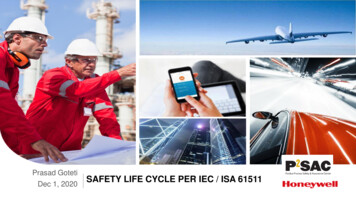
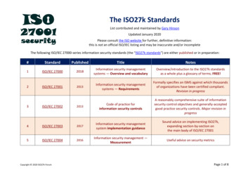
2 Structure of IEC 61508The overall title of IEC 61508 is ‘Functional safety of electrical, electronic andprogrammable electronic (E/E/PE) safety-related systems’. The Parts are aslisted in Table 1.Table 1. The Parts of IEC 61508Part Title0Functional safety and IEC 6150811General requirements2Requirements for electrical/electronic/programmable electronic safety-related systems3Software requirements4Definitions and abbreviations5Examples of methods for the determination of safety integrity levels6Guidelines on the application of parts 2 and 37Overview of techniques and measuresParts 1, 2, 3 contain all the normative requirements 2 and some informative requirements. Parts 0, 5, 6 and 7 do not contain any normative requirements.Parts 1, 2, 3 and 4 of IEC 61508 are IEC basic safety publications. One of theresponsibilities of IEC Technical Committees is, wherever practicable, to makeuse of IEC 61508, in its role as a basic publication, in the preparation of their ownsector or product standards that have E/E/PE safety-related systems within theirscope.IEC 61508 is both a stand-alone standard and can also be used as the basis forsector and product standards. In its latter role, it has been used to develop standards for the process, nuclear and railway industries and for machinery and powerdrive systems. It has influenced, and will continue to influence, the developmentof E/E/PE safety-related systems and products across all sectors. This concept isillustrated in Figure 1.The application of IEC 61508 as a standalone standard includes the use of thestandard: as a set of general requirements for E/E/PE safety-related systems where noapplication sector or product standards exist or where they are not appropriate by suppliers of E/E/PE components and subsystems for use in all sectors (e.g.hardware and software of sensors, smart actuators, programmable controllers)1 Part0 has the status of a Technical Report and is purely informative.In IEC standards a normative requirement is prefaced by ‘shall’ and if that requirement is relevant in the particular application then it is necessary to comply with the requirement. A requirement prefaced by ‘should’ is informative and can be considered as a recommendation but is notnormative in respect of compliance to relevant requirements in the standard.2
Introduction and Revision of IEC 615083 by system integrators to meet user specifications for E/E/PE safety-related systems by users to specify requirements in terms of the safety functions to be performed together with the performance requirements of those safety functions to facilitate the maintenance of the ‘as designed’ safety integrity of E/E/PEsafety-related systems to provide the technical framework for conformity assessment and certificationservices as a basis for carrying out assessments of safety lifecycle activities.Standalone: used directlyfor the applicationSector &product standardsIEC 62061: MachineryIEC 61508IEC 61511: ProcessIEC 61513: NuclearProduct (power drives)Components & elementscompliant with IEC 61508used in sector standardsFigure 1: Standalone& and sector/product standardsFig. 1. Standalone and sector/product standardsProduct or application sector international standards based on IEC 61508: are aimed at system designers, system integrators and users take account of sector-specific practice use terminology applicable in the sector to increase understanding for its intended users may specify particular constraints appropriate for the sector usually rely on the requirements of IEC 61508 for the design of subsystems.3 Scope of IEC 61508IEC 61508 is mainly concerned with E/E/PE safety-related systems whose failurecould have an impact on the safety of persons and/or the environment. However, it was recognized that the consequences of failure could have serious economicimplications and in such cases the standard could be used to specify any E/E/PEsystem used for the protection of equipment or product. This has important implications since it means that IEC 61508, which is identified with functional safety, can be
used for the specification and implementation of systems where the functional performance parameter is not safety but, for example, environmental protection or asset protection.Some of the key features of IEC 61508 are set out below. It enables the development of product and sector international standards, dealing with E/E/PE safety-related systems. This should lead to a high level ofconsistency (for example, of underlying principles, terminology etc.) both withinand across application sectors; this will have both safety and economic benefits. It provides a method for the development of the safety requirements specification necessary to achieve the required functional safety for E/E/PE safety-related systems. It uses safety integrity levels (SILs) for specifying the target level of safety integrity for the safety functions to be implemented by the E/E/PE safety-relatedsystems. It adopts a risk-based approach for the determination of the safety integritylevel requirements. It sets numerical target failure measures for E/E/PE safety-related systems thatare linked to the safety integrity levels. It sets a lower limit on the target failure measures, in a dangerous mode offailure, that can be claimed for a single E/E/PE safety-related system. ForE/E/PE safety-related systems operating in:––a low demand mode of operation, the lower limit is set at an average probability of failure of 10–5 to perform its design function on demanda high demand or continuous mode of operation, the lower limit is set at aaverage frequency of dangerous failure of 10 –9 per hour.4 Concept of functional safetySafety is defined as the freedom from unacceptable risk of physical injury or ofdamage to the health of people, either directly or indirectly, as a result of damageto property or to the environment.Functional safety is part of the overall safety that depends on a system orequipment operating correctly in response to its inputs. For example, activation ofa level switch in a tank containing a flammable liquid, which causes a valve toclose and prevent flammable liquid from entering the tank, is an instance of functional safety.
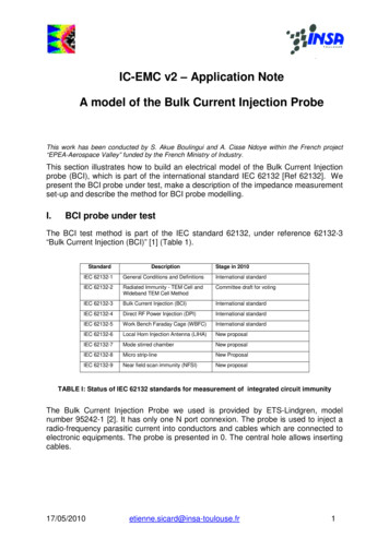
Introduction and Revision of IEC 6150855 Strategy to achieve functional safetyThe strategy for achieving functional safety is made up of the following key elements: management of functional safetytechnical requirements for relevant phases of the applicable safety lifecyclesFunctional Safety Assessment (FSA)competence of persons.IEC 61508 uses three safety lifecycles in order that all relevant phases are addressed: the Overall Safety Lifecycle (see Figure 2) the E/E/PE System Safety Lifecycle (see Figure 3) the Software Safety Lifecycle (see Figure 4).In order to deal in a systematic manner with all the activities necessary to achievethe required safety integrity for the E/E/PE safety-related systems, IEC 61508adopts the Overall Safety Lifecycle indicated in Figure 3 (IEC 61508/Edition 2shown) as the technical framework. The Overall Safety Lifecycle specified in IEC61508 should be used as a basis for claiming conformance to the standard, but adifferent Overall Safety Lifecycle can be used to that given in Figure 3, providingthe objectives and requirements of each clause of the standard are met.The overall safety lifecycle encompasses the following risk reduction model: E/E/PE safety-related systems other risk reduction measures3.The portion of the overall safety lifecycle dealing with E/E/PE safety-related systems is expanded and shown in Figure 3. This is termed the E/E/PE SystemSafety Lifecycle and forms the technical framework for IEC 61508-2. The SoftwareSafety Lifecycle is shown in Figure 4 and forms the technical framework forIEC 61508-3.It is very important to recognize that the Overall E/E/PE System Safety andSoftware Safety Lifecycle figures are simplified views of reality and as such donot show all the iterations relating to specific phases or between phases. Iteration,however, is an essential and vital part of development through the Overall E/E/PESystem Safety and Software Safety Lifecycles.Activities relating to the management of functional safety, verification andfunctional safety assessment are not shown on the Overall E/E/PE System Safetyand Software Safety Lifecycles. This has been done in order to reduce the com-3Whilst IEC 61508 provides design requirements for the achievement of functional safety forE/E/PE safety-related systems, it does not provide design requirements for ‘other risk reductionmeasures’ but does take into account the risk reduction achieved by such measures.
plexity of the safety lifecycle activities. These activities will need to be applied atthe relevant phases of the safety lifecycles.Fig. 2. Overall Safety Lifecycle from IEC 61508/Edition 2
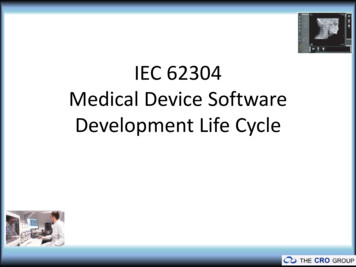
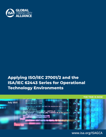
Introduction and Revision of IEC 615087Fig. 3. E/E/PE system safety lifecycle (in realisation phase) from IEC 61508/Edition 2Fig. 4. Software safety lifecycle (in realisation phase) from IEC 61508/Edition 2Evidence of the need to adopt an approach that covers all phases of the Overall Safety Lifecycle is illustrated in a study undertaken by the UK Health and Safety Executive (HSE 2003). The study analyzed a number of accidents and incidents in-
volving safety-related control systems. Figure 5 shows the primary cause of failurefor each lifecycle phase4.44.1%Specification14.7%Design &implementation5.9%Installation &commissioning14.7%Operation &maintenance20.6.1%Changes aftercommissioningFigure 2: Primary cause, by phase, ofcontrol system failuresThe analysis suggests that most control system failures may have their root causein an inadequate specification. In some cases this was because insufficient hazard analysis of the equipment under control had been carried out; in others it wasbecause the impact on the specification of a critical failure mode of the controlsystem had not been assessed.Based on the HSE study, more than 60% of failures were ‘built in’ to the safety-related system before being taken into service. Whilst the primary causes byphase will vary depending upon the sector and complexity of the application, whatis self-evident is that it is important that all phases of the lifecycle be addressed iffunctional safety is to be achieved.Fig. 5. Primary cause, by phase, of control system failures6 Essence of functional safetyA cornerstone of functional safety is the safety function. The safety function is defined as follows:‘Function to be implemented by an E/E/PE safety-related system or other risk reductionmeasures, that is intended to achieve or maintain a safe state for the equipment undercontrol in respect of a specific hazardous event.’There is a need to specify the functional safety performance requirements for eachsafety function and this is the objective of the E/E/PE system safety requirements4It is acknowledged that because of the small sample size the results of the analysis have lowstatistical significance, and therefore care needs to be taken in using these results to generalisefor all control system failures. Even so, there are many useful lessons to be learned from summaries of incidents such as these.
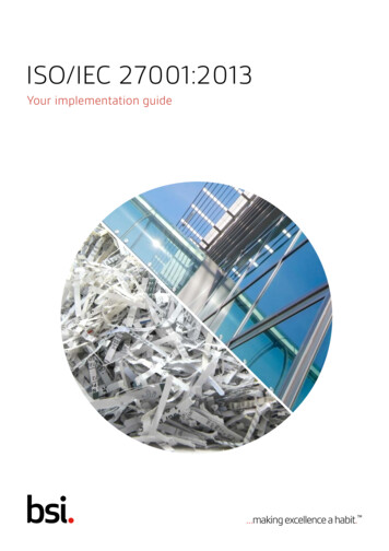
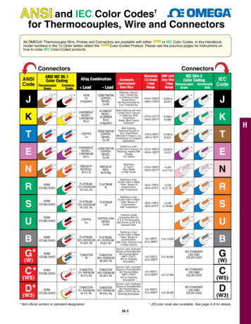
Introduction and Revision of IEC 615089specification which contains the requirements for all the safety functions beingcarried out by the E/E/PE safety-related system.If the safety function is performed the hazardous event will not take place. Thesafety function is determined from the hazard analysis. It is the safety function thatdetermines what has to be done to achieve or maintain a safe state for the equipment under control.IEC 61508 adopts a risk-based approach to the development of the specification of the required safety performance of each safety function. The safety performance is referred to as the safety integrity and is determined from the risk assessment. This is illustrated in Figure 6.SafetyfunctionSafetyintegrity ofsafetyfunction“what has to be done”.determinedfrom the hazard analysisthe “safety performance”; the likelihoodof the safety function being achieved.determined from the risk assessmentExample specification of a safety functiona.In order to prevent the rupture of pressure vessel “X”, valve“Y” should open in 2 seconds when the pressure in the vesselreaches 2.6 bar.b. The safety integrity of the safety function shall be SIL 2.Figure 3: Safety function & safety integrityof the safety functionFig. 6. Safety function and safety integrity of the safety function7 Safety-related systemsA safety-related system is a system that is capable of carrying out the variousspecified safety functions and also capable of carrying them out with the requiredsafety integrity. It is the safety integrity requirement of the safety function that setsthe safety integrity requirements for the safety-related system. A safety-relatedsystem will carry out many safety functions and must be of sufficient safety integrity to carry out the safety function with the highest safety integrity requirement(unless special measures are taken).8 Safety Integrity LevelsThe failure categories in IEC 61508 relate to failures arising from both randomhardware failures and systematic failures. The challenge to anyone designing a
complex system such as a programmable electronic system is to determine howmuch rigour/assurance/confidence is necessary for the specified safety performance level. IEC 61508 tackles this on the following basis: that it is possible to quantify the random hardware failures that is not usually possible to quantify systematic failures.IEC 61508 sets four Safety Integrity Levels (SILs). SIL 1 is the lowest and SIL 4is the highest level of safety integrity. Each SIL has a specified target failuremeasure. The target SIL of the safety function(s) determines the measures thatneed to be taken in the design of the safety-related system.Hardware Safety Integrity. This is achieved through meeting the quantified target failure measure for random failures together with meeting the ArchitecturalConstraints for the specified SIL. The latter means that specified fault tolerancerequirements (redundancy), graded to the SIL, have to be met but with a reducedfault tolerance requirement the greater the achieved Safe Failure Fraction 5.Systematic Safety Integrity. ‘Packages’ of measures are used for different systematic failure mechanisms and these are in general qualitative measures with increasing rigour, assurance and confidence the higher the SIL.Safety Integrity is made up of Hardware Safety Integrity (in relation to randomfailures) and Systematic Safety Integrity (in relation to systematic failures).The above concepts are shown in Figure 7.Quantified target failuremeasures specifiedfor each SILSafetyIntegrityLevels (SIL)4321SystematicSafety IntegrityDevelop “packages” ofspecified techniques &measures for specified SILHardwareSafety IntegrityQuantify random hardwarefailures to meet target failuremeasureArchitectural constraintsfor specified SILFigurestrategyachievea specifiedFig.4:7. DesignDesign strategyto toachievea specifiedSIL SIL5Safe Failure Fraction (SFF) is the ratio of the average failure rates of (safe failures plus dangerous detected failures) to (safe failures plus dangerous failures). The higher the ratio the greaterthe likelihood that a failure arising would be a safe failure or dangerous failure that has been detected.
Introduction and Revision of IEC 6150811The target failure measures for E/E/PE safety-related systems carrying safety functions of specified SILs are set out in Tables 2 and 3. It can be seen from these Tablesthat the SILs are linked to the target failure measures depending upon the mode ofoperation.Table 2. Safety integrity levels: target failure measures for a safety function operating in a lowdemand mode of operationSafety integrity level Average probability of a dangerous failure on demand of the safety function (PFDavg)4 10-5 to 10-43 10-4 to 10-32 10-3 to 10-21 10-2 to 10-1Table 3. Safety integrity levels: target failure measures for a safety function operating in a highdemand or continuous mode of operationSafety integrity level Probability of dangerous failure per hour (PFH)4 10-9 to 10-83 10-8 to 10-72 10-7 to 10-61 10-6 to 10-5The mode of operation is an important concept and is the way in which a safetyrelated system is intended to be used, with respect to the frequency of demandsmade upon it, which may be either: low demand mode, where the frequency of demands for operation made on asafety-related system is no greater than one per year [and no greater than twicethe proof-test frequency]6 high demand or continuous mode, where the frequency of demands for operation made on a safety-related system is greater than one per year [or greaterthan twice the proof-check frequency]6Safety functions operating in a: low demand mode of operation would typically be implemented by a protectionsystem architecture (see Figure 8) high demand mode of operation would typically be implemented by a protection system architecture or a safety-related control system architecture (see Figure 8) continuous mode of operation would typically be implemented by safetyrelated control system architecture (see Figure 8).6Criteria in square brackets not included in IEC 61508/Edition 2.
Protectionsystem architectureEUC Control SystemEquipment UnderControl(EUC)Safety-related control systemarchitectureEUC safety-relatedcontrol systemEquipment UnderControl(EUC)E/E/PE safetyrelated systemFigure 5: Safety-related system architecturesFig. 8. Safety-related systems architecturesIt should be noted that when determining the SIL, from a basis of knowing the target failure measure (which is established from the tolerable risk), the demand rate(i.e. the frequency the safety function is required to operate) is only relevant whenthe safety function is operating in a low demand mode of operation. It is not relevant when the safety function is operating in a high demand or continuous modeof operation.9 Risk based approachThe required safety integrity of the E/E/PE safety-related system, with respect to aspecific safety function, must be of such a level as to ensure that: the failure frequency of the safety-related systems is sufficiently low to prevent the hazardous event frequency exceeding that required to meet the tolerable risk, and/or the safety-related systems modify the consequences of the hazardous event tothe extent required to meet the tolerable risk.The failure frequency necessary to meet the tolerable risk, with respect to a specific safety function being carried out by the safety-related system, is determined taking into account any other risk reduction measures that are properly designed onfunctional safety criteria and properly managed throughout the life of the equipment.The determination of this failure frequency, with respect to a specified safetyfunction, allows the target failure measure to be determined and then the SIL to beestablished (from the target failure measure specified for each SIL in Table 2 orTable 3). The determination of the SIL for a specified safety function then allowsthe design process for the E/E/PE safety-related system to proceed (see Figure 7).
Introduction and Revision of IEC 615081310 Revision of IEC 61508As indicated in Section 1 of this paper, the review process to update and improvethe standard was initiated in 2002 and was completed with the publication of IEC61508 Edition 2 (IEC 2010a) in April 20107. This section provides a summary ofthe revision process.The procedure for revising an IEC standard is as follows:1. Request from National Committees their views on the standard.2. Based on the views of National Committees, prepare a Committee Draft (CD)and distribute to National Committees for their comments.3. Assess National Committee comments from the CD consultation, prepareCommittee Draft for Vote (CDV) and distribute to National Committees forvote.4. If the voting results from the CDV consultation reach the required acceptancecriteria, prepare Final Committee Draft International Standard (FDIS).5. If the voting results from the FDIS voting exercise achieve the required acceptance criteria then the standard can be prepared for publication.A key consideration during the revision process has been the need to ensure thatany changes proposed added real value to the standard and to balance any perceived benefits made to the standard against the economic costs to users of thestandard of implementing the changes.Some of the key changes are considered below. Further information on IEC61508 including Frequently Asked Question on Editions 1 and 2 can be found onthe IEC website (IEC 2010e). IEC 61508 Standards version (IEC 2010f) was also issued in April 2010 and: shows the revisions referenced to Edition 1 provides hyperlinked notes explaining the changes. This facility should proveparticularly useful for those currently using IEC 61508/Edition 1.10.1 TerminologyThere have been several important changes to the definitions and it is importantthat where changes have been made they are examined to assess the implicationssince the change may affect the interpretation as understood inIEC 61508/Edition 1.For example, the term subsystem was not a defined term inIEC 61508/Edition 1 but the usage of the term was not consistent; in IEC61508/Edition 2 this is a defined term. A key feature of the definition is that adangerous failure of the subsystem, with respect to a specified safety function, will7Parts 1-7 have been revised. Part 0 is currently planned for revision, beginning in 2010.
result in the failure of the safety function. It should also be noted that for correctusage of the term it will be necessary to have knowledge of the dangerous failuresassociated with the specified safety function. That is, there is a need to know theapplication or specify the assumptions on which the dangerous failures are basedin order to determine, for example, whether an element is also a subsystem.Other examples of key definitions that have been changed or are new includedangerous failure, safe failure, element and element safety function.10.2 Architectural constraintsThere are two possible Routes to compliance: Route 1H, based on hardware fault tolerance and safe failure fraction concepts; Route 2H, based on component reliability data from field feedback, increasedconfidence levels and hardware fault tolerance for specified safety integritylevels.There have been changes to the way in which Route 1 H is applied and togetherwith changes to the definitions of safe and dangerous failures, some differences inthe calculation of safe failure fraction may arise compared to the method specifiedin IEC 61508/Edition 1.Route 2H is a new concept for IEC 61508 and if Route 2H is selected thenclause 7.4.4.3.1 of the standard specifies the requirements as follows: a hardware fault tolerance of 2 for a specified safety function of SIL 4 unlessthe conditions in clause 7.4.4.3.2 apply a hardware fault tolerance of 1 for a specified safety function of SIL 3 unlessthe conditions in clause 7.4.4.3.2 apply a hardware fault tolerance of 1 for a specified safety function of SIL 2, operating in a high demand or continuous mode of operation, unless the conditions inclause 7.4.4.3.2 apply a hardware fault tolerance of 0 for a specified safety function of SIL 2 operating in a low demand mode of operation a hardware fault tolerance of 0 for a specified safety function of SIL 1.Clause 7.4.4.3.2 specifies, for type A elements only, if it is determined that by following the HFT requirements specified in 7.4.4.3.1, for the situation where anHFT greater than 0 is required, additional failures would be introduced and lead toa decrease in the overall safety of the EUC, then a safer alternative architecturewith reduced HFT may be implemented. In such a case this shall be justified anddocumented. The justification shall provide evidence that: following the requirements in 7.4.4.3.1 would introduce additional failures andwould lead to a decrease in overall safety of the EUC, and
Introduction and Revision of IEC 6150815 if the HFT is reduced to 0 the failure modes, in the element carrying out thesafety function, can be excluded because the associated dangerous failure ratesare very low compared to the target failure measure for the safety function under consideration. That is, the sum of the dangerous failure frequencies of allserial elements, on which fault exclusion is being claimed, should not exceed1% of the target failure measure. Furthermore the applicability of fault exclusions shall be justified considering the potential for systematic faults.A note indicates that HFT is the preferred solution to achieve the required confidence that a robust architecture has been achieved.If Route 2H is selected then reliability data used for quantifying the effect ofrandom hardware failures shall: be based on field feedbackbe collected in accordance with published standardsbe evaluated to estimate uncertainty levelsaddress the data uncertainties when calculating the target failure measureimprove the system until there is a confidence greater than 90% that the targetfailure measure has been achieved.All type B elements used in Route 2H shall have, as a minimum, a diagnostic coverage of not less than 60 %.10.3 Modes of operationThe criteria relating to when a safety function is operating in a low demand modeof operation or a high demand/continuous mode of operation have been changed:the requirements relating to the proof test frequency have been removed.10.4 Systematic safety integrityThere are three possible Routes to compliance: Route 1S, requirements for the avoidance (prevention) and requirements for thecontrol of systematic faults8 Route 2S, evidence that the equipment is ‘proven in use’ (PIU) 8 Route 3S, for pre-existing software elements only.For compliance with IEC 61508-2 it is necessary to meet the requirements ofRoute 1S or Route 2S, and for pre-existing software elements, Route 3 S.8This covers both hardware and software.
10.5 Systematic CapabilitySystematic Capability is defined as ‘a measure (expressed on a scale of SC 1 toSC 4) of the confidence that the systematic safety integrity of an element meetsthe requirements of the specified SIL, in respect of the specified element safetyfunction’.Additionally, the concept of synthesis of elements with defined Systematic Capability has been developed. This would allow two elements meeting the requirements of Systematic Capability of SC 1 (for example) to be considered as a composite element of systematic capability of SC 2 but is conditional on there being‘sufficient independence’ between the two elements.10.6 SecurityMalevolent and unauthorized actions have to be addressed during the hazard andrisk analysis. If a security threat is seen as being reasonably foreseeable, then a security threats analysis should be carried out and if security threats have been identified then a vulnerability analysis should be undertaken in order to specify security requirements.The rationale for this policy is that other IEC/ISO standards will be referencedthat address this subject in depth.10.7 E/E/PE requirements specificationThe E/E/PE requirements specification in the current Edition of IEC 61508 comprised a single specification (i.e. a single step process). Two specifications areproposed (i.e. a two step process): Step 1: develop the E/E/PE system safety requirements specification (in IEC61508-1) Step 2: develop the E/E/PE system design requirements specification (in IEC61508-2).10.8 Data communicationsThe proposed requirements have been further elaborated and now comprise theconcept of White and Black Channel architectures. Briefly:
Introduction and Revision of IEC 6150817 in White Channel architectures the entire c
use of IEC 61508, in its role as a basic publication, in the preparation of their own sector or product standards that have E/E/PE safety-related systems within their scope. IEC 61508 is both a stand-alone standard and can also be used as the basis for sector and product standard