Transcription
Prasad GotetiDec 1, 2020SAFETY LIFE CYCLE PER IEC / ISA 61511
Presenter todayPrasad Goteti, P.Eng, CFSE, TUV FS ExpertSafety Engineering ConsultantHoneywell Process SolutionsScientific Advisory Board member, Purdue Process Safety and Assurance Center (P2SAC)Member – ISA TR 84.00.07, Guidance on Fire and Gas for Process IndustriesHoneywell Confidential - 2017 by Honeywell International Inc. All rights reserved.
HoneywellAerospacePerformance MaterialsHome & BuildingTech& Tech (PMT)UOPHPSAdvancedMaterialsProjects & AutomationSolutions (PAS)Safety Engineering COEHoneywell Confidential - 2017 by Honeywell International Inc. All rights reserved.Safety & ProductivitySolutions
Agenda What is Risk ? Introduction to Functional Safety Analysis phase of the Safety Life Cycle (SLC) Realization phase of the SLC Operations and Maintenance phase of the SLC ConclusionHoneywell Confidential - 2017 by Honeywell International Inc. All rights reserved.
What is Risk ?Honeywell Confidential - 2017 by Honeywell International Inc. All rights reserved.
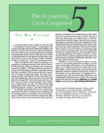
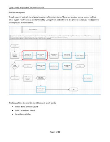
What is Risk ?Risk is defined as the combination of the frequency of occurrence of harmand the severity of that harmFREQUENCYUNACCEPTABLERISKACCEPTABLE RISKSEVERITYHoneywell Confidential - 2017 by Honeywell International Inc. All rights reserved.
The Bow Tie representationPrevention(reduces frequency)Hazardous eventMitigation(reduces severity)BPCSFire andToxic gas (SIS)ESD bleGasdetection(SIS)911Honeywell Confidential - 2017 by Honeywell International Inc. All rights reserved.
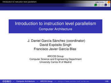
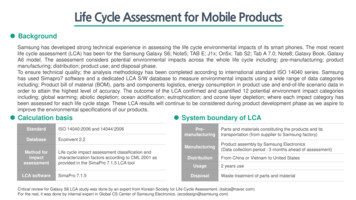
Layers of ProtectionFigure 9 of IEC 61511COMMUNITY EMERGENCY RESPONSESafety Layer(s)PLANT EMERGENCY RESPONSEMitigation:MITIGATIONe.g.Mechanical Mitigation SystemsSafety Instrumented Control SystemsSafety Instrumented Mitigation SystemsFire and GasSafety systemESD SafetysystemPREVENTIONMechanical Protection SystemProcess AlarmsOperator SupervisionSafety Instrumented Control SystemsSafety Instrumented Prevention SystemsBasic Process Control SystemsMonitoring Systems (process alarms)Operator SupervisionProcess DesignHoneywell Confidential - 2017 by Honeywell International Inc. All rights reserved.Prevention:e.g.ESD Safetysystem
What is a Safety Instrumented System (SIS)? Safety instrumented system (SIS) as per IEC61511 Instrumented system used to implement oneor more safety instrumented functions (SIF) A SIS is composed of any combination of sensor(s),logic solver(s), and final elements(s)Safety PLC or RelayFESHoneywell Confidential - 2017 by Honeywell International Inc. All rights reserved.
What are Safety Instrumented Functions (SIFs)An SIS may implement one or more safety instrumented functions(SIFs), which are designed and implemented to address a specificprocess hazard or hazardous Level switchSolenoidLogic Solver(PLC)MCCSolenoidFlowtransmitterSafety Instrumented System (SIS) withmultiple Safety Instrumented Functions (SIF)Honeywell Confidential - 2017 by Honeywell International Inc. All rights reserved.Shut-offvalveGlobevalve
What does an SIS do ?BoomMechanical Shutdown ActionTrip LevelAutomatic Shutdown Action by the SISOperator ActionHigh Alarm LevelHigh LevelBPCSprocess valueLow LevelTimeHoneywell Confidential - 2017 by Honeywell International Inc. All rights reserved.Normal behavior
Introduction to Functional SafetyHoneywell Confidential - 2017 by Honeywell International Inc. All rights reserved.
Functional Safety, part of Overall SafetyOverall SafetyOccupationalSafetyProcess SafetyFunctionalSafetyHoneywell Confidential - 2017 by Honeywell International Inc. All rights reserved.
Functional Safety standards used in the industry IEC 61508 is a standard written with an intent to help design and developproducts which are SIL rated for any industry for Electrical / Electronic /Programmable Electronic (E/EE/PE) systems. IEC 61511 and ISA84.00.01 are almost identical standards which havebeen written to help analyze, design, realize, install, commission andmaintain SIL loops for the Process industry. In the latest edition (August 2018), ISA 84.00.01 is now renamed asISA 61511 !Honeywell Confidential - 2017 by Honeywell International Inc. All rights reserved.
Generic and application sector standardsIEC62061 :MachinerySectorIEC61508Medical sectorIEC61513NuclearsectorGeneric:For use inall types of industriesIEC 61511Process sectorHoneywell Confidential - 2017 by Honeywell International Inc. All rights reserved.IEC 62279 RailwayApplications
Prescriptive and Performance based standards Prescriptive standards specify the requirement to meetthe code while performance based standards onlygive a guideline to the designer / end user. While NFPA 72 is prescriptive the IEC / ISA 61511standards are performance based.Honeywell Confidential - 2017 by Honeywell International Inc. All rights reserved.
Why Prescriptive standards do not always workIrrespective of where the mouth of the HVAC duct opens, Prescriptive standards willspecify the same number of Gas Detectors inside the buildingMouth ofHVAC ductGas detectorsMouth ofHVAC ductLocation of frequent gas leaksLocation of frequent gas leaks16Honeywell Confidential - 2017 by Honeywell International Inc. All rights reserved.
Prescriptive Standards Prescribe materials, procedures and methods, focusingin the constructive characteristics of the resulting system,usually not stating explicitly any system goals orobjectives Benefits-Easy to apply (must follow rules)Certainty about compliance (do’s or don’ts)User decisions are limitedNo commitment regarding tolerable risk levels Drawbacks– Lack of flexibility to introduce new technologies and innovations– Safety problems may be overseen if not considered by the standard– Does not give directions on safety system integrity-NFPA 85 (Boiler and Combustion Systems Hazards Code)API 556 (Instrumentation and Control Systems for Fired Heaters and Steam Generators)API RP 14C (Safety for Offshore Production Platforms)NFPA 72 (Fire Alarm / Control Systems)BLRB (Black Liquor Recovery Boiler)Honeywell Confidential - 2017 by Honeywell International Inc. All rights reserved.
Performance/Functional-Based Standards State goals and objectives to be achieved, andmethods or procedures to demonstrate that theresulting system meets the goals and objectives- Tell us how to proceed Benefits-FlexibilityThorough coverage of risks (by risk analysis methods)Maintenance and testing considered in calculationsRequires justification of decisions based on objectiveinformation Drawbacks- Needs more effort to implement- Stringent requirements to demonstrate safety integrity level- Requires user decision about risk tolerance IEC 61508 IEC 61511 ISA 84.00.01 (IEC 61511 grandfather clause)Honeywell Confidential - 2017 by Honeywell International Inc. All rights reserved.
The Safety Life Cycle as defined in the standardsConceptual ProcessDesignPerform Process HazardAnalysis & Risk AssessmentApply non-SISprotection layers to preventidentified hazards or reduceriskDevelop SafetyRequirements SpecificationEstablish Operation &Maintenance ProceduresPerform SIS ConceptualDesign, and verify it meetsthe SRSPre-startup Safety Review(Assessment)Perform SIS Design DetailNoSIS Required?SIS InstallationCommissioning and PreStartup Acceptance TestYesSIS Startup Operation,Maintenance PeriodicFunctional testingModify orDecommission SIS ?DecommissionDefine Target SILSIS ion phaseHoneywell Confidential - 2017 by Honeywell International Inc. All rights reserved.
Standard Compliance throughout SLC Analysis Phase :- Target SIL must be specified for SIF based on hazard and risk analysis- Functional requirement for SIF should be detailed Realization (Detailed Engineering) Phase :- Each SIF must meet target SIL requirements for: Random failure rate (PFDavg) Architectural constraints Development process for each component. Operation and Maintenance Phase :- Maintain SIF to the specified SIL- Any changes to the SIF should be strictly controlledIn the rest of the slides concepts from IEC 61508 and 61511 willbe discussed togetherHoneywell Confidential - 2017 by Honeywell International Inc. All rights reserved.
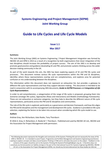
sioningplanningConcept2Overall scope definition3Hazard and RiskAnalysis4Overall safetyrequirements5Overall safetyrequirements allocation9E/E/PE system safetyrequirementsspecificationOther riskreduction measures1110Specification andRealisationE/E/PEsafety-related systemsRealisation12Overall installation andcommissioning13Overall safetyvalidationBack to appropriateoverall safety lifecyclephase1514Overall operation,maintenance and repair16Decommissioning ordisposalOverallmodificationand retrofitHoneywell Confidential - 2017 by Honeywell International Inc. All rights reserved.Functional Safety AssessmentOverall Planning1VerificationDocumentationManagement of Functional SafetyIEC 61508 - Safety Lifecycle
Strategy to achieve Functional SafetySafety life cycleSafetymanagementFailure CausesSpecification Design &implementationCompetenceOf personsInstallation &commissioning TechnicalrequirementsHoneywell Confidential - 2017 by Honeywell International Inc. All rights reserved.Operation &maintenanceChanges aftercommissioning
Question 1:Which of the following gives the best definition ofrisk?a). hazardous situation which results in harmb). potential source of harmc). combination of the probability of occurrence ofharm and the severity of that harm.d). circumstances in which a person is exposed tohazard(s).Honeywell Confidential - 2017 by Honeywell International Inc. All rights reserved.
Question 2:Which statement is true?a). Occupational safety is part of functional safety.b). Functional safety is part of process safetyc). Process and functional safety are part of occupational safetyd). None are correctHoneywell Confidential - 2017 by Honeywell International Inc. All rights reserved.
Question 3:IEC 61508 is a standard addressing:a) Burner management systemsb) Programmable electronic safety-related systemsc) Pneumatic control systemsd) Distributed control systemsHoneywell Confidential - 2017 by Honeywell International Inc. All rights reserved.
Question 4:How are IEC 61508 and IEC 61511 related to each other?a) IEC 61508 is the standard for the process industry and IEC61511 contains all the techniques that should beconsidered.b) IEC 61511 is the functional safety standard for safetyinstrumented systems for the process industry sector thatwas developed under the umbrella of the general functionalsafety standard IEC 61508.c) They are not related to each other.d) IEC 61508 describes the qualitative requirements and IEC61511 the quantitative requirements that have to be takeninto account for safety-related systems.Honeywell Confidential - 2017 by Honeywell International Inc. All rights reserved.
Question 5:The Three main phases of the Safety Life Cycle are :a) Analysis, Realization, Operation & Maintenanceb) Analysis, SIS, SRSc) Realization, Functional Safety Management, SISd) Control, Safety, Risk reductionHoneywell Confidential - 2017 by Honeywell International Inc. All rights reserved.
Analysis PhaseHoneywell Confidential - 2017 by Honeywell International Inc. All rights reserved.
The Safety Life Cycle as defined in the standardsConceptual ProcessDesignPerform Process HazardAnalysis & Risk AssessmentApply non-SISprotection layers to preventidentified hazards or reduceriskDevelop SafetyRequirements SpecificationEstablish Operation &Maintenance ProceduresPerform SIS ConceptualDesign, and verify it meetsthe SRSPre-startup Safety Review(Assessment)Perform SIS Design DetailNoSIS Required?SIS InstallationCommissioning and PreStartup Acceptance TestYesSIS Startup Operation,Maintenance PeriodicFunctional testingModify orDecommission SIS ?DecommissionDefine Target SILSIS ion phaseHoneywell Confidential - 2017 by Honeywell International Inc. All rights reserved.
Sequence of events for a Process Accident to occur Hazardo Materials Conditions(Process) Initiating Evento Technological failureo Human erroro External event Intermediate eventso Propagation factorso Containment failure Resulto Hazardous evento Loss of Containment (LOC)o ConsequencesHoneywell Confidential - 2017 by Honeywell International Inc. All rights reserved.
Costs of risk - Costs of SafeguardingCCostsAOptimumBTotal costsCosts of safeguardingCosts of riskLevel ofsafe-guardingHoneywell Confidential - 2017 by Honeywell International Inc. All rights reserved.
Risk levels based on ALARPHoneywell Confidential - 2017 by Honeywell International Inc. All rights reserved.
Example of a company’s 3 x 3 Risk matrix33Honeywell Confidential - 2017 by Honeywell International Inc. All rights reserved.
SIL Determination techniques Safety Layer Matrix (IEC 61511, Appendix – C) Calibrated Risk Graph (IEC 61511, Appendix – D/E) Layer Of Protection Analysis (LOPA) (IEC 61511, Appendix – F) Fault Tree Analysis (FTA) (IEC 61511, Appendix – B) Event Tree Analysis (ETA) (IEC 61511, Appendix – B)Let us review Risk graph and LOPA in detailHoneywell Confidential - 2017 by Honeywell International Inc. All rights reserved.
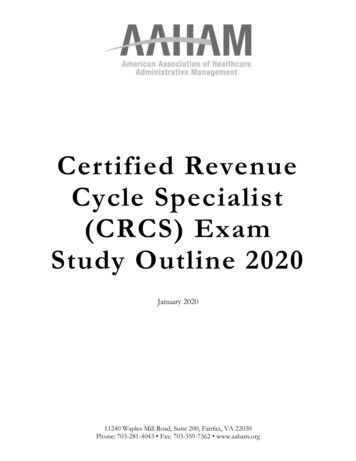
Risk graphC0:C1:C2:C3:C4:Slight damage to equipmentOne injuryOne deathSeveral deathsCatastrophic, many deathsC0C1F1F1:F2:Small probability of persons presentin the dangerous zoneHigh probability of persons presentin the dangerous zoneC2F1F2P1: Good chance to avoid the hazardP2: Hardly possible to avoid the hazardW1: Probability of hazardous event very smallW2: Probability of hazardous event smallW3: Probability of hazardous event relative ana4This calibration shows a companywith a more strict Safety PolicyHoneywell Confidential - 2017 by Honeywell International Inc. All rights reserved.
Risk Classification – ExampleC0Risk scenario , Estimated consequence one casualty. (C2) Large prob. of persons present, (F2)assume 90%. No possibility to avoid the hazard, (P2)assume 0%. Frequency of occurrence, assumed onceper 10 years. (W2)– Calculate: 1 * 0.90 * 1 * 0.1 0.09or 9 casualties per 100 year.C1F1C2P2P1F2C3P1F1F2C4Required protection: SIL 2.Honeywell Confidential - 2017 by Honeywell International Inc. All rights reserved.P2W3-W2-W1-a--1a-21a221322332433na43
Risk Graph considerations When applying the risk graph method, it is important toconsider risk requirements from the End user and anyapplicable regulatory authority. The interpretation and evaluation of each risk graphbranch should be described and documented in aclear and understandable terms to ensure consistencyin the method application. It is important that the risk graph is agreed to at asenior level within the organization taking responsibilityfor safety.Honeywell Confidential - 2017 by Honeywell International Inc. All rights reserved.
Layer Of Protection Analysis (LOPA) LOPA analyzes hazards to determine if SIFs arerequired and if so, the required Safety Integrity Level(SIL) of each SIF. Uses the Protection Layer model. For each identified hazardous event, the initiatingcauses and corresponding protective layers areevaluated LOPA does not include the protective contribution ofthe SIF.- The purpose is to determine how much RRF is needed to beprovided by the SIF to fill the Risk gap left by considering otherprotection layersHoneywell Confidential - 2017 by Honeywell International Inc. All rights reserved.
Layers of ProtectionIndependent mechanism that reduces risk by control, preventionor mitigationCommunity Emergency ResponsePlant Emergency ResponseMitigationFire & Gas DelugeRelief DevicesAutomatic SISCritical Alarms & Op responsePreventionBPCSGood Process &equipment DesignControl39Honeywell Confidential - 2017 by Honeywell International Inc. All rights reserved.
Independent Protection Layers (IPL)Protection Layer is “any independent mechanism that reducesrisk by control, prevention or mitigation”Independent Protection Layers should have: Independency between protection layersDiversity between protection layersPhysical separation between different protection layersLow common cause failures between protection layersHoneywell Confidential - 2017 by Honeywell International Inc. All rights reserved.
IPL creditsProtection layerPFDBPCS Control loop1.0 10–1Human performance (trained, nostress)1.0 10–1 to 1.0 10–2Human performance (under stress)0.5 to 1.0Operator response to alarms1.0 10–1Pressure Relief Valves1.0 x 10-2Honeywell Confidential - 2017 by Honeywell International Inc. All rights reserved.
Probability TheoryWhat is the Probability of Tossing a coin and getting ‘Heads’ ?Various possible events (2) – Heads and TailsWanted event (1) – HeadsAnswer – 1/2Honeywell Confidential - 2017 by Honeywell International Inc. All rights reserved.
Probability TheoryWhat is the Probability of rolling a dice and getting ‘4’.Various possible events (6) – 1, 2, 3, 4, 5, 6Wanted event (1) – 4Answer – 1/6Honeywell Confidential - 2017 by Honeywell International Inc. All rights reserved.
Probability TheoryWhat is the Probability of Tossing a coin and getting ‘Heads’ANDrolling a dice and getting ‘4’.Various possible events (12) – H1, H2, H3, H4, H5, H6T1, T2, T3, T4, T5, T6Wanted event (1) – H4Answer – 1/12OR1/2 x 1/6 1/12 (for INDEPENDENT events)Honeywell Confidential - 2017 by Honeywell International Inc. All rights reserved.
Case study - HazOpSP 3 BARPSV SP 4.0 BARMAWP of V-1 5 BAR Node: Vessel V-1Guideword: HIGH PRESSUREConsequence: High Pressure, possible vessel rupture & major fireCause of failure: PIC-1 (BPCS), Control valve (PCV-1) stuck openExisting Safeguards : PSV-1Additional Protection Layers : Introduce a new High pressure alarm @ 3.5 BARin PIC-1Honeywell Confidential - 2017 by Honeywell International Inc. All rights reserved.
Risk Reduction (with PSV only)From the HAZOP risk matrix for this Process, with PSV as safeguard :1. Frequency of Initiating Event (IE) – (L 3) (L 5 without any safeguards)2. Severity – Single fatality (S 2)3. Risk (with PSV as safeguard) (Box 5) (Base Risk without PSV, Box 3)LOPA TMEL (Single Fatality) :1E-05 per yearHoneywell Confidential - 2017 by Honeywell International Inc. All rights reserved.
Case study - Risk and Risk ReductionPresent Risk:1 serious injury per 10 yearsTarget Risk:1 serious injury per 100,000yResidualriskProcess riskAcceptable riskTOTAL Required RRF-10,000IncreasingriskNecessary risk reductionActual risk reductionPartial risk coveredby other technologysafety-related systemsPartial risk coveredby E/E/PEsafety-related systemsPartial risk coveredby external riskreduction facilitiesRisk reduction achieved by all safety-related systems and external riskreduction facilitiesRISK Gap - 100PSV RRF – 100Honeywell Confidential - 2017 by Honeywell International Inc. All rights reserved.Cause – PIC-1 fails
Safety Integrity LayersPFDR in 10.1AverageProbabilityto Fail onDemand9010Reliabilityof SafetyFunctionsRiskReductionFactorISAIECS84.01 61508Honeywell Confidential - 2017 by Honeywell International Inc. All rights reserved.AK87654321DIN-V19250
Risk Reduction (with PSV and SIF)From the HAZOP risk matrix for this Process, with the Two safeguards :1. Frequency of Initiating Event (IE) – (L 1)2. Severity – (S 2)3. Risk (with Two safeguards) (Box 7) (Acceptable Risk level)LOPA TMEL (Single Fatality) :1E-05 per yearHoneywell Confidential - 2017 by Honeywell International Inc. All rights reserved.
Case Study - Add a SIF (SIL2, RRF-100)PSV SP 4.0 BARPSHH-1 SP 3.75 BAR High Pressure Trip PSHH-1 added- Shuts off ESDV-1 when PT-2 detects Pressure in Vessel V-1 3.75 BAR- ESDV-1 will be a De-energized To Trip (DTT) Fail Close valve, Open when Pressure isless than 3.75 BARHoneywell Confidential - 2017 by Honeywell International Inc. All rights reserved.
Case study - With additional SIS protection layerIE - PIC-1 fails : Once every 10 years (0.1)System normalPSHH-1 fails : Once every100 demands (0.01)PSV fails : Onceevery 100demands (0.01)Probable Likelihood of Explosion PL(Loss Of Containment) x P(Ignition) 0.1 x 0.01 x 0.01 x 1 1E-05 per year ( 1E-05)Vessel V-1 ruptures and findsa source of ignition (100%)Honeywell Confidential - 2017 by Honeywell International Inc. All rights reserved.
Case study - Safety Requirement Specification (SRS) For the SIF , the Integrity (SIL) and Functionalrequirements need to be specified :- Integrity requirement for SIF PSHH-1 : to be SIL2 reliable with RRF 100- Functional requirement for SIF PAHH-1 : Shuts off ESDV-1 when PT-2 detects Pressure in Vessel V-1 3.75 BAR ESDV-1 will be a De-energized To Trip (DTT) Fail Close valve, Reset (Open) when Pressure is less than 3.75 BARWhen PT-2 fails (BadPV), start MTTR timer . If MTTR expires, Shut offESDV-1How to Reset after trip ?How to Bypass input ? .etc Honeywell Confidential - 2017 by Honeywell International Inc. All rights reserved.
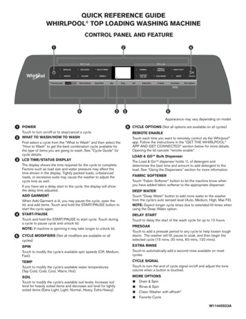
Process Safety Time (PST)PST: Time period between a failure occurring in the process (with the potential togive rise to a hazardous event) and the occurrence of the hazardous event if thesafety instrumented function is not performed.HazardousFailure ofprocess orthe basicprocesscontrolfunctionSafetyfunctionachieves safestateRequestSafetyfunction toTripDelay beforesafety functionis requestedEventSafety Function Response TimetimeInitiator ResponseTimeLogic solver ResponseTimeActuator ResponseTimeProcess Safety Time (PST)Honeywell Confidential - 2017 by Honeywell International Inc. All rights reserved.
Question 1:What is ALARPa). As less as reasonably predictedb). As low as recent problemc). As low as reasonably practicabled). None of the aboveHoneywell Confidential - 2017 by Honeywell International Inc. All rights reserved.
Question 2:What is an Initiating Event in Risk Assessmenta). The event which ends the hazardous eventb). It is the initial event before the Safety system stops workingc). It is the initial event before the Control system stops workingd). The event which starts the process that can escalate to ahazardous eventHoneywell Confidential - 2017 by Honeywell International Inc. All rights reserved.
Question 3:A SIF with a RRF of 50 is aa) SIL1 loopb) SIL2 loopc) SIL3 loopd) ‘No SIL’ loopHoneywell Confidential - 2017 by Honeywell International Inc. All rights reserved.
Question 4:What is LOPAa) Layers of Prevention Actb) Layers of Possible Actionsc) Layers of Protection Analysisd) Layers of Possible AnalysisHoneywell Confidential - 2017 by Honeywell International Inc. All rights reserved.
Question 5:What is Process Safety Timea) The time between the Initiating Event and the Hazardous eventb) The time between the Initiating Event and the BPCS responsec) The time between the Initiating Event and the SIF responsed) The time between the Initiating Event and the OperatorresponseHoneywell Confidential - 2017 by Honeywell International Inc. All rights reserved.
Realization (Detailed Engineering) PhaseHoneywell Confidential - 2017 by Honeywell International Inc. All rights reserved.
The Safety Life Cycle as defined in the standardsConceptual ProcessDesignPerform Process HazardAnalysis & Risk AssessmentApply non-SISprotection layers to preventidentified hazards or reduceriskDevelop SafetyRequirements SpecificationEstablish Operation &Maintenance ProceduresPerform SIS ConceptualDesign, and verify it meetsthe SRSPre-startup Safety Review(Assessment)Perform SIS Design DetailNoSIS Required?SIS InstallationCommissioning and PreStartup Acceptance TestYesSIS Startup Operation,Maintenance PeriodicFunctional testingModify orDecommission SIS ?DecommissionDefine Target SILSIS ion phaseHoneywell Confidential - 2017 by Honeywell International Inc. All rights reserved.
Realization phase of the Safety Life cycle With the SRS generated, the SIFs need to be engineered to meet theidentified functional and integrity requirements. As part of the realization phase:- The SIF components are specified and designed as per integrity requirements (andsome functional requirements)- The Logic solver program is written and tested as per the functional requirements inthe SRS (assuming it is a Programmable Electronic Logic Solver) The realization phase ends with Validation of the SIS, ie making surebefore system commissioning that the SIS has been designed and testedper the requirements in the SRS61Honeywell Confidential - 2017 by Honeywell International Inc. All rights reserved.
Introduction to failure rates, failure modes, PFDavg, SafeFailure Fraction62Honeywell Confidential - 2017 by Honeywell International Inc. All rights reserved.
Basic concepts Before we get into the design , let us first try to understand basic conceptslike :-Type of failuresFailure modesDiagnostic coverageSafe Failure Fraction (SFF)And more63Honeywell Confidential - 2017 by Honeywell International Inc. All rights reserved.
Types of failures: Random Failures A failure occurring at a random time, which results fromone or more of the possible degradation mechanisms.- thermal stressing- wear-out- Expressed as Failure Rate (λ) Many sources of failure rate data PFD calculation are based on Random Physical Hardware FailuresonlyHoneywell Confidential - 2017 by Honeywell International Inc. All rights reserved.
Failure rate and FIT Failure Rate (l) - Number of failures per unittime Failures/hour Failures per million hours (OREDA) Failures per billion hours (FIT’s, MIL HDBK 217) FIT : Failures in Time 5 FIT: 5 Failures per 109 hours(or 5 failures in approx. 105 years) Failure rate 1/MTTF (Mean Time To Fail)Honeywell Confidential - 2017 by Honeywell International Inc. All rights reserved.
Types of failures: Systematic failures A failure related in a deterministic way to a certaincause, which can only be eliminated by a modificationof the design or of the manufacturing process,operational procedures, documentation,or other relevant factors. Faults are produced by human error during systemdevelopment and operation- Software bugs- Wrong specification- Bad hardware design Presently there is no mathematical model to express SystematicfailuresHoneywell Confidential - 2017 by Honeywell International Inc. All rights reserved.
Failure Modes Safe failure (λS)- failure which does not have the potential to put the safety relatedsystem in a hazardous or fail to-function state- Used in PFS (Probability of Failure Spurious) calculations Dangerous failure (λD)- failure which has the potential to put the safety-related system in ahazardous or fail-to-function state- Used in PFD calculations λ (Total Failure rate) λs λDHoneywell Confidential - 2017 by Honeywell International Inc. All rights reserved.
Safe vs. Dangerous failure of a Sensing Element Pressure Transmitter in a High Pressure interlockMeasured pressure too highThe PT has failed safe,and an action is taken beforethe process is actually out of controlPressurelevelActual process conditionMeasured pressure too lowThe PT has failed dangerously,and no action is taken at time (t.)High high pressureHigh pressureAt this time moment (t) theprocess gets out of control,pressure is high high.TimeHoneywell Confidential - 2017 by Honeywell International Inc. All rights reserved.
Types of Failures Pressure Transmitter On High Pressure ( 3.75 BAR), the PT should sense and senda signal to the Logic SolverUndetectedSAFESenses Pressureas 3.75 BAR whenit is 3.75 BARDetectedSAFEBy DiagnosticsDetected By DiagnosticsDANGEROUSSenses PressureUndetectedAs 3.75 BAR when it is 3.75 BAR69Honeywell Confidential - 2017 by Honeywell International Inc. All rights reserved.
Failure modes and types for a final element Safety valve, normally open & normally energizedIn case of an out of control process, the valve has to closeUndetectedSAFEClosesspontaneouslydue to lossof energyDetected By voltagecontrolDetectedDANGEROUSStuck atopenSAFEUndetectedHoneywell Confidential - 2017 by Honeywell International Inc. All rights reserved.By valvestroke test
Diagnostic Coverage Diagnostic Coverage (DC):- Fraction of dangerous failures detected by automatic on-linediagnostic tests.- The fraction of dangerous failures is computed by using thedangerous failure rates associated with the detecteddangerous failures divided by the total rate of dangerousfailures Diagnostic Test Interval- Interval between on-line tests to detect faults in a safetyrelated system that has a specified diagnostic coverageNote – 61508 only refers to dangerous failures while 61511refers DC to both dangerous and safe failuresHoneywell Confidential - 2017 by Honeywell International Inc. All rights reserved.
Detected & Undetected Failures Safe failure (λS)- Safe detected (λSD)- Safe Undetected (λSU)SU Dangerous failure (λD)- Dangerous detected (λDD)- Dangerous Undetected (λDU)SD Diagnostics is a tool to detect failuresHoneywell Confidential - 2017 by Honeywell International Inc. All rights reserved.DUDD
Diagnostic Coverage and Failure ratesFormulae :1. λT λs λD2. λS λSU λSDTotal failure rate Sum of Safe and dangerous failureratesSafe failure rate Sum of Safe undetected and detectedfailure rates3(a) λSD DCS *λSDCS3(b) λSU (1- DCS )*λS4. λD λDU λDD Diagnostic Coverage for Safe FailuresDangerous failure rate S
How are IEC 61508 and IEC 61511 related to each other? a) IEC 61508 is the standard for the process industry and IEC 61511 contains all the techniques that should be considered. b) IEC 61511 is the functional safety standard for safety instrumented systems for the process industry sector