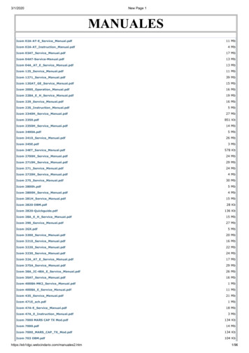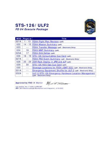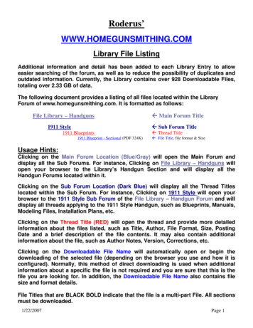
Transcription
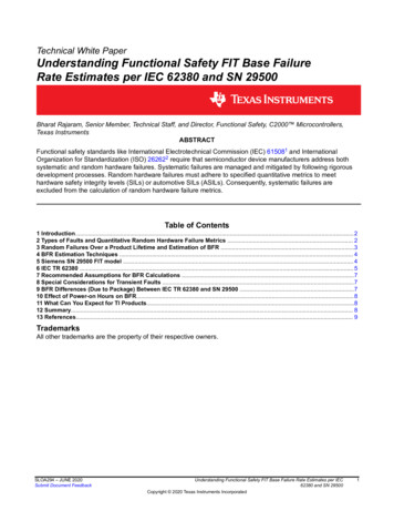
www.ti.comTechnical White PaperUnderstanding Functional Safety FIT Base FailureRate Estimates per IEC 62380 and SN 29500Bharat Rajaram, Senior Member, Technical Staff, and Director, Functional Safety, C2000 Microcontrollers,Texas InstrumentsABSTRACTFunctional safety standards like International Electrotechnical Commission (IEC) 615081 and InternationalOrganization for Standardization (ISO) 262622 require that semiconductor device manufacturers address bothsystematic and random hardware failures. Systematic failures are managed and mitigated by following rigorousdevelopment processes. Random hardware failures must adhere to specified quantitative metrics to meethardware safety integrity levels (SILs) or automotive SILs (ASILs). Consequently, systematic failures areexcluded from the calculation of random hardware failure metrics.Table of Contents1 Introduction.22 Types of Faults and Quantitative Random Hardware Failure Metrics . 23 Random Failures Over a Product Lifetime and Estimation of BFR .34 BFR Estimation Techniques . 45 Siemens SN 29500 FIT model . 46 IEC TR 62380 . 57 Recommended Assumptions for BFR Calculations .78 Special Considerations for Transient Faults .79 BFR Differences (Due to Package) Between IEC TR 62380 and SN 29500 .710 Effect of Power-on Hours on BFR.811 What Can You Expect for TI Products.812 Summary. 813 References. 9TrademarksAll other trademarks are the property of their respective owners.SLOA294 – JUNE 2020Submit Document FeedbackUnderstanding Functional Safety FIT Base Failure Rate Estimates per IEC62380 and SN 29500Copyright 2020 Texas Instruments Incorporated1
www.ti.com1 IntroductionBase failure rates (BFR) quantify the intrinsic reliability of the semiconductor component while operating undernormal environmental conditions. BFR is typically multiplied by factors such as temperature, voltage and numberof operating hours to arrive at a quantitative measure of the quality of the component.One of the primary inputs for calculating random hardware metrics (as required by functional safety standards) isthe BFR. It can be estimated by a variety of techniques. BFR estimation techniques rely on assumptions offailure modes; thus, differences in these underlying assumptions will lead to differences in BFR estimations.This paper focuses on two widely accepted techniques to estimate the BFR for semiconductor components;estimates per IEC Technical Report 623803 and SN 295004 respectively. BFR estimation is foundational tocalculate quantitative random hardware metrics, including: Safe failure fraction (SFF)Probability of failure per hour (PFH) in high-demand mode; or probability of failure per day (PFD) in lowdemand mode Single-point fault metric (SPFM) Latent fault metric (LFM) Probabilistic metric for random hardware failure (PMHF)This paper also outlines factors that influence BFR and compares and contrasts the various techniques.2 Types of Faults and Quantitative Random Hardware Failure MetricsHardware faults can be either systematic or random in nature, as shown in Figure 2-1. Systematic faults resultfrom an inadequacy in the design, development or manufacturing process and typically stem from gaps in thedevelopment process. A silicon bug is a systematic fault because it is detectable during the design verificationphase of development. For example, designing a car and specifying that it will have square wheels would beconsidered a systematic fault because the car will not work with that shape of wheel. By adhering to a rigorousdevelopment process, it is possible to manage and mitigate systematic faults – and even eliminate themcompletely – by making continuous process improvements.Figure 2-1. Overview of Systematic and Random FaultsRandom hardware faults, on the other hand, cannot be eliminated. They arise from the fact that all electronicsystems will fail eventually. Consequently, the ability to address random hardware faults is limited to detectingand possibly preventing them. In the case of automotive electrical, electronic and programmable electronicsystems, alerting drivers to a problem enables some control over the impact of random hardware faults.2Understanding Functional Safety FIT Base Failure Rate Estimates per IEC62380 and SN 29500Copyright 2020 Texas Instruments IncorporatedSLOA294 – JUNE 2020Submit Document Feedback
www.ti.comTable 2-1 and Table 2-2 list the acceptable values of random hardware failure metrics associated with each ASILor SIL value according to the requirements of ISO 26262 and IEC 61508 respectively.Table 2-1. Hardware Failure Metrics According to ISO 26262-5ASIL LevelSPFMLFMPMHF (in FIT; Failures in Time)ASIL B 90% 60% 100 FITASIL C 97% 80% 100 FITASIL D 99% 90% 10 FITTable 2-2. Hardware Failure Metrics According to IEC 61508-3SIL LevelSFFPFH (in FIT; Failures in Time)SIL 2 90% 100 FITSIL 3 99% 10 FITBoth IEC 61508 and ISO 26262 exclude systematic failures while calculating random hardware metrics.Consequently, BFR is only applicable to the failure mode distribution and calculation of random hardwaremetrics.3 Random Failures Over a Product Lifetime and Estimation of BFRFigure 3-1 shows the bathtub curve, a classic representation of random hardware faults over three key periodsof a semiconductor product’s lifetime. These are: Early life failures (also known as infant mortality): characterized by a relatively higher initial failure rate,which reduces rapidly. It is possible to further minimize early life failures by performing accelerated life tests(like burn-in or IDDQ testing) which are done as a part of Texas Instruments (TI) outgoing test in the factory.Early-life failures are primarily caused by manufacturing defects that are not effectively screened. Defects willalways occur. Developing and continuously improving effective screening is a requirement. Normal life failures: This is the region of the bath tub curve where the failure rate is relatively low andconstant. BFR estimations address this portion of the semiconductor component’s lifecycle. This failure rateis quantified in units of Failure In Time (FIT) – which is an estimate of the number of failures that could occurin a billion (109) cumulative hours of the product’s operation. Intrinsic wear-out: This is a period of the product’s lifecycle when intrinsic wear-out dominates and failuresincrease exponentially. The end of a product’s useful lifetime is specified as the time of onset of wear-out.These types of failures are caused by well-known factors such as channel-hot-carrier effects,electromigration, time-dependent dielectric breakdown and negative bias temperature instability. Functionalsafety standards such as ISO 26262 and IEC 61508 do not support the calculation of random hardwaremetrics based on a nonconstant fail rate. Consequently, a constant (but pessimistic) approximation over aproduct’s lifetime is used to estimate BFR.The system integrator has to contend with random hardware faults during normal useful life as well as the onsetof wear-out. In such circumstances, system integrators must rely on safety mechanisms, which provide a certainSLOA294 – JUNE 2020Submit Document FeedbackUnderstanding Functional Safety FIT Base Failure Rate Estimates per IEC62380 and SN 29500Copyright 2020 Texas Instruments Incorporated3
www.ti.comdiagnostic coverage and lower the risk (which is determined by severity, exposure, and controllability) to anacceptable value.Figure 3-1. The Bathtub Curve is a Classic Representation of Random Hardware Faults4 BFR Estimation TechniquesVarious techniques exist for estimating BFR: experimental, derived from field observations of incidents andcustomer returns/field failures, or an estimation based on industry-accepted reliability guides coupled with someengineering judgement.Here are a few examples of empirical techniques; however, these only account for intrinsic (silicon) failures anddisregard the contribution from silicon and package interactions: Temperature bias operating life testHigh-temperature operating life testExtended life reliability testField observations, on the other hand, require accurate and extensive record keeping, and this is not availablewhen a new product is introduced to market. Additionally, many semiconductor manufacturers do not receive allof their customer returns, making it impossible to meet the requirement for accurate and extensive records toestimate BFR.The following industry reliability guides can provide a estimation for functional safety analysis: IEC technical report (TR) 62380 and IEC 617095SN 29500, the Siemens AG standard for the reliability prediction of electronic and electromechanicalcomponentsFIDES such as a military handbook or other documentation from a credible sourceThe remainder of this paper will focus on the use of IEC TR 62380 and SN 29500 to estimate BFR.5 Siemens SN 29500 FIT modelSN 29500 uses a look-up table to find reference FIT rate and temperature for various component types such as: 4Integrated circuits (ICs)Discrete semiconductorsPassive componentsSwitches, relays, lamps, connectors, and so onUnderstanding Functional Safety FIT Base Failure Rate Estimates per IEC62380 and SN 29500Copyright 2020 Texas Instruments IncorporatedSLOA294 – JUNE 2020Submit Document Feedback
www.ti.comThe method for estimating the FIT rate of an IC starts by looking up a reference FIT rate value and reference dietemperature value from tables. The tables are separated into three types: one table for integrated circuits, asecond one for discrete semiconductors and a third one for passive components. These three tables are furtherdivided into subcategories of IC/component type and then by a range of how many transistors are in the IC ordiscrete semiconductor component.In the excerpt shown in Figure 5-1, which is from a TI functional safety FIT document for a bipolar operationalamplifier, the λ ref FIT rate is 12 FIT and the reference die temperature is 55 C. This information is sourced fromthe SN 29500 standard.Figure 5-1. TI Standard Functional Safety FIT Documentation for the SN 29500 StandardThe SN 29500 standard includes calculations for adjusting the FIT rate from the reference condition to the FITrate for the actual expected system operating conditions. Simply plug in the expected temperature profile andreference values into the equations, and calculate the component’s FIT rate in the context of the component’suse in the intended application.The following expresses the general equation for all types of components as:Application FIT rate reference FIT rate and temperature temperature factors voltage factors currentfactors % time stress factorsSystem integrators will need to refer to the information in the SN 29500 standard to derive their application’sspecific FIT rate for a TI-supplied component.6 IEC TR 62380The IEC 62380 standard is also commonly used when estimating BFR in functional safety analysis. It is areliability data handbook that outlines a universal model for predicting the reliability of electronic components,printed circuit boards (PCBs) and equipment. It was published in 2004, and subsequently obsoleted. However,the ISO 26262 standard (now in its second edition, revised in 2018) has incorporated the IEC 62380 standard aspart of its newly published Part 11 – Guidelines on Application of ISO 26262 to Semiconductors.The IEC TR 62380 IC failure rate can be modeled as sum of the die, package and electrical overstress (EOS)related failure rates, where: The die-related failure rate formula includes terms for IC type and IC technology, transistor count, thermalmission profile, junction temperature, and operating and non-operating lifetime.The package-related failure rate formula includes terms for mechanical stress caused by thermal expansions,thermal cycles, thermal mission profile, package type and package materials.The EOS failure rate formula includes terms for specific systems with an external interface and electricalenvironment.Equation 1 shows the IEC TR 62380 BFR formula (reproduced from the original standard). System integratorswill have to refer to the IEC 62380 standard to access the information required to calculate BFR.SLOA294 – JUNE 2020Submit Document FeedbackUnderstanding Functional Safety FIT Base Failure Rate Estimates per IEC62380 and SN 29500Copyright 2020 Texas Instruments Incorporated5
www.ti.com(1)Equation 2 expresses the die FIT according to IEC TR 62380 as:(2) where N is the number transistor by type, λ 1 is the transistor type scale factor, λ 2 is the technology base fitrate and α is a factor for the current year of manufacture.Equation 3 expresses the package FIT according to IEC TR 62380:(3) where πα is the difference in thermal expansion coefficients of the IC vs. the PCB and λ 3 is the packagescale factor by package type and size.Equation 4 expresses the EOS FIT according to IEC TR 62380:(4) where the default assumption is that EOS 0.If the IC application is listed in the table and the system has an external connection between the IC on the circuitboard and the outside environment, then system integrators might add EOS values as needed.Table 6-1 is a screen image from a table for an automotive mission profile according to IEC TR 62380. Accordingto this table, the overall working time for an automotive motor control application is approximately 500 hours peryear with four day time starts, two night time starts, and 30-days a year of non-use.6Understanding Functional Safety FIT Base Failure Rate Estimates per IEC62380 and SN 29500Copyright 2020 Texas Instruments IncorporatedSLOA294 – JUNE 2020Submit Document Feedback
www.ti.comTable 6-1. Mission Profiles for Representative Applications from IEC TR 62380MissionTemp. 1Profile PhasesTemp 2.t1t2t32 Night Starts4 Day LightStartsNon UsedVehicletonn1n2n2(tac)1Motor Control320.020600.015850.0230.0580.942670û7M355 1340û7M345 0.942670û7M330 1340û7M320 3010 c(tac)3Ratios on/offApplicationTypes c(tac)2Temp. 3toff c T1Cycles/ C/yearcycle T2Cycles/ C/yearcycle T3Cycles/ C/yearcycle7 Recommended Assumptions for BFR Calculations Choose only one technique and use that technique consistently. It could be:– Emperical– Based on field data State the model (Weibull or exponential) used for failure rate derived from field data– Based on reliability guide. (TI products use BFRs derived from reliability guides.)Assume a usage profile. Here are a couple of examples:– Industrial: always on 24/7 year-round until a scheduled preventive maintenance cycle– Automotive motor control: two to four starts per day, 4 hours per day of use, as in IEC TR 62380Select (and state) the confidence interval (75%, 80%, 90%) for the underlying statistics used in the estimationClearly document any scaling factors or derates that have gone into the BFR estimationAccount for non-operating time and solder-joint-based failuresAs long as all semiconductor suppliers use the same BFR estimation assumptions – or at minimum explicitlystate their assumptions – it may be possible to compare the BFRs of comparable semiconductor componentsfrom two different manufacturers.8 Special Considerations for Transient FaultsSoft errors that result from a radiation event (internal or external) that could cause random hardware failuresmust be accounted for in a BFR estimate. However, soft errors caused by electromagnetic interference orcrosstalk should not be included in BFR calculations because these are classified as systematic faults, which aremanageable by adhering to good design practices. It is possible to modulate transient faults through attributessuch as: The technology usedThe impact of the fault and when applicableStandard vs. low alpha vs. ultra-low alpha mold compounds in packagesArchitectural Vulnerability Factor (AVF) is the probability that a fault in a design structure, due to a soft error, willresult in a visible error in the final output of the function. According to ISO 26262, the BFR for soft errors shouldnot be de-rated based on AVF or safety mechanisms such as error detection and correction (EDAC) circuitry.Thus, it is best to calculate the BFR for soft errors separately for random access memory vs. logic blocks insemiconductor components.9 BFR Differences (Due to Package) Between IEC TR 62380 and SN 29500SN 29500 is deficient (vs. IEC TR 62380) in accounting for failures that are due to silicon and packageinteractions. Consequently, functional safety standards recommend that:SLOA294 – JUNE 2020Submit Document FeedbackUnderstanding Functional Safety FIT Base Failure Rate Estimates per IEC62380 and SN 29500Copyright 2020 Texas Instruments Incorporated7
www.ti.com Semiconductor component manufacturers estimate failures caused by silicon interaction with packagematerials and silicon-to-package connection points (pins)System integrators account for failures attributable to the connection points between the semiconductorcomponent and the boards (solder joints). These failures are typically analyzed at the element or systemlevel. ISO 26262 defines:– An element as a system, components (hardware or software), hardware parts, or software units; and– A system as a set of components or subsystems that relates at least a sensor, a controller and an actuatorwith one another.IEC TR 62380 accounts for both the interaction between silicon die and the lead frame/substrate and theconnection between solder joints. In contrast, the package failure rate in SN 29500 only considers die-topackage interactions, which leads to inherent optimism in BFR estimations when using SN 29500.10 Effect of Power-on Hours on BFRISO 26262 recommends applying these attributes to minimize the scaling or unjustifiable reduction of thecalculated BFR: An accurate mission profileAssessing the applicability of failure modes in the operating conditions (as specified in the mission profile)Determining the fail rate per unit (on the per-hour, day, month or year for which the system will be operated)The BFR formula in IEC TR 62380 accounts for τON and τOFF, whereas SN 29500 accounts for τW.11 What Can You Expect for TI ProductsTI has three categories of functional safety products: Functional Safety-Compliant, Functional Safety QualityManaged and Functional Safety-Capable. More information on TI's functional safety products are available here.All TI functional safety products promoted for applicability in functionally safe systems come with functionalsafety FIT rate and failure mode distribution (FMD).For our most complex products like microprocessors, microcontrollers and analog signal-chain products, systemintegrators will get a comprehensive failure modes, effects and diagnostics analysis (FMEDA) that is inclusive ofthe FMD based on a BFR estimated according to IEC TR 62380.For our least complex analog products, like low dropout oscillators, operational amplifiers and voltagesupervisors, system integrators receive a functional safety FIT, pin failure mode analysis and a FMD report thatadhere to a standard TI-wide format.Links to example reports that outline this information follow: Texas Instruments, Functional Safety FIT Rate, Failure Mode Distribution TPS7A16A-Q1Texas Instruments, Functional Safety FIT Rate, Failure Mode Distribution TPS3851-Q112 SummarySystem integrators can create safer, reliable designs faster with products, engineering expertise, and designresources from TI. Additionally, system integrators can meet the rigorous requirements of functional safetystandards, such as ISO 26262 and IEC 61508, by choosing products that come with a BFR based on either IECTR 62380 or SN 29500.8Understanding Functional Safety FIT Base Failure Rate Estimates per IEC62380 and SN 29500Copyright 2020 Texas Instruments IncorporatedSLOA294 – JUNE 2020Submit Document Feedback
www.ti.com13 References1. IEC 61508: Second edition 2010-04: Functional safety of electrical/electronic/programmable electronic safety– related systems.2. ISO 26262: Second Edition 2018-12: Road Vehicles – Functional Safety, ISO 26262, InternationalOrganization for Standardization (2018)3. IEC/TR 62380:2004(E): Reliability data handbook – Universal model for reliability prediction of electronicscomponents, PCBs and equipment4. SN 29500: Siemens Norm SN 29500/ Edition 2010-095. IEC 61709: Third Edition 2017-02: Electric components – Reliability – Reference conditions for failure ratesand stress models for conversionSLOA294 – JUNE 2020Submit Document FeedbackUnderstanding Functional Safety FIT Base Failure Rate Estimates per IEC62380 and SN 29500Copyright 2020 Texas Instruments Incorporated9
IMPORTANT NOTICE AND DISCLAIMERTI PROVIDES TECHNICAL AND RELIABILITY DATA (INCLUDING DATASHEETS), DESIGN RESOURCES (INCLUDING REFERENCEDESIGNS), APPLICATION OR OTHER DESIGN ADVICE, WEB TOOLS, SAFETY INFORMATION, AND OTHER RESOURCES “AS IS”AND WITH ALL FAULTS, AND DISCLAIMS ALL WARRANTIES, EXPRESS AND IMPLIED, INCLUDING WITHOUT LIMITATION ANYIMPLIED WARRANTIES OF MERCHANTABILITY, FITNESS FOR A PARTICULAR PURPOSE OR NON-INFRINGEMENT OF THIRDPARTY INTELLECTUAL PROPERTY RIGHTS.These resources are intended for skilled developers designing with TI products. You are solely responsible for (1) selecting the appropriateTI products for your application, (2) designing, validating and testing your application, and (3) ensuring your application meets applicablestandards, and any other safety, security, or other requirements. These resources are subject to change without notice. TI grants youpermission to use these resources only for development of an application that uses the TI products described in the resource. Otherreproduction and display of these resources is prohibited. No license is granted to any other TI intellectual property right or to any thirdparty intellectual property right. TI disclaims responsibility for, and you will fully indemnify TI and its representatives against, any claims,damages, costs, losses, and liabilities arising out of your use of these resources.TI’s products are provided subject to TI’s Terms of Sale (www.ti.com/legal/termsofsale.html) or other applicable terms available either onti.com or provided in conjunction with such TI products. TI’s provision of these resources does not expand or otherwise alter TI’s applicablewarranties or warranty disclaimers for TI products.Mailing Address: Texas Instruments, Post Office Box 655303, Dallas, Texas 75265Copyright 2020, Texas Instruments Incorporated
Table 2-2. Hardware Failure Metrics According to IEC 61508-3 SIL Level SFF PFH (in FIT; Failures in Time) SIL 2 90% 100 FIT SIL 3 99% 10 FIT Both IEC 61508 and ISO 26262 exclude syste