Transcription
EDITION 2:2020Joinery Handbook— for softwood furniture production
EDITION 2:2020Joinery Handbookproduction— for softwood furnitureThe Joinery Handbook is the result of a collaboration between Swedish Wood, theSwedish Federation of Wood and Furniture Industry (TMF), universities and colleges inSweden.The Swedish furniture industry has a huge array of options when it comes to processing solid wood for joinery and furniture production – manually but also increasinglyby automated means using CNC machines.Another key aspect is the switch from linear production to a more circular approachthat puts wood front and centre, not least due to its greater circular ecocycle (photosynthesis) and a product ecocycle that features more and more initiatives to supportcircular processes.Sustainability is important at every stage of production, and not just from an ecological perspective, but also in economic and social terms.The first chapter, about designing and drawing, has a major impact on how sustainable and circular the furniture or product will be. It is here that you can choose naturalmaterials and connection methods that enable simple dismantling for renovation ordisposal purposes. Chapter 2 provides a detailed explanation of everything to do withwood and what to think about when ordering wood for a project. In the next chapter,we go through machining, connections, hardware, surface coating and maintenanceprocedures for a long service life. Both maintenance and carefully considered planning of the furniture are important for the long-term sustainability of the product.The content of this book is aimed at smaller joinery workshops and students, but alsoat larger companies that work in the production and design of furniture and fittings,predominantly in softwood.Further information, inspiration and practical instructions regarding wood can befound on the Swedish Wood website, which is regularly updated with new knowledgeand inspiring new projects, swedishwood.com.Stockholm, September 2020Björn NordinSwedish WoodCover: Ljusterö chair, Karl Ingberg Sundsgård and José Manuel Montoya Pujol.
Joinery HandbookTable of ContentsFrom concept to design 4Gluing 871.1Drawing techniques5.1Preconditions for gluing1.2Interior products5.2Adhesive setting methods and gluing techniques1.3Classification5.3Compression equipment5.4Gluing against other surfaces975.5International standardisation10041719Ordering wood 222.1Wood as a material222.2Wood and moisture252.3Quality and range2.4Handling and storage2.5Wood and the environment879295Surface coating 1013234356.1Interior painting6.2Types of surface coating6.3Environment101103105Woodworking 37Care and maintenance 1103.1Basic cutting7.1General information3.2Mechanical processing7.2Care instructions3.3Saws3.4Planes3.5Milling machines3.6Drills3.7Sanders3.8Other machinery3.9Machine blications and websites from Swedish Wood58117616570Connections 744.1Joints4.2Furniture hardware4.3Door and window hardware747984Joinery Handbook3
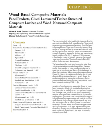
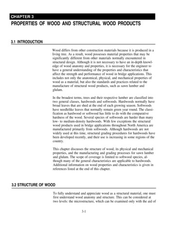
1.1 Drawing techniquesFrom concept to design1.1Drawing techniques1.2Interior 1.1.61.1.74Drawings 5Preparing and planning for manufacture 6Projection methods 7Layout of the drawing sheet 11Drawing structure 13Tolerances 16Cutting list 16171.2.1 Storage furniture 171.2.2 Tables 181.2.3 Chairs 1819It is possible to build houses, boats and furniture without drawings,as has been done throughout history. But for the customer or clientto judge what is promised against what is finally delivered, a drawinghas to be created in advance. A drawing is also required wherethe work will be carried out by someone other than the designer –when the designer and the craftsman are not the same person.Drawings for individual furniture and prototypes are usually madeby the designer or joiner and are called working or constructiondrawings. A different kind of design material is necessary for systematised series manufacture on a large scale. These are called productiondrawings and are part of the preparatory documentation. They mustbe adapted to standard dimensions that are prescribed in part byrequirements concerning the function and ergonomics of the finishedproduct and in part by the mechanical equipment used in the production process.This chapter takes a deep dive into the different kinds of drawingsthat occur in modern manufacturing. This is followed by some generaladvice and recommendations about suitable dimensions for storagefurniture, tables and chairs. The chapter concludes with a descriptionand definition of the requirements that usually apply for the variousparts of furniture in the large-scale manufacturing industry.1.1 Drawing techniquesThe process from concept to finished product requires drawings ofvarious kinds, for which there are international standards. Knowingabout these and all the technical terminology on the different partsof a drawing is important for communication with the client andeveryone else involved.Figure 1.1 Drawing of a solid wood sideboard in pine4Joinery Handbook
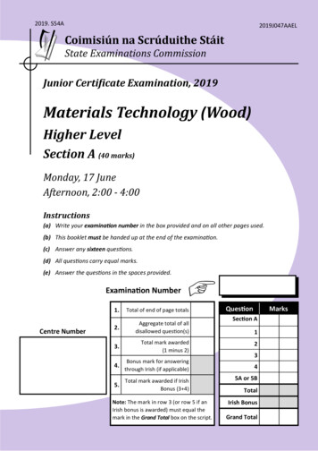
1.1 Drawing techniques1.1.1 DrawingsA picture says a thousand words. We can see this as soon as we try todescribe an object just with words. A description can end up beingextremely extensive and detailed. A drawing of the object, on the otherhand, allows us to instantly understand what it looks like and how itis constructed. Simple sketches can, for example, describe details,joints, structures and more. Drawings are therefore an importantoperational part of a manufacturing company, not least in production.When we have an idea about what we want a product to be, we usually start with a sketch.A sketch helps us to develop our ideaFurniture sketch, Malmstens, Linköping University.A77140197812R10Detailed drawings are necessary for us to get the products that we reallywant. A company’s customers have the right to receive the productsthey have been promised. It should also be possible to return withorders for the same product. The products therefore have to maintainthe same quality and appearance from one time to the next. In otherwords, for the manufacturing to operate in a way that keeps the customers happy, we have to work from the same foundation every timewe produce a new order. Drawings are therefore an important elementof the company’s quality system.Fig. 1.1, page 4 shows a type of drawing that is common in the joinery industry. Architects often use this kind of drawing and it is therefore referred to as an architectural drawing. These drawings are lifesize to a scale of 1:1. The disadvantage of a 1:1 scale drawing is that ittakes up a lot of space and is hard to handle. There are, however, various methods for reducing the size of the drawing.52655230183021SECTION A-ARIGHT1840041818FRONTA594TOPDRAWN BYDATEREVIEWED BYMB21/11 2016-Student of Furniture Design at:SCALEVIEW PLACEMENT1:105TITLE/NAMEBLUEPRINT - CONE SIDEBOARDDESIGNED BY MIKAEL BLOMGRENCARL MALMSTEN FURNITURE STUDIES DESIGN YEAR 3Linköpings UniversitetCarl Malmsten Furniture StudiesLarsbergsvägen 818139 LidingöDRAWING NREDITIONPAGE16/8Figure 1.2 Drawing of a solid pine drawerJoinery Handbook5
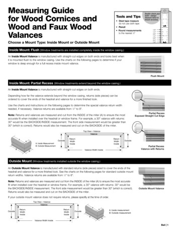
1.1 Drawing techniquesDrawings in the wood industryOn a full-scale drawing, all the dimensions can be roughly measured.Such drawings are therefore often used in the construction industry.Measuring the dimensions directly on the drawing is, however, notappropriate in the wood and joinery industry, since the measurements will not be exact. It is, for example, not possible to tell fromthe drawing how precisely tenons fit into mortices. Another difficultyis that the parts of an item of furniture are often made by several people, each of whom may read the measurements differently. In addition, furniture components may frequently be made at differenttimes and in different factories. A drawer made at a certain pointmay, for example, have to fit into a carcass that was manufacturedyears before.Figure 1.3 Screenshot from an AutoCAD programBATHROOMWMTDPrecision is importantPrecision is also crucial when manufacturing modular furniture,where you combine separate elements. Often, the furniture has newelements added after a few years. The need for precision in manufacturing in turn places high demands on the drawings. For the mostpart, you have to have a fully dimensioned drawing for every detail,i.e. a detail drawing. Precise drawings are thus a must for efficientproduction.Fig. 1.2, page 5 shows a drawing of a solid pine drawer. Milli metresare the unit of measurement used on drawings in the furniture industry. In general terms, the following basic rules apply for drawings: A drawing must be accurate, which means that it describes all threedimensions of a detail and follows the applicable projection rules. A drawing must be complete, which means that it describes allthe aspects of the product or detail in an unambiguous way. Thisincludes dimensions, surfaces, materials and so on. A drawing must be clear, which means that it is easy to read andfollows technical drawing standards. Under the technical drawingstandards, the drawing must describe a whole product or a detailof a product in its finished state.HALLLIVING ROOM1.1.2 Preparing and planningfor manufactureKITCHENCAD and CAMDINING AREABATHROOM WMTDHALLLIVING ROOMBEDROOMFigure 1.4 Example of a house designed in AutoCAD6Joinery HandbookCAD stands for Computer Aided Design. CAM stands for ComputerAided Manufacturing. A major benefit of CAD drawings is that theymake production planning easier while also being a good resourceduring the actual production process. Furthermore, a CAD drawing iseasy to change. The drawings are always on a 1:1 scale, which avoidscomplex recalculations. Printouts can then be produced in whateverscale you prefer.There are various applications, such as MechSlide, MechCAD, Pointand Genius, that have a library of symbols for screws, nuts, furniture,etc, that can be inserted into the drawing.The construction industry has software libraries of interior designfeatures that are depicted in both two and three dimensions. You can,for example, quickly build up a picture of a complete living room orkitchen.A CAD drawing is highly detailed and well defined in terms of its geo metry. This is useful when it comes to creating the programming forComputerised Numerical Control (CNC) machines, for example. Theseare numerically controlled devices for machining materials, see page 68,with their own computer that is capable of making calculations.
1.1 Drawing techniquesCNC machines can carry out numerous tasks, including drilling, milling and turning. With a CAD drawing as your starting point, you canuse CAM software to create a finished program for manufacture in aCNC machine.StandardsA standard is a set way of doing a specific task in a specific area. Itmay, for example, be that the fittings in a kitchen have to have certaincommon dimensions irrespective of the manufacturer, or that thereare common requirements regarding product properties such asstrength. Standardisation of certain products is incredibly significant.One of the first areas to be standardised was threads for various purposes, not least screws and nuts. It is easy to imagine the chaos thatwould ensue if all the manufacturers had different threads on theirscrews and nuts.A standard sets out the norms that apply and so makes productioncheaper and more uniform. Standards are set by dedicated standardisation bodies. There are a whole host of international, European andnational standards in existence. Each standard has its own specificdesignation. Standards from the International Organization forStandardization are prefixed with ISO, while the Swedish StandardsInstitute (SIS) determines Swedish Standards – SS. Sometimes astandard may be prefixed with SS-ISO, which means that an international standard has been adopted as a Swedish standard.Drawings must also be created in a standardised way. This isbecause:Pine cupboard, Mikael Blomgren, Malmstens,Linköping University. Drawings play an important role in communicating technicalinformation between different departments and people in a company and between different companies before, during and afterproduction. Drawings are also sent to the supplier and customers.Everyone who reads a standardised drawing will interpret it inthe same way. Standards mean that everyone knows what norms and rules apply.This makes creating drawings faster and more reliable.Each year SIS issues a list of current standards. If you want to stayinformed, you can subscribe to your chosen subject areas. That wayyou will receive new standards and new versions when they arepublished.1.1.3 Projection methodsA drawing describes a number of figures in three dimensions. Inorder for an object to be made according to the drawing, dimensionsmust be given for length, height, width and depth. The drawing alsoshows the object from at least three views.SS-ISO 128 contains rules on how the views should be positioned.Three methods are described: The European method (method E) The American method (method A) Method with directional arrows (the arrow method).Swedish Standards prioritise the European method and it is alsothe method that dominates in Sweden.In this material, we will only be talking about the Europeanmethod. The other methods are described in SP Wood Technology’sbook Ritteknik för möbelindustrin (Drawing technology for the furnitureindustry).Joinery Handbook7
1.1 Drawing techniquesPRIMARY VIEWSIDE VIEWPLANE VIEWPART NO.QUANTITYDRAWN BYOWNERSTITLE/NAME, DESIGNATION, MATERIAL, DIMENSIONS, ETC.REVIEWED BYAPPROVED BY – DATEAPPROVED BY – DATEGENERAL NG NO.REV. NO. TYPE OF REVISION/REVISION NOTEGENERAL SURFACEROUGHNESS, RAAPPROVED BY – DATEFigure 1.5 Drawing using the European projection method. The symbol, see figure 1.6, is placed in the title blockThe European projection methodThe European projection method (method E) is also called “the firstangle projection” or “the tipping method”, as the figures are tippedover on their side. To achieve different views, an object can be tippedinto different positions, see fig. 1.5. You begin by drawing the primaryview (A), which is the “view from the front”. The primary view mustbe the side of the object that is usually considered the front or the sidethat best describes the appearance. The primary description does notprovide sufficient description of the object. To make the drawingclear and usable, the view must be drawn from at least two sides. Inaddition to the primary view, there are further views to choose fromwhen creating a full picture of the detail. The symbol for the Europeanprojection can be seen in fig. 1.6 and it is placed in the main field onthe technical drawing template. There are other types of projectionand these are shown using other symbols in the same field.Figure 1.6 Symbol for European projectionBreak line36Object line36463Figure 1.7 Object line and break line8Joinery HandbookObject lineThe line around the section is the thickest line on the drawing. The linearound an object is the next thickest line on the drawing. Accordingto SS-ISO 128, the line must have a thickness of 0.5 mm or 0.7 mm.
1.1 Drawing techniquesBreak lineBreak lines are used to show that parts of an object have been left outof the drawing. This is particularly useful for larger objects, as youcan then draw the object on a larger scale and make any clarifications.Hidden lineThe outline of a detail that lies inside an object and therefore cannotbe seen, is drawn with a thin dashed line measuring 0.18, 0.25 or0.35 mm.Centre lineA thin dotted line of 0.18, 0.25 or 0.35 mm is used to mark the centreof a hole, for example.Fine lineWhen you want to show something in an object that is not an outline,use a fine line that measures 0.18, 0.25 or 0.35 mm.Cutting plane lineCutting plane lineDrawings are not only used to describe an object from different views.With the help of drawings, it is also possible to cut through the objectto show what the structure looks like below the visible surface and tofacilitate dimensioning. Cross-sections along a plane are the mostcommon. The cross-section divides the object into two parts, each ofwhich has a cut surface.To be clear about which of the cut surfaces on the drawing is beingreferred to, the custom is to place arrows at the thicker ends of thecutting plane line. If there are several sections on the drawing, thesection should be marked with a letter at each arrow, see fig. 1.8.Fig. 1.8 shows that the section is drawn as in a regular projection.We have used the European method here. The section is viewed fromthe left and is drawn to the right of the primary view.Section marksVarious structure and material marks are used to clarify drawings. Itis important to learn the difference between these marks and sectionmarks.Fig. 1.9 shows how end wood can be marked. The marks should onlybe used to make the manufacturer aware of the structure.There is no set standard for putting material marks on a drawing.It is therefore better to avoid using such marks. Note the material onthe item list instead, see fig. 1.19, page 13.DimensioningThe rules for dimensioning can, at first sight, seem long-winded andrather complex. The purpose is to ensure clarity and uniformity onthe production drawings/working drawings that form the basis formanufacture. Once you have procedures in place for dimensioning,you will realise the benefits of these rules. Fig. 1.10 shows how thedimension line and dimension limit line are drawn. The dimensionline should have an arrowhead at each end and the dimension limitline should be drawn around 2 mm beyond the dimension line.The distance between the outline and first dimension line, where youmay sometimes wish to place text, should be 12 mm, if the text heightis 3.5 mm. The distance between two dimension lines is 10 mm forthe same text height of 3.5 mm.ACut surfaceAFigure 1.8Cutting plane lineFigure 1.9Cut surfaceDimension lineDimension limit line350Figure 1.10 DimensioningJoinery Handbook9
1.1 Drawing techniquesDimension arrows according to Swedish StandardsSwedish Standards have four different variants of the arrowhead, seefig. 1.11. The angle of the point is between 15 and 90 . The furnitureindustry and furniture workshops mainly use the solid arrowhead,see fig. 1.11 a). As a rule, only one type of arrow should be used onthe same drawing. The aim is always to make the drawing as consistent and uniform as possible. The dimension should be placed abovethe dimension line, preferably centred along the line. The dimensionshould be readable from the bottom or the right of the drawing.The dimension of an object must only be given in one view andshould not be repeated if it occurs in multiple views on the drawing.Dimensions that belong together, such as dimensions used for setting up an operation, should be as close as possible to each other onthe drawing. They should not be spread across more views than isabsolutely necessary.a)Figure 1.11 Dimension arrowsDimensioning arcs or chamfersFig. 1.12 demonstrates different ways of showing the dimensions ofarcs and chamfers. The most common way to give the dimension ofa radius is to write it in the text box. Example: Object lines shouldhave a radius of approx. 2 mm.R32xR3 Radius 3 mmTwo radiuseswith Radius 345 4x45 4Two ways of dimensioning 45 chamfer4 mm from cornerFigure 1.12 Dimensioning arc or chamferBaseline dimensioningDimensioning from a zero point is called baseline dimensioning seefig. 1.14, and it is considered a more accurate method than chaindimensioning see fig. 1.13. The disadvantage of baseline dimensioningis that it takes up a lot of space on the drawing. Baseline dimensioning can be simplified to occupy less space, but that creates a greaterrisk of misunderstanding.Simplified baseline dimensioningWhen dimensioning a hole or a chamfer, for example, there may notalways be room between the dimension limit lines for a clear measurement. In this case measurements should be positioned as shownin fig. 1.15 page 11.As a general rule, measurements should be placed outside the object.Dimension lines and dimension limit lines that cross each other orother lines should be avoided. However, if it makes the drawingclearer, measurements can be placed inside the diagram.Outlines and centre lines must not be used as dimension lines. Inexceptional cases, they may be used as dimension limit lines, but thisshould preferably be avoided.24420323232323232322032Figure 1.13 Chain dimensioning84116148180212244Figure 1.14 Baseline dimensioning10Joinery Handbook
1.1 Drawing techniques552315203523 1223 83510251045Figure 1.15 Simplified baseline dimensioningFigure 1.16 Positioning of measurementsIn fig. 1.16 the measurement is on the actual drawing, between the twoholes where there is no other hole on the drawing. If there is a risk ofthe dimension limit line crossing other lines on the drawing, however,placing the measurement outside the diagram is correct.1.1.4 Layout of the drawing sheetTo ensure that drawings are clear and easy to read, there is also auniform layout for the information needed on drawings. The layoutconvention relates to the positioning of the title block, revision blockand item list, plus the type of information that should be placed inthese fields.FrameEdgeMarginDrawing areaItem listTitle blockRevision blockPART NO.QUANTITY TITLE/NAME, DESIGNATION, MATERIAL, DIMENSIONS, ETC.DRAWN BYOWNERSREVIEWED BYAPPROVED BY – DATEDRAWING NO.REV. NO. TYPE OF REVISION/REVISION NOTEAPPROVED BY – DATEGENERAL TOLERANCEGENERAL SURFACEROUGHNESS, RAPROJECTIONSCALEEDITIONPAGETITLE/NAMEAPPROVED BY – DATEFigure 1.17 Layout of the drawing sheetJoinery Handbook11
1.1 Drawing techniquesTitle blockThe title block is always placed in the bottom right-hand corner ofthe drawing field, together with the item list and sometimes the revision block. This is true whether the drawing is in portrait or landscape format.The title block contains the title and designation of the drawingplus a range of other information, such as the number and scale ofthe drawing, who made the drawing and the owner of the drawing.Fig. 1.18 below shows a title block that follows standard SS 3149,adapted for the wood industry.The following details must be provided in the title block: Owner . The title is the name of the drawing (sub-assembly). The designationrefers to what the drawing represents (carcass). If the drawn detailbelongs to a larger part, you can also include the name of the largerpart in the title . The number of the drawing according to the company’s proceduresfor documentation . Signatures of the people who drew/designed, reviewed and approvedthe drawing. The company’s procedures for documentation management state who is authorised to carry out these various tasks . The main scale of the drawing . Symbol showing which projection method has been used .General surface roughness. Other general dimensional tolerancesAare stated in plain text . A-A Issue, expressed as a number .350 Where drawings have multiple sheets, both the sheet number andtotal number of sheets should be stated, for example 1/4 or 1(4) .Pine stool, Hemmo Honkonen, Malmstens,Linköping University.1000Revision block510Sometimes drawings need to be revised over the course of the job. Allcorrections to the drawing must be meticulously noted, giving detailsof what the change related to and when it was carried out. In A4 format, the revision block should be placed in the top right-hand cornerof the drawing. In large formats, it should be placed to the left ofthe title block . When you make a change, you can sometimes createa new issue of the drawing at the same time. In this case, the designation used for the revision can also be used to name the new issue.On the drawing, the detail that has been changed is marked witha revision symbol in the form of a triangle.There are two ways to list the changes in the revision block. YouAcan either briefly describe the change in the revision block or statea memo number that refers to a revision memo. It is essential thateveryone concerned – for example product developers and draftsmen– is informed about the changes that have been made over the courseof the job. Deficiencies in the information can cost the companyBASEdearly. EveryoneBACKin the company should therefore regularly reviewtheir proceduresTRACKregarding internal and external information.SHELFSIDEPART NO. QUANTITYTITLE/NAME, DESIGNATION, MATERIAL, DIMENSIONS, ETC.DRAWN BYREVIEWED BY44APPROVED BY – DATEFigure 1.18 Title block and revision block12Joinery Handbook7PROJECTION6SCALEFRAMEWORK, ITEM LIST10APPROVED BY – DATE4GENERAL SURFACEROUGHNESS, RATITLE/NAMEOWNERSREV. NO. TYPE OF REVISION/REVISION NOTEARTICLE NO. - REFERENCEGENERAL TOLERANCE1DRAWING NO.523EDITION8PAGE9
1.1 Drawing techniquesABASEBACKTRACKSHELFSIDEPARTITIONTOPPART NO. QUANTITYTITLE/NAME, DESIGNATION, MATERIAL, DIMENSIONS, ETC.DRAWN BYREVIEWED BYOWNERSAPPROVED BY – DATEARTICLE NO. - REFERENCEGENERAL TOLERANCEGENERAL SURFACEROUGHNESS, RAPROJECTIONSCALEEDITIONPAGETITLE/NAMEFRAMEWORK, ITEM LISTDRAWING NO.APPROVED BY – DATEFigure 1.19 Item listItem listOn drawings of composite objects, additional information aboutdetails and materials is given in an item list. The item list is the samelength as the drawing’s title block and is placed above that field, seefig. 1.19.ScalesThe format of the drawing can be reduced using symmetry and breaklines. You can also vary the size of the drawing by using differentscales, usually as shown in table 1.1.It is of course not always possible to use drawings in natural size,as they soon become too big and unwieldy. It is therefore useful tobe able to create drawings on a reduced scale. This applies to bothassembly drawings and detail drawings.Sometimes it may be necessary to make the dimensioning clearer,to avoid misreadings. This can be achieved by enlarging a particulardetail on part of the drawing, for example, see fig. 1.20. TheApart beingenlarged should be circled with a solid line. Then you label the areawith a capital A, B, C etc – above the circle.The enlarged view of the part is positioned elsewhere on the drawing, where it is delimited with a circle or break line. State the scalein brackets next to the capital letter. A scale of 1:1 is often used foran enlarged view. Where there are multiple enlarged views, they areplaced in alphabetical order.Table 1.1 Scale tableScaleEnlarged2:15:11:21:510:1Full scale1:1ReducedA1:10A (1:1)A (1:1)Figure 1.20 Part enlargement1.1.5 Drawing structureIn order to get a good overview of the project and the various drawings, you should settle on a drawing structure. Fig. 1.21 illustrateswhat a drawing structure might look like.Sometimes, there may be no need to produce a sub-assembly drawing, in which case you can skip that step and go straight to the detaildrawing.General arrangement drawingThe general arrangement drawing describes what the finished productwill look like and the overall dimensions. In order to refer to subassembly drawings or detail drawings, they must be given a number,see fig. 1.22, page 14. The number is placed in a circle that is drawnwith a fine solid line. A reference line is then drawn from the circleto the detail. If possible, the circles should be placed together, andGeneral arrangement drawingSub-assembly drawingSub-assembly taildrawingFigure 1.21 Drawing structure for preparatorydocumentationJoinery Handbook13
1.1 Drawing techniquesarranged in a vertical or horizontal line. The number should beentered in the item list and should refer to a drawing number: 100 general arrangement drawing 110 sub-assembly drawing 111 detail drawing.Sub-assembly drawingIf it is not possible to describe the function of the product or the detailsin the GA drawing, the drawing will have to be divided up intosub-assembly drawings. If the function of the detail is described inthe sub-assembly drawing, it is also drawn in a simplified form onthe GA drawing.Both the GA drawing and the sub-assembly drawings should featurereferences to detail drawings. These are noted in the item list as set outin fig. 1.23, page 15.Detail drawing612618R15As the name suggests, a detail drawing describes just one detail.The drawing should contain all the information required aboutthe detail’s function and its finished dimensions, see fig. 1.24, page 15.There is no requirement to be able to read the detail’s placement inthe product from the detail drawing. When creating a detail drawing,it is necessary to put yourself in the manufacturer’s shoes and laythe drawing out in such a way that the manufacturer can easily readthe clearance measurements and other information that is vital forthe production. There is no room for 20FRONTRIGHTFRONT AND SIDEDRAWN BYDATEREVIEWED BYMB21/11 2016-Student of Furniture Design at:SCALEVIEW PLACEMENT1:10TITLE/NAMEBLUEPRINT - CONE SIDEBOARDDESIGNED BY MIKAEL BLOMGRENCARL MALMSTEN FURNITURE STUDIES DESIGN YEAR 3Linköpings UniversitetCarl Malmsten Furniture StudiesLarsbergsvägen 818139 LidingöFigure 1.22 General arrangement drawing14Joinery HandbookDRAWING NREDITIONPAGE10012/8
1.1 Drawing TITIONTOPPART NO.QUANTITYDRAWN BYTITLE/NAME, DESIGNATION, MATERIAL, DIMENSIONS, ETC.REVIEWED BYAPPROVED BY – DATEARTICLE NO. - REFERENCEGENERAL TOLERANCEGENERAL SURFACEROUGHNESS, RASCALEEDITIONPAGEFRAMEWORK, ITEM LISTDRAWING NO.REV. NO. TYPE OF REVISION/REVISION NOTEPROJECTIONTITLE/NAMEOWNERSAPPROVED BY – DATEFigure 1.23 Sub-assembly drawingA0R1DETAIL ASCALE 1 : 1HANDLE CUTDRAWN BYDATEREVIEWED BYMB21/11 2016-Student of Furniture Design at:SCALEVIEW PLACEMENT1:10TITLE/NAMEBLUEPRIN
Joinery Handbook 3 Table of Contents From concept to design 4 1.1 Drawing techniques 4 1.2 Interior products 17 1.3 Classification 19 Ordering wood 22 2.1 Wood as a material 22 2.2 Wood and moisture 25 2.3 Quality and range 32 2.4 Handling and storage 34 2.5