Transcription
ENCYCLOPEDIA OF GROUNDINGSECTION 8Personal Protective Equipment8Phone: 573-682-5521Fax: 573-682-8714210 North Allen St.Centralia, MO 65240, USAhubbellpowersystems.com Copyright 2022 Hubbell Incorporated. Bulletin 07-0801
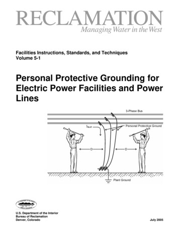
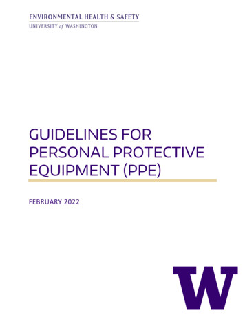
PERSONAL PROTECTIVE EQUIPMENTHubbell Power Systems offers a wide variety ofCHANCE personal protective grounding equipment. Most clamps and assemblies are tested andrated per ASTM F855 and/or IEC 61230. Some itemsare designed for special applications and are notcovered by a standard. Where appropriate, catalog literature indicates conformance to an ASTMgrade or IEC rating.In the past, protective-grounding equipment wasconsidered to be only a chain thrown over the lineand grounded. Later it became a piece of cablewith a clamp on each end. While that is basicallytrue, the selection and correct use has addedmore complexity. Early versions of the governingstandard specified current levels that ensured thecable would not fuse during operation. There wasno mention of the voltage drop across the manduring the time current was flowing. This remainstrue today. Because this is such a key factor inprotecting workers, it has been addressed morecompletely in other sections.ClampsCHANCE grounding clamps come in a varietyof styles, sizes and ratings. Included are C-typeclamps in Figure 8-1, also Snap-On (Duckbill-type)in Figure 8-2 and Flat-Face in Figure 8-3, All-Anglein Figure 8-4, and Ball-and-Socket styles in Figure 8-5. Clamps are designed for mounting withinsulated hot sticks and some by hand. Others arepermanently mounted onto the end of insulatedsticks. A complete line of accessories such as polemount cluster bars, fully assembled groundingsets, underground distribution transformer andswitch grounding items, cutout clamps and setsfor substation use complement the CHANCE lineof clamps.Each clamp has specific applications for which itwas designed. C-type clamps are typically usedon round bus or stranded conductor; the Flat-Faceclamp is used on flat bus or tower legs or braces;the All-Angle clamp is a popular style where different conductor approach directions are required.Personal protective grounding assemblies consistof clamps, ferrules and interconnecting cable. Eachcomponent should be selected to complement theothers to achieve the desired level of protection.For example, clamps and ferrules must carry thesame or higher current rating than the cable thatthey are used with in an assembly. The selectionof personal protective grounding equipment rating and style is the choice of the user, importantcriteria being its electrical and mechanical ratings.Equipment must be sized to provide the necessaryworker protection if called upon to do so. It mustbe capable of carrying the full fault current withits degree of asymmetry and duration, and survivethe resulting mechanical forces and heat. As available fault current levels increase, the demands onthe equipment increases, not proportionally, butas the square of the current. That is, if the currentdoubles, the mechanical force quadruples and thecable heating increases. Additionally, high levels ofasymmetry significantly increase the mechanicalforces.8-2ENCYCLOPEDIA OF GROUNDING
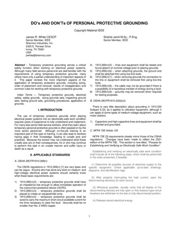
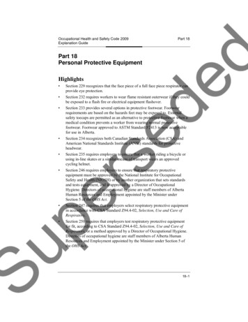
G3369C6002256G18102G36221Duckbill ClampsFigure 8-2C-ClampsFigure 8-1A unique development by Chance was the Balland-Socket set. This consists of an electricalgrade copper rod, threaded on one end and witha spherical ball machined on the other. The matingclamp has an opening shaped like a keyhole. Thelarger opening accepts the ball and the smalleropening captures the rod. Because the clamp isfree to move on the ball, it minimizes stress on thecable by allowing the cable to hang in a normalposition. Then, tightening the eyescrew capturesthe ball. A rubber cover may be used to protectthe ball stud when it is not in use.G33632C6001735Flat-Face ClampsFigure 8-3T6001693C6002102C6002100G42291SJAll-Angle ClampsFigure 8-4CHANCE LINEMAN GRADE TOOLS Ball & Socket SetFigure 8-58-3
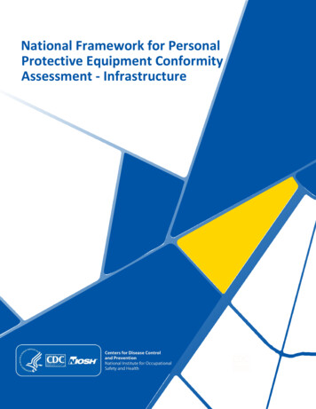
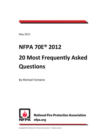
Each clamp is rated for a maximum and minimumconductor size. This provides the customers witha broad selection of equipment to specify for useby their line crews.A variety of other clamps for special uses areavailable. The All-Angle Clamp provides flexibilityover a wide range of cable and bus sizes and provides easy positioning with its pivoting body. TheCutout Ground Clamp provides a unique groundposition while also providing a physical barrierthat prevents accidental closure of the cutout fusetube as long as the clamp is installed in the lowerhinge of the cutout. The Cable Spiker Clamp wasdesigned to ensure the complete de-energizationof underground distribution cables with jacket overconcentric neutral. It determines the absence ofcable voltage when working mid-span before orafter removing and parking end span elbows formaintenance activity.Underground distribution ground sets are available for a wide variety of applications with URDtransformers and deadfront switchgear. Chancegrounding elbows are available with a fault dutyrating of 10,000 amps for 10 cycles.G42291SJAll AngleC6000729Transformer or SwitchGround SetC6000785Cutout Ground ClampT6001922Cable SpikerC6000619Mounted Substation ClampSpecial Purpose ClampsFigure 8-68-4ENCYCLOPEDIA OF GROUNDING
ASTM [6] ratings of clamps, ferrules and assemblies are shown in Table 8-1.Grounding Clamp Torque Strength,AShortCircuit PropertiesTable 8-1 Protective GroundCable, Ferrule, Clamp andAssemblyRatingsfor Symmetrical and Rating, Symmetrical kARMS, 60 Hzn-m15cycles(250ms)30cycles(500ms)Ultimate Rating CapacityCD ,Symmetrical kA RMS, 60 HzCopper Cable Size15cycles(250ms)30cycles(500ms)60cycles(1 s)MaximumCopper TestCable SizeContinuousCurrentRating, A RMS,60 534253/0473323250 kcmil3505330374004543304/0594229250 kcmil400633037400455439250 kcmil or 2 2/0704935350 kcmil450733037400457454350 kcmil or 2 4/0986948550 kcmil550Withstand and ultimate short circuit properties are based on performance with surges not exceeding 20% asymmetry factor.Yield shall mean no permanent deformation such that the clamp cannot be reused throughout its entire range of application.Ultimate rating represents a symmetrical current which the assembly or individual components shall carry for the specified time.DUltimate values are based upon application of Onderdonk's equation to 98% of nominal circular mil area allowed by Specifications B172 and B173.ABCTable 8-2 Ultimate Assembly Rating for High X/R Ratio ApplicationsHigh Asymmetrical Test RequirementsGradeSizeRating RatedCurrent (kA)X/R 301st Cycle Current Peak(kA)x2.69Last CycleCurrent Peak(kA)Test Duration(cycles)1HNo. H4/04712670156H250 MCM5514882157H350 MCM6818310115Note 1 - The above current values are based on electromechanical test values.Note 2 - Assemblies that have been subjected to these shall not be re-used.Note 3 - For use with currents exceeding 20% asymmetry factor.Note 4 - See X4.72 in ASTM F855 for additional information.Note 5 - Alternate testing circuits are available for laboratories that cannot achieve the above requirements. See ASTM F855 Appendix X4 fordetails.CHANCE LINEMAN GRADE TOOLS 8-5
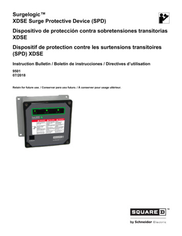
CableOver the years, many cable tests have been conducted and a great deal is known about its electricaland mechanical properties. Cable manufacturingprocesses are well established and when consistentprovide a reliable interconnection.The ultimate ratings shown in Table 8-1 wereoriginally calculated from an equation developedby Onderdonk[6]. They are based upon the time aknown current with an asymmetry factor less than20% can flow causing the cable to melt and separate, much like a fuse, thereby interrupting the flowof current. The withstand rating is approximately70% to 75% of the ultimate rating. It was includedin the ASTM F855 standard to emphasize the needto include a margin of safety when developing apersonal protective ground system.The values shown in Table 8-2 are based uponreduced values taken from EPRI Project RP2446Computer Program RTGC, "A Desktop ComputerProgram for Calculating Rating of TemporaryGrounding Cables" using an X/R ratio of 30.FerrulesA crimp ferrule should be used to interface thecable to the clamp. While it is possible to strip thecable insulation and insert it into the compressionterminal of a clamp, this results in significant risk ofequipment failure and should not be done. Whilecopper strands are new and shiny, tests showthat such an assembly functions at the rated current. However, as time passes, individual strandsexposed through the clamp compression fittingbecome corroded and start to break. Resistancebetween the exposed strands can increase substantially when this happens. Passing a high levelof fault current through this increased resistancegenerates a substantial amount of heating. Testresults have demonstrated the separation of cableand clamp due to this heating. In some cases, heatwas so intense that the pressure terminal actuallymelted and burned away from the clamp body. Thisresults in a complete loss of worker protection.provides protection against the entry of dirt andsome contaminants. Ferrules often are used witha short length of clear heat shrink material placedover the cable jacket and the base of the ferrule.This also helps to prevent the entry of moistureand other contaminants and provide stress relief.Unshrouded ferrulesTwo crimpsCableShrouded ferrulesSection ASect. BCableFigure 8-7Ferrules are available in aluminum, copper, and tinplated copper and are normally specified by thepreference of the end-user. A properly crimpedferrule reduces the entry of contaminants andprovides a strong, durable, and low resistanceconnection between the cable and clamp. Thereare sufficient variations of clamp, ferrule and conductor sizes and styles to meet every need forpersonal protective grounding. Many applicationsand the accompanying theory are presented inlater sections.Ferrule size must match the conductor size. Ferrules are made both with and without a shroud.See Figure 8-7. The shroud slips over the insulationand is crimped. By covering the cable insulation, it8-6ENCYCLOPEDIA OF GROUNDING
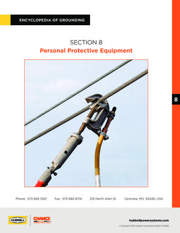
Voltage DetectorsVerification that a line is de-energized before attaching personal protective grounds are applied isa critical starting point. From this came the slogan“If it’s not grounded, it’s not dead.” There are several devices available to make this determination.Some involve temporary direct contact with the lineto make the measurement. Non-contact modelsare positioned near the line and held long enoughto make the reading. They make their measurements based upon the flow of capacitive leakagecurrent between the line and the Earth or nearbygrounded objects. Other devices operate similarto normal voltmeters. That is, they have two leadsthat can make contact with the line and a groundpoint to read the voltage present. Procedures forusing these devices is explained further in GeneralInstallation Procedures, Section 10.CHANCE Multi-Range Voltage Detectors (MRVD)are available in several measurement ranges,covering from 1 kV to 600 kV. They are availablewith either analog or digital meters. They areIf the line being measured is opened and floatingan induced voltage substantially lower or higherthan the system, voltage may be present if thatline shares poles or a corridor with other lines thatare energized. A capacitive induced voltage fallsto near zero as soon as the first grounded jumperis installed. This device is easy to read and doesrequire some interpretation by the user, but with theguidelines supplied is easily learned and becomesa very useful tool. Adapters are available to usewith underground distribution system equipmentsuch as transformers, switches, elbows, etc.The CHANCE Full Range Auto Ranging VoltageIndicator (ARVI) is available in ranges from 600volts to 500 kV. This is a direct-contact devicethat is mounted on an insulated universal poleof sufficient length to maintain a safe workingdistance for the worker. An audible alarm sounds ifthe voltage exceeds the system voltage. These arealso available with adapters for use on undergrounddistribution system components.Auto Ranging Voltage IndicatorFigure 8-9Multi-Range Voltage Detector (Analog)Figure 8-8designed for mounting on an insulated universal pole of sufficient length to maintain a safeworking distance for the worker. A metal probeis brought into contact with the line to take thereading. If the line is energized from a substationsource, the reading is that of the system voltage.CHANCE LINEMAN GRADE TOOLS The CHANCE Phasing Tester is available in wiredand wireless versions. While this tool was designedfor establishing the phase rotation of energizedlines, it can be used to determine a de-energizedline’s status. It is basically a two-probe voltmeter forhigh voltage applications. Each probe is insulatedand of sufficient length to maintain a safe workingdistance for the worker. One probe is placed incontact with the line to be measured and the otherto a ground or zero potential contact point. Themeasured voltage will again be either the systemor some induced voltage as described earlier.8-7
Phasing TesterFigure 8-10Wireless Phasing SetGround RodsA connection to the Earth by means of a drivenground rod consists of more than the metallic rodalone. In addition to the rod, it includes a series ofconcentric earthen shells around the rod. Currentflowing into the rod is radiated in all directionsthrough the entire surface area, creating a currentdensity measured in amperes per square inch. Itenters the thin earthen shell surrounding the rod.The surface area of this shell is larger than the rod.The total entering current now passes into thenext earthen shell, which has still a larger surfacearea. The level of amperes per square inch is further reduced. The current continues entering andleaving additional shells, each with successivelylarger surface areas, illustrated in Figure 8-11. Theresistance increases with each incremental increasein distance, but in smaller and smaller amountsbecause of the increasing surface area until a fullhemisphere is achieved. Resistance (R) of any pathis a function of the length (L) and cross section(A) of the current path, and of the resistivity (ρ)of the path.Withinthe shell,the surfacearea increases fasterthan theGroundRodand AssociatedEarthendistance from the rod. This results in a decrease in the exitingShellscurrent’s level of amperesper square inch faster than theincrease in distance. Thisis an exponentialdecrease and isFigure8-11shown in Figure 8-12.The implication of the discussion of earthen shellsand that of resistance is that as the distance be8-8ENCYCLOPEDIA OF GROUNDING
NOTE: The distance from the fault to points A and Bdepend on fault magnitude and soil resistivity.Resistance Approaches Constant ValueFigure 8-13Decrease in Current withDistance from the Earth Contact PointFigure 8-12comes greater, the resistance should also substantially increase. However, the increase in distanceis offset by an increase in cross section, as thecurrent spreads throughout the earthen path. So,the result is a non-linear change in the region ofthe shells. Beyond the boundary of the shell (orbetween two remote shells shown in Fig. 8-13) theresistance tends to approach a constant value.If the soil resistivity were constant, the resistanceof the path over the entire length might be con-sidered constant. However, soil resistivity variessubstantially with its make up. Some of the causesof variations are types of soil, presence and amountof moisture, sand or rock.The effective shell diameter equals twice that ofthe depth of the rod. Multiple rods used to makeparallel connection paths to Earth tend to losetheir parallel current carrying effectiveness if theshells substantially overlap.MAINTENANCE OF PERSONALPROTECTIVE EQUIPMENT29 CFR 1910.269 (n)(4)(i)[7] states that it is the utility’s responsibility to provide “protective groundingequipment” that “shall be capable of conductingthe maximum fault current that could flow (underlined by the author for emphasis) at the pointof grounding for the time necessary to clear thefault.” Further, 29 CFR 1910.269 (n)(4)(iii) states“Protective grounds shall have an impedance lowenough so that they do not delay the operation ofprotective devices in case of accidental energizingof the lines or equipment.” These two statementsimply a responsibility upon the employer.While not specified, these two statements imply aresponsibility to ensure equipment is maintainedfor use in a safe and usable state. In the past, littleCHANCE LINEMAN GRADE TOOLS CHANCE Ground Set Tester (C4033220)8-9
attention was paid to the condition of personalprotective jumpers. They often were coiled looselyand thrown into the back of a line truck by theworkers whose very lives depended upon them.This type of oversight must be corrected.Maintenance involves manual and visual inspectionand electrical testing. Electrical tests are used todetermine the condition of the clamp, ferrule andcable-to-ferrule interface. Convenient electricaltests have not been fully developed that will identify broken strands in the cable away from thecrimp ferrules, unless a very large number of thestrands are broken and not in contact with eachother. Most electrical tests make resistance measurements using various levels of test current forshort periods of time. If some strands are brokenbut still in contact with each other, held togetherby the outer jacket in the cable position, test current can still flow through both the broken andunbroken strands. The change in total resistanceover the length of the cable due to small strandbreakage usually cannot be seen.Test currents using the maximum continuous rating of the cable for a long-term test may heat thearea of the broken strands. The resulting heatingmay or may not be manually detected, again depending upon the amount of breakage. Infraredthermographs or thermocouples may improve thereading, but their use exceeds the definition of aconvenient field test. This test may take severalhours to complete. A careful manual inspection ofthe cable, feeling for the breaks, is the most reliablemethod of cable evaluation known at this time.It may not be practical to make micro-ohm resistance measurements on aluminum clamps usinga low voltage source. A coating of aluminum oxide covers bare aluminum surfaces. The coatingis described in thickness of molecules, ratherthan inches. Aluminum oxide is an insulator forvery low voltages, but it takes only a few volts tobreak down this layer and allow current to flow.The breakdown voltage can be as low as 5 to 10Volts. Levels below 1 Volt may give an incorrectresistance reading.The CHANCE Tester for Protective GroundingSets (C4033220) is a microprocessor-controlledtester for personal protective grounding sets . The8-10measurement made is the resistance from clampjaw surface to clamp jaw surface. The resistancevalue measured should be compared with table 2in ASTM F2249 to determine pass/fail.The CHANCE Ground Set Tester (C4033220)provides a 10V DC test voltage. This DC voltagelevel can easily break down any aluminum oxideto give a reliable reading on all personal protectiveground sets.There are other ground set testers on the markettoday that use an AC source for testing. These testsets may not apply a test voltage to the jumperhigh enough to break down any aluminum oxide onferrules, which could potentially give an incorrectreading. Possible errors are also noted in ASTMF2249-03, section 7.5.4 Note 3 and Note 4:Note 3 - AC testing measurements of groundingjumper assemblies are susceptible to errors andinconsistent results due to induction in the cableif the cable is not laid out per the test methodinstructions.Note 4 - AC testing measurements of groundingjumper assemblies are susceptible to errors ifmetal is laid across the cable or the cable is laidacross a metal object, even if the metal object isburied, such as a reinforcing bar embedded in aconcrete floor.Other benefits of using the CHANCE Ground SetTester include: Probing capability allows the user to locatehigh resistance areas within the ground set. Inductance of the cable or “coiling” thecable will not affect the readings. Grounding elbows can be tested withoutdisassembling. DC voltage is easy to work with in the repair/test facility.To ensure proper test procedures and methodsare applied when testing temporary groundingjumpers, refer to ASTM F2249-03 and the manufacturer’s instructions for proper use of the groundset tester.ENCYCLOPEDIA OF GROUNDING
ASTM F855 requires the resistance of a clamp tobe equal to or less than the same length of thelargest cable that the clamp will accommodate.The resistance of a new clamp and crimp ferrule tocable value can be in the range of 100 micro-ohms.When tested after use and extended atmosphericexposure, this value may substantially increase.Electrical testers can locate high resistance problems in the area of the clamp and ferrule on thejumper. A typical reading might be 500 micro-ohmsfor the clamp plus some resistance value for thelength of the cable. The increase in resistancesis typically the result of dirty or corroded clampjoints, loose inserts in the jaws or badly corrodedcable in the ferrule crimp joint. The reading willvary with the size of the cable and type of clamp.that may have been run over by a vehicle. If anyof these are found, replace the cable.Most ground sets can be returned to a usablecondition by performing this type of inspectionand maintenance on a periodic basis. Remember,the provision to supply suitable equipment is anOSHA requirement.For example a typical test using a tester withthe capability to make measurements in the micro-ohm range may be as follows. First, connectthe grounding assembly to the tester and makean end-to-end reading through the clamp, ferrulesand the interconnecting cable. If an unexpectedlyhigh reading is obtained, use the probe feature toisolate the high resistance area. Using the probes,make measurements from the connection post tothe clamp body. This measures the connection tothe jaws. Then measure from the clamp body tothe ferrule. This measures the connection betweenthese two parts. Then measure from the ferruleto a spot on the cable 1 foot from the ferrule exit.This measures the hidden crimp joint and cablecorrosion inside the ferrule. Repeat this procedureon both clamp ends.A high resistance reading from any of these indicates a need for maintenance. Disassemble theferrule from the clamp. Clean the clamp jaws andferrule connection and use a wire brush to removeany corrosion. If the high reading is from the ferrule to cable connection, cut off the ferrule andcrimp on a new one. The problem could be thatthe crimp was loosening, the cable strands werecorroding or strand breakage at the ferrule edge.If the above test does not show a high resistance,the reading will be originating from the cable itself.Make a careful manual inspection, as this is the mostreliable means of evaluating the interconnectingcable at this time. Feel for broken strands, corrosion lumps under the jacket or flattened spotsCHANCE LINEMAN GRADE TOOLS 8-11
of personal protective grounding equipment rating and style is the choice of the user, important criteria being its electrical and mechanical ratings. Equipment must be sized to provide the neces - sary worker protection if called upon to do so. It must be capable of carrying the