Transcription
DO’s AND DON’Ts OF PERSONAL PROTECTIVE GROUNDINGCopyright Material IEEEJames R. White CESCPShahid Jamil M.Sc., P.Eng.Senior Member, IEEEShermco Industries, Inc.2425 E. Pioneer DriveIrving, TX 75061USAjrwhite@shermco.comSenior Member, IEEEAbstract – Temporary protective grounding serves a criticalsafety function when working on electrical power systems.Although many field service personnel are well-familiar with therequirements of using temporary protective grounds, manyothers have only a partial understanding of important aspects ofit. This paper reviews the more important aspects of theapplication of temporary protective grounds, including sizing,order of placement and removal, results of misapplication andcommon rules for working with temporary protective grounds.4)5)6)7)8)Index Terms — Temporary protective grounds, electricalsafety, safety grounds, sizing grounds sets, inspecting groundsets, testing ground sets, grounding procedures, application ofgrounds.I. INTRODUCTIONThe use of temporary protective grounds when placingelectrical power systems into an electrically-safe work conditionrequires years of experience to fully understand and implement.For many less senior field service workers, what they learn abouttemporary personal protective grounds is often passed on by themore senior personnel. Although on-the-job training is animportant part of this type of training, it can also lead to workershaving gaps in their knowledge, leading to unsafe acts andpractices. Because the worker may not understand what theseunsafe acts are or their consequences, he or she may continueto perform this task in an unsafe manner and suffer injury ordeath as a result.II. APPLICABLE STANDARDS1910.269(n)(5) – lines and equipment shall be tested andfound absent of nominal voltage prior to placing grounds.1910.269(n)(6) – when attaching grounds, the ground endshall be attached first using live-line tools.1910.269(n)(7) – when removing grounds the connection tothe line or equipment shall be removed first using live-linetools.1910.269(n)(8) – the cable may not be grounded if there isa possibility of a hazardous transfer of energy during a fault.1910.269(n)(9) – grounds may be removed when requiredfor testing purposes.B. OSHA 29CFR1910.333(b)(ii)There is very little description about grounding in 1910.333Subpart S [2], as it applies to utilization equipment, although itcan apply to some types of medium-voltage equipment, such asmotor starters.1)Capacitors and high-capacitive lines and equipment shall beshorted and grounded.C. NFPA 70E Article 120NFPA 70E [3] requirements closely mirror those of the OSHAregulations. Changes have been made to reflect the 2021edition of the NFPA 70E. This section is now titled, “Process forEstablishing and Verifying an Electrically Safe Work Condition”.Establishing and verifying an electrically safe work conditionshall include all of the following steps, which shall be performedin the order presented, if feasible:A. OSHA 29CFR1910.269(n)The OSHA regulations in 1910.269(n) [1] are very basic andcan be vague. Anyone who has done any work on medium- andhigh-voltage electrical power systems should certainly knowwhat these basic requirements are:1)2)3)1910.269(n)(2) – temporary protective grounds shall havean impedance low enough to allow immediate operation ofthe overcurrent protective device (OCPD).1910.269(n)(3) – temporary protective grounds shall beplaced to create an equipotential zone.1910.269(n)(4) – temporary protective grounds shall besized to carry the maximum short circuit available current forthe time necessary to clear the fault. Grounds shall be nosmaller than No. 2 AWG copper.(1) Determine all possible sources of electrical supply to thespecific equipment. Check applicable up-to-date drawings,diagrams, and identification tags.(2) After properly interrupting the load current, open thedisconnecting device(s) for each source.(3) Wherever possible, visually verify that all blades of thedisconnecting devices are fully open or that drawout-type circuitbreakers are withdrawn to the test or fully disconnected position.(4) Release stored electrical energy.1
(5) Block or relieve stored nonelectrical energy in devices tothe extent the circuit parts cannot be unintentionally energizedby such devices.a. Placement. Temporary protective grounding equipmentshall be placed at such locations and arranged in such a manneras to prevent each employee from being exposed to a shockhazard (i.e., hazardous differences in electrical potential). Thelocation, sizing, and application of temporary protectivegrounding equipment shall be identified as part of the employer’sjob planning.(6) Apply lockout/tagout devices in accordance with adocumented and established procedure.(7) Use an adequately rated portable test instrument to testeach phase conductor or circuit part to test for the absence ofvoltage. Test each phase conductor or circuit part both phase-tophase and phase-to-ground. Before and after each test,determine that the test instrument is operating satisfactorilythrough verification on any known voltage source.b. Capacity. Temporary protective grounding equipment shallbe capable of conducting the maximum fault current that couldflow at the point of grounding for the time necessary to clear thefault.Informational Note: ASTM F855, Standard Specification forTemporary Protective Grounds to be Used on De-energizedElectric Power Lines and Equipment, is an example of astandard that contains information on capacity of temporaryprotective grounding equipment.Exception No. 1 to 7: An adequately rated permanentlymounted absence of voltage tester shall be permitted to be usedto test for the absence of voltage of the conductors or circuit partsat the work location, provided it meets all of the followingrequirements:(1) It is permanently mounted and installed in accordance withthe manufacturer’s instructions and tests the conductors andcircuit parts at the point of work;(2) It is listed and labeled for the purpose of testing for theabsence of voltage;(3) It tests each phase conductor or circuit part both phase-tophase and phase-to-ground;(4) The test device is verified as operating satisfactorily on anyknown voltage source before and after testing for the absence ofvoltage.c. Impedance. Temporary protective grounding equipmentand connections shall have an impedance low enough to causeimmediate operation of protective devices in case ofunintentional energizing of the electric conductors or circuit parts.D. IEEE 3007.3The color book series of IEEE standards is being replaced bywhat is known as the “dot” series of standards. IEEE 3007.3,Section 7.4.3 [4] covers the use of personal protective groundsand basically covers the same information as NFPA 70E.Exception No. 2 to 7: On electrical systems over 1000 volts,noncontact capacitive test instruments shall be permitted to beused to test each phase conductor.E. IEEE C2InformationalNoteNo. 1: SeeUL 61010-1, SafetyRequirements for Electrical Equipment for Measurement,Control, and Laboratory Use, Part 1: General Requirements, forrating, overvoltage category, and design requirements forvoltage measurement and test instruments intended for use onelectrical systems 1000 volts and below.The National Electric Safety Code (NESC) [5] primarily coversoperations and work practices for overhead and undergroundline work. It again covers mostly the same information as theOSHA regulations, but adds more detail in the performance ofthose requirements. As an example, Section 445 coverspersonal protective grounds. 445A covers the installation ofgrounds and states:Informational No. 2: For additional information on rating anddesign requirements for permanently mounted absence ofvoltage testers, refer to UL 1436, Outlet Circuit Testers andOther Similar Indicating Devices.Informational Note No. 3: For additional information on ratingand design requirements for voltage detectors, refer to IEC61243-1, Live Working — Voltage Detectors — Part 1:Capacitive type to be used for voltages exceeding 1kV a.c., orIEC 61243-2, Live Working — Voltage Detectors — Part 2:Resistive type to be used for voltages of 1kV to 36 kV a.c., or IEC61243-3, Live Working — Voltage Detectors — Part 3: Two-polelow voltage type.“A. Installing groundsWhen installing protective grounds on a previously energizedpart, the following sequence and precautionary measures shallbe observed.EXCEPTION: In certain situations, such as when groundingconductors are supported on some high-voltage towers, it maybe appropriate to perform the voltage test before bringing thegrounding device into the work area.B. Current-carrying capacity of groundsThe grounding device shall be of such size as to carry theinduced current and anticipated fault current that could flow atthe point of grounding for the time necessary to clear the line.NOTE: Refer to ASTM F-855-04 [B24] for specifications forprotective grounding equipment.2. Initial connectionsBefore grounding any previously energized part, the employeeshall first securely connect one end of the grounding device toan effective ground. Grounding switches may be employed to(8) Where the possibility of induced voltages or storedelectrical energy exists, ground all circuit conductors and circuitparts before touching them. Where it could be reasonablyanticipated that the conductors or circuit parts being deenergized could contact other exposed energized conductors orcircuit parts, apply temporary protective grounding equipment inaccordance with the following:2
connect the equipment or lines being grounded to the actualground connections.3. Test for voltageThe previously energized parts that are to be grounded shall betested for voltage except where previously installed groundsare clearly in evidence. The employee shall keep every part ofthe body at the required distance by using insulating handles ofproper length or other suitable devices.4. Completing groundsa. If the part shows no voltage, the grounding may becompleted.b. If voltage is present, the source shall be determined toensure that presence of this voltage does not prohibitcompletion of the grounding.c. After the initial connections are made to ground, thegrounding device shall next be brought into contact with thepreviously energized part using insulating handles or othersuitable devices and securely clamped or otherwise securedthereto. Where bundled conductor lines are being grounded,grounding of each subconductor should be made.Only then may the employee come within the distances fromthe previously energized parts specified in Rule 441A orproceed to work upon the parts as upon a grounded part.”equipment and is free-standing. The grounding used for thispurpose is much smaller and does not have the samerequirements as temporary protective grounds. The lines orequipment connected to such a transformer would usetemporary protective grounds in order to protect against lightningstrikes or reenergization.Temporary protective grounds must meet the requirements ofASTM F855[6]. Each component (clamp, ferrule and cable) ofthe ground set must be designed and constructed to carry themaximum short circuit available current and for the type offixture it will be attached to. A clamp designed for flat bus willnot work well on tubular bus, or vice versa. One of the authorshas heard field technicians explain their choice of ground setsby saying “We use 4/0 AWG; it should be enough.” It isadvisable to understand how to size temporary protectivegrounds and not rely on intuition or old practices. Don’t takeshortcuts and improvise as shown in Figure 1.All of the aforementioned standards contain very much thesame information. The devil’s in the details though, and thatis what this paper is about.III. GROUND SET FIELD USE REQUIREMENTSThere are different types of grounds for different purposes.Temporary protective grounds guard against the accidentalreenergizing of circuits or equipment. “Static” grounds are onlyused to prevent isolated electrical devices from accruing a staticcharge from induced voltages. An example of static groundingwould be the shorting and grounding used when testing atransformer that is electrically isolated from all other lines andFig. 1 – Example of Unsafe Improvisation3
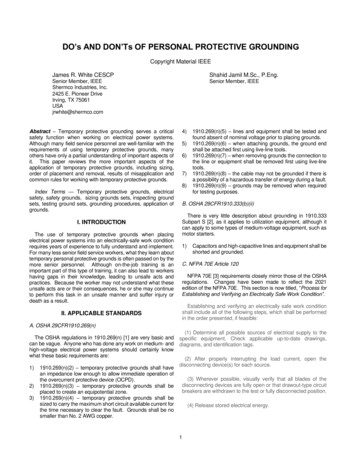
Table 1 Protective Ground Cable, Ferrule, Clamp and Assembly Ratings for Symmetrical CurrentFrom ASTM F855A. Sizing Temporary Protective Groundsset. Longer ground set cable also increases the risk of someonebeing struck by the cable if it is reenergized. When a ground setis energized it may whip about due to the magnetic forces beingimposed upon it. Ground cables energized under suchcircumstances may cause significant personal injuries.Table 1 (shown as Table 1 above) from ASTM F855 is used todetermine the sizing of temporary protective grounds basedon the available short circuit current and clearing time of theOCPD. Table 2 is used when applications have a high X/Rratio. There are two ratings given in Table 1; “withstand” and“ultimate”. Quoting from ASTM F855:1)“3.1.5 ultimate capacity—this represents a current which itis calculated the component is capable of conducting forthe specified time. It is expected that component damagemay result. The component shall not be reused, except intest situations.2)3.1.6 withstand rating—this represents a near symmetricalcurrent which shall be conducted without any componentbeing damaged sufficiently to prevent being operable andreusable. The protective ground shall be capable of passinga second test at this current after being cooled to ambienttemperature.”B. Installation and RemovalAn appropriate sequence for installation and removal oftemporary protective grounds could be as follows:1) Test for the absence of nominal voltage. OSHA and NFPA70E state that all circuits are to be considered energizeduntil proven deenergized by testing. There may be inducedvoltage showing, but it will be much lower than the systemoperating voltage.2) Always use live-dead-live testing (also known as “ThreeStep Voltage Test”) when performing absence of voltagetests. Test the voltage detector on a known live circuit, testall circuits that should be deenergized, then retest thevoltage detector on a known live circuit. Voltage detectorscan and do stop working and the author has had severalvoltage detectors go bad after the initial test. Followingproper procedures, even when you are certain the circuitis dead, could save your life.3) Never, ever tap a circuit or device with a “static ground” tosee if it is dead. Back in the day, electrical workers wouldtake a 12 AWG wire and staple it to a broomstick handle.One end was connected to ground while the other end wasstripped bare. The bare end was used to tap the“deenergized” conductor to ensure it was dead. This isanother form of improper improvisation. If the circuit is stillenergized the short circuit current could vaporize the wire,creating an arc flash with the potential for serious injury ordeath.As a matter of leaving some safety factor into the choice, usingground sets sized to the withstand rating would be advisable.The amount of time for OCPD operation should be based on thepower systems characteristics.One other factor to consider is the length of the grounding setcable. The longer the cable length, the higher the impedance ofthe cable will be. The goal is to have the lowest impedancepractical so the short circuit current will flow to ground throughthe ground set causing as little damage as possible. A groundset not rated for available fault current would act like a fuse andcreate a potential for injury and property damage. In discussionsat the ASTM F18 committee meetings it was generally agreedthat 20’ is the longest length a grounding cable should have.Cable longer than 20’ begins to affect the ampacity of the ground4
4)5)Connect the ground-side connection securely. Ensure thelocation where the grounds are to be placed is clean andfree from anything that could cause high impedance.Common practice is to wire-brush the surface or to use theserrated jaws of the ground clamp to clean the surface area.The ground-side clamp must always be securely attachedfirst. If there is an induced potential on the lines orequipment or the line is inadvertently left energized and theline-side is attached first, the entire ground set would beenergized. By attaching the ground-side first, that potentialwould be dissipated.Use only ground clamps that are intended for use with thetype of bus or equipment being attached to. Using a clampintended for tubular bus or vice versa will not allow theproper clamping force needed and the clamp may comeloose during a short circuit.This would result inconsiderable damage to equipment and possible injury toanyone nearby. Figure 2 shows a poorly-mated clampconnection.9)subject to reenergization or fault-level currents. Alwayswear rubber insulating gloves when placing or removingstatic grounds.Wear proper personal protective equipment (PPE) whenexposed to electric shock and arc flash hazards. Yes, it ishot, it is bulky, it does make you sweat but it will alsoprotect you if there’s an arc flash or shock potential. OSHA1910.269 does not give details of what PPE is to be usedwhen applying and removing protective grounds. NFPA70E Table 130.7(C)(15)(a) lists use of HRC 2, 3 and 4based on type and voltage of the equipment, but only whenthe grounds are applied. Electric hazards also exist whenthe grounds are being removed and workers need to useappropriate PPE for their protection. Workers need to askthemselves what would happen if there’s a lightning strikeor inadvertent equipment reenergization when grounds arebeing removed.Fig. 3Example Arc Flash Warning Label10) Place grounds close enough to protect workers, but not soclose that they could injure people nearby. Refer toparagraph C for more information.11) Never come into contact with grounds while they are beingplaced or afterwards. The jacket on grounds is used toprotect the fine conductors from being damaged, not asinsulation. Don’t step on them or reposition them usingbare hands. The jacket would be of little use on highervoltage electrical systems.12) Inspect grounds before using them. ASTM F2499 [7]provides guidance on the proper inspection and testing ofground clusters. Figure 4 is a common problem found onground sets. In Figure 4, the cable is oxidized, the strandsare exposed to damage, etc. Some of the other reasonswhy ground sets may get damaged or become ineffectiveare: human errors, lightning strikes, static build-up,induced voltage feedback from adjacent circuits,mechanical or equipment failure, switching errors, storedcharges from capacitors, faulty automatic re-closingdevices, corrosion, contact with chemicals, accidentalpinching, mishandling, etc.Fig. 2Incorrect Clamp Used for Application6)7)8)Using a live-line tool only, connect the other clamps to theconductors or equipment. OSHA 1910.269 specificallystates that a live-line tool is to be used when attaching orremoving ground sets. The use of a live-line tool removesthe worker from the immediate vicinity if the line were tobecome reenergized for some reason and also places theworker beyond the Restricted Approach Boundary (whatOSHA refers to as the Minimum Safe Approach Distance fora qualified person).Use a ground set as short as possible. This reduces thechances of the cable striking someone if it is accidentallyreenergized and also reduces the overall impedance of theground set.If a ground set has “T” handles, it is to be used for staticgrounds only.They are suitable for use when atransformer or other piece of isolated electrical equipmentmust be grounded during an electrical test and can’t be5
Fig. 4Defective Ground Clamp Assembly13) Always track ground sets when placing them on equipmentor circuits. Every year accidents are caused by groundsbeing left on when a system is reenergized. If sized andinstalled properly, the OCPD should clear the circuit beforesubstantial damage is done.One company uses thealerting and tagging system shown in Figure 5A and 5B.Each ground set has a unique identification (ID) number thatis stamped into a metal tag. That ID tag is attached to theground set and to a removable clip. When the ground set isplaced into service, the tag is unclipped from the ground setand locked onto the LOTO device, which also has a tagshowing which circuit it is placed on. When the LOTO isreleased, the technician knows which ground has to beretrieved and where it is.Fig. 6A and 6BOne Company’s Alerting & Tagging Signs15) Another, possibly less effective practice, is to count thenumber of grounds applied before and after theswitching is carried out.16) If grounds are defective, tag them and remove themfrom service. The same tagging system used to identifyeach ground set, can also be used to track and inspectground sets for condition and testing. If the ground setis defective, that ID number is entered into the system,the grounds removed from service and the grounds arerepaired and tested or disposed of. The grounds mustnot be put back in service until these are repaired andtested by an accredited testing laboratory.17) Never stand near grounds that may be lying on theground. If they are reenergized they will try tostraighten out with great force and may hit workers inthe vicinity. Using safety barrier tape or barriers couldmake other workers aware of the hazard and avoid thearea.18) Never coil grounds. If they are on carriers, remove theentire conductor from the carrier and stretch it out onthe ground (earth). When short circuit current tries topass through a coil of wire, the coil acts as an inductoror choke. Often the result is vaporized conductor.Fig. 5A and 5BOne Company’s Tracking System14) Another practice successfully used by one global energycompany to ensure grounds are removed is to include bothapplication and removal of grounds in the electricalequipment switching procedures where qualified personsstrictly follow each and every step of the switchingprocedure and sign or initial the steps after their execution.This practice is further enhanced by hanging yellow“Grounds Applied” tags on the door of the equipment wheregrounds are applied, shown as Figures 6A and 6B.6
19) Inspect the grounds after using them. Take a few minutesto ensure they are still serviceable. Use ASTM F2499 as aguide for your inspection.20) Test personal protective grounds on a regular basis. ASTMF2499 states that grounds are to be tested at a “time intervalestablished by the user to ensure that defective groundingjumper assemblies are detected and removed from servicein a timely manner”. It is the author’s opinion that personalprotective grounds are safety-related devices and, as such,should be tested annually.C. Placement Of GroundsLocation of personal protective grounds either ensures orjeopardizes the safety of workers. Therefore, it is essential thatgrounds be placed between all possible energy sources and theworkers. The following illustrates proper ground placement forvarious electrical systems:1) In radial power systems, where there is only one energysource, grounds are applied at the transformer secondary orswitchgear when any work is to be done at the switchgear.2) In secondary selective systems when any work is to be doneat the switchgear bus, grounds are applied near the tiebreaker and incoming breaker connections. This approachallows the worker to remain between the grounds andgrounds protect the worker from any accidentalreenergization.3) When any work is to be done on overhead lines, groundsare applied at both ends of the power line section or polebeing worked on to protect workers from lightning andaccidental reenergization.4) It is necessary that all temporary energy sources (includingportable, short term or construction power generators, orpotential backfeeds) are investigated, isolated, locked,tagged and grounded.Fig. 7Ball-and-Socket Ground ClusterThe ball and socket ground sets can have more surfacecontact than clamps, and are easier to apply using live-line tools.The ball and socket ground set is especially useful when usedon medium-voltage metal clad switchgear or other equipmentusing flat bus and comes in several mounting configurations.D. The Best Ground Set?Tests performed by one major utility company indicate that theball and socket style of ground set may be superior to other stylesin terms of lowest resistance and ease of use. This type ofground set can only be used when the correct ball stud isinstalled into the bus during a shutdown. Once installed, the ballstud is easily accessed by removing the rubber cover using alive-line tool, Figures 8a and 8b.Figs. 8a and 8bBall-and-Socket Ground Cluster as Used on Switchgear7
on the ASTM F18 Committee “Electrical Protective EquipmentFor Workers”. Jim is an IEEE Senior Member and in 2011received the IEEE/PCIC “Electrical Safety Excellence” award. In2013 Jim received NETA’s “Outstanding AchievementAward”. Jim is a past Chairman (2008) of the IEEE ElectricalSafety Workshop and is the author of three books availablethrough American Technical Publishers, “Significant Changes toNFPA 70E – 2015 Edition”, “Electrical Safety, A Practical Guideto OSHA and NFPA 70E” and “Circuit Breakers – A Technician’sGuide to Low and Medium-Voltage Circuit Breakers”.IV. CONCLUSIONSPersonal protective grounds provide a safe, reliable method toprotect workers from hazards that may occur while the electricalpower system is deenergized. This includes unanticipatedevents, such as lightning strikes, induced potentials andaccidental reenergizing of the system.This paper reviewed a number of important standards andfield-use requirements to observe while choosing and usingpersonal protective grounds and is not intended as advice withrespect to specific installations. As an overview, the authorscannot foresee all possible needs in actual field use. Fieldservice technicians and linemen who use personal protectivegrounds must assess the conditions and needs at the site andtime of use in consultation with their electrical experts.Shahid Jamil (S’74, M’75, SM’96, Emeritus’12) received B.Sc.and B.Sc. (Elect. Eng.) Degrees from Aligarh Muslim University,India, and M.Sc. (Elect. Eng.) degree from Queen’s University,Kingston, Canada. He joined the Iron Ore Company of Canada,Labrador City, Canada, in 1975. In 1979, he joined Imperial Oil’sEsso Chemical Canada (Exxon) Plant, Redwater. In 1988, hemoved to Imperial Oil’s Strathcona Refinery in Edmonton. In1991, he started an assignment at Exxon Chemical's BaytownPlant in Texas, where he was responsible for the development,design, and startup support for electrical projects, technicalsupport for the operation, maintenance and troubleshooting ofthe plant electrical power system, etc. In Baytown, he was alsoresponsible for the interpretation and implementation ofapplicable safety regulations and standards, upgrade of plantelectrical safety standards, and procedures and compliance. In1998, Shahid moved to Thailand to support the start-up of ExxonChemical's Aromatics expansion project. In 1999, Shahidmoved to Singapore for the start-up of ExxonMobil ChemicalCompany's new chemical complex project.Shahid has been very active in the area of electrical safety andhas authored/co-authored 8 electrical safety papers and receivedthree “First Paper” and one "Honorable Mention" awards fromPCIC/IEEE and “Third Best Presentation” award from PCIC/IEEEElectrical Safety Workshop. Shahid has chaired/cochaired/coordinated three PCIC/IEEE Electrical SafetyWorkshops in Indianapolis (1997), Madras, India (1998) andNew-Delhi (2000). He has co-presented papers and tutorial atinternational conferences and workshops, developed trainingprograms and carried out electrical safety training for over 1500qualified and unqualified workers in Canada, India, Indonesia,Singapore, Thailand, the USA and South American Countries.US Immigration and Naturalization Services recognizedexceptional experience and expertise in Electrical Safety andgranted the Permanent Residence (Green Card).Shahid was the recipient of 2009 IEEE/PCIC Excellence inElectrical Safety award for "Outstanding dedication andcontributions made to advance and accelerate the dispersion ofinformation and knowledge impacting electrical safety throughactivities within and outside the Petroleum and ChemicalIndustry Committee.”V. ACKNOWLEDGEMENTSThe authors wish to acknowledge the assistance of thetechnical reviewers in the preparation of this paper.VI. REFERENCES[1][2][3][4][5][6][7]OSHA 29CFR1910.269, Electric Power generation,Transmission and Distribution, 1994.OSHA 29CFR1910.333, Selection and Use of WorkPractice.NFPA 70E, Standard for Electrical Safety in the Workplace,2012 edition, National Fire Protection Association.IEEE Standard 3007.3, IEEE Recommended Practice forElectrical Safety in Industrial and Commercial PowerSystems, 2012, International Association of Electrical andElectronic EngineersIEEE Standard C2, National Electrical Safety Code, 2012,International Association of Electrical and ElectronicEngineersASTM Standard F855, Standard Specification forTemporary Protective Grounds to be Used on Deenergized Electric Power Lines and Equipment, 2009,American Society for Testing and MaterialsASTM Standard F2249, Standard Specification forIn-ServiceTestMethodsforTemporaryGrounding Jumper Assemblies Used on De Energized Electric Power Lines and Equipment ,2009, American Society for Testing andMaterialsVII. VITAJames R. (Jim) White has been the Training Director of ShermcoIndustries, Inc., in Irving, Texas since 2001. Jim is certified bythe National Fire Protection Association (NFPA) as a CertifiedElectrical Safety Compliance Professional (CESCP). He is theprincipal member for Shermco Industries on the NFPA TechnicalCommittee “Recommended Practice for Electrical EquipmentMaintenance” (NFPA 70B). Jim represents the interNationalElectrical Testing Association (NETA) as an alternate memb
location, sizing, and application of temporary protective grounding equipment shall be identified as part of the employer’s job planning. b. Capacity. Temporary protective grounding equipment shall be capable of conducting the maximum fault current that could flow at the point of grounding for the time necessary to clear the fault.