Transcription
Facilities Instructions, Standards, and TechniquesVolume 5-1Personal Protective Grounding forElectric Power Facilities and PowerLinesU.S. Department of the InteriorBureau of ReclamationDenver, ColoradoJuly 2005
Form ApprovedOMB No. 0704-0188REPORT DOCUMENTATION PAGEPublic reporting burden for this collection of information is estimated to average 1 hour per response, including the time for reviewing instructions, searching existing data sources, gathering and maintaining the dataneeded, and completing and reviewing this collection of information. Send comments regarding this burden estimate or any other aspect of this collection of information, including suggestions for reducing thisburden to Department of Defense, Washington Headquarters Services, Directorate for Information Operations and Reports (0704-0188), 1215 Jefferson Davis Highway, Suite 1204, Arlington, VA 22202-4302.Respondents should be aware that notwithstanding any other provision of law, no person shall be subject to any penalty for failing to comply with a collection of information if it does not display a currently valid OMBcontrol number. PLEASE DO NOT RETURN YOUR FORM TO THE ABOVE ADDRESS.1. REPORT DATE (DD-MM-YYYY)TT2. REPORT TYPET3. DATES COVERED (From - To)TTJuly 2005TFinal4. TITLE AND SUBTITLE5a. CONTRACT NUMBERTFIST 5-1Personal Protective Grounding for Electric Power Facilities and Power Lines5b. GRANT NUMBER5c. PROGRAM ELEMENT NUMBER6. AUTHOR(S)5d. PROJECT NUMBERPhil Atwater, Electrical Engineer, P.E.Bureau of ReclamationInfrastructure Services DivisionHydroelectric Research and Technical Services GroupDenver, Colorado5e. TASK NUMBER5f. WORK UNIT NUMBER7. PERFORMING ORGANIZATION NAME(S) AND ADDRESS(ES)8. PERFORMING ORGANIZATION REPORTNUMBERBureau of ReclamationDenver Federal CenterPO Box 25007Denver CO 80225-0007FIST 5-19. SPONSORING / MONITORING AGENCY NAME(S) AND ADDRESS(ES)10. SPONSOR/MONITOR’S ACRONYM(S)Hydroelectric Research and Technical Services GroupBureau of ReclamationMail Code: D-8450PO Box 25007Denver CO 80225-0007DIBR11. SPONSOR/MONITOR’S REPORTNUMBER(S)12. DISTRIBUTION / AVAILABILITY STATEMENTAvailable from the National Technical Information Service, Operations Division,5285 Port Royal Road, Springfield, Virginia 2216113. SUPPLEMENTARY NOTEST14. ABSTRACTThe purpose of this document is to establish clear and consistent instructions and procedures for temporary grounding of deenergized and isolated high-voltage equipment (over 600 volts) for the purpose of bare-hand contact.These instructions and procedures supplement the requirements in Reclamation Safety and Health Standards. Adherence tothese procedures will enable workers to perform their duties with maximum confidence and safety. In the event of adifference between the requirements in this FIST and those contained in the Reclamation Safety and Health Standard, themore rigorous requirement shall apply.15. SUBJECT TERMSpersonal protective grounds, high-voltage equipment16. SECURITY CLASSIFICATION OF:a. REPORTULb. ABSTRACTUL17. LIMITATIONOF ABSTRACTc. THIS PAGEULUL18. NUMBEROF PAGES7719a. NAME OF RESPONSIBLE PERSONTPhil Atwater19b. TELEPHONE NUMBER (include area code)303-445-2304S Standard Form 298 (Rev. 8/98)P Prescribed by ANSI Std. 239-18
Facilities Instructions, Standards, and TechniquesVolume 5-1Personal Protective Grounding forElectric Power Facilities and PowerLinesHydroelectric Research and Technical Services GroupInfrastructure Services DivisionU.S. Department of the InteriorBureau of ReclamationDenver, ColoradoJuly 2005
DISCLAIMERThis written matter consists of general information for internal Bureau of Reclamation operations andmaintenance staff use. The information contained in this document regarding commercial products orfirms may not be used for advertising or promotional purposes and is not to be construed as anendorsement of any product or firm by the Bureau of Reclamation.
ContentsPage1. Purpose and Scope .1.1Purpose.1.2Scope.1.3Responsibility .1.4Cancellation .111112. Definitions and Interpretations .23. Determine Need for Personal Protective Grounding .3.1Uses Permitted .3.1.1 Over 600 Volts (Required).3.1.2 Less Than 600 Volts (Optional).3.2Uses Not Permitted .3.2.1 Lightning.3.2.2 Over 50,000 Amperes Available Fault Current .3.2.3 Nontemporary Installations.4. Basic Criteria for Safe Grounding Practices.4.1Electric Shock Hazard.4.2Protective Grounding Requirements.333444555675. Ground Cable Assemblies.5.1Grounding Cable.5.1.1 Cable Ampacity .5.1.2 Parallel Grounds.5.2Grounding Cable Jackets .5.3Grounding Clamps .5.3.1 Clamp Types .5.3.2 Clamp Jaws .5.4Ground Cable Ferrules.99101212121313146. Application of Protective Ground Cables .6.1Determine Maximum Available Fault Currentat Worksite .6.2Size the Cables.6.2.1 Cable Size .6.2.2 Cable Length.6.3Inspect Ground Cable Assemblies .6.4Obtain a Clearance.6.5Confirm De-Energized Status (arc flash hazard analysisrequired).6.5.1 Hot Stick .6.5.2 Noisy Tester .6.5.3 Hot Horn or Noisy Tester .6.5.4 Multiple Range Voltage Detector .6.5.5 Neon-Type Indicator.6.5.6 Direct-Reading Voltmeter.15iii16171717212121212222222222
ContentsPage6.6Clean Connections (arc flash hazard analysis required) .6.6.1 Wire Brushing.6.6.2 Self-Cleaning Clamps .Grounding Cable Installation.6.7.1 Ground-End Clamps .6.7.2 Circuit-End Clamps (arc flash hazard analysisrequired).6.7.3 Multiphase, Worksite Grounding Required.6.7.4 Parallel Grounds.6.7.5 Barricade .6.7.6 Removal .Arc Flash Hazard Analysis Required.2425252525267. Power and Pumping Plant Protective Grounding .7.1Three-Phase Tee Grounding .7.2Double-Isolation Grounding .2627298. Switchyard and Substation Protective Grounding .8.1General Considerations for Placement of ProtectiveGrounds.8.2Power Circuit Breakers and Transformers.8.3Disconnect Switches and Bus .8.4Insulated High-Voltage Cable.8.4.1 Cable Terminations.8.4.2 Midsection and Splices .8.4.3 Cable Testing .8.5Grounding Transformers and Phase Reactors.8.6Capacitor Banks .8.7Mobile Equipment .31323333343435363636379. Power Line Protective Grounding .9.1Grounding on Metal Transmission Structures .9.1.1 Lattice Steel Structures .9.1.2 Slip Joint Steel Pole Structures .9.1.3 Weathering Steel Pole Structures.9.1.4 Painted Steel.9.1.5 Overhead Ground Wires .9.1.6 Structure Footing Ground .9.2Grounding on Wood Pole Transmission Structures.9.3Transmission Line Terminal Ground Switches .9.4Grounding on Distribution Lines .9.5Surface Equipment and Vehicle Grounding .9.5.1 Aerial Devices.9.5.2 Contact With Grounded Vehicles at 32323
ContentsPage9.6Opening or Splicing Aerial Conductors.9.6.1 Splicing at Ground Level .9.6.2 Splicing From Aerial Lift Equipment .Grounding Insulated Power Cable .4545464710. Care, Inspection, and Testing Protective Grounding Equipment .10.1 Care .10.2 Inspection.10.2.1 Ground Cable Assemblies.10.2.2 Live-Line Tools .10.3 Testing.10.3.1 Ground Cable Assemblies.10.3.2 Live-Line Tools .10.4 Records .4848484849494952529.7ReferencesAppendix A – Qualitative Effects of Electric Current on the Human BodyAppendix B – Derivation of Safe Exposure Voltage for Shock SurvivalAppendix C – Example Protective Ground Cable SizingAppendix D – Example Powerplant Grounding Worker ExposureVoltage CalculationAppendix E – Double-Isolation Grounding for Generators Connected toa Common Step-Up Power TransformerAppendix F – Technical Considerations in Protective Grounding onTransmission Lines, Substations, and SwitchyardsAppendix G – Protective Grounding Procedure Flow Chartv
July 2005Page 1 of 81FIST 5-1PERSONAL PROTECTIVE GROUNDING FOR ELECTRIC POWER FACILITIESAND POWER LINES1.PURPOSE AND SCOPE1.1 PurposeThis Facilities Instructions, Standards, and Techniques (FIST) Volume is to establishclear and consistent instructions and procedures for temporary grounding of deenergized and isolated high-voltage equipment (over 600 volts) for the purpose ofbare hand contact. This FIST applies to those facilities of the Federal power andwater systems for which the Bureau of Reclamation (Reclamation) and itscontractors and agents are responsible, and includes power and pumping plants,switchyards and substations, and transmission lines.A current copy of this document shall be readily available at each Reclamation officeand facility and to each employee that works on equipment required to be protectivegrounded. A quick reference guide to grounding procedure contained in this FIST ispresented in flow chart format in appendix G.1.2 ScopeThese instructions and procedures supplement the requirements in ReclamationSafety and Health Standards, “yellow book”. [1] Adherence to these procedures willenable workers to perform their duties with maximum confidence and safety. In theevent of a difference between the requirements in this FIST and those contained inthe Reclamation Safety and Health Standard, the more rigorous requirement shallapply.1.3 ResponsibilityAny employee working on de-energized high-voltage equipment is responsible forunderstanding protective grounding requirements and procedure. Facility managersand supervisors are responsible for ensuring that workers are knowledgeable of andcomply with grounding procedure in this FIST. Only trained and qualified workersshall apply and remove temporary personal protective grounds.1.4 CancellationThis FIST Volume replaces FIST Volume 5-1, Personal Protective Grounding, datedJanuary 1993.
Page 2 of 81July 2005FIST 5-1PERSONAL PROTECTIVE GROUNDING FOR ELECTRIC POWER FACILITIESAND POWER LINES2. DEFINITIONS AND INTERPRETATIONSExposure voltage. A short-duration difference in potential between conductiveobjects that a person may contact when personal protective grounds or a groundingsystem conduct fault current. Also applicable to transferred potential betweenseparately grounded systems (stations), or difference in earth surface potentials.Grounding (ground). The connection of conductive parts of lines, structures, andequipment to earth or other conductive medium (grounding system) that substitutesfor earth, e.g. station ground mat conductors.Grounded worksite. A work area that is made an equipotential safe working zoneby the application of personal protective grounds.Personal protective grounding (grounds). Cable connected to de-energized linesand equipment by jumpering and bonding with appropriate clamps, to limit thevoltage difference between accessible points at a worksite to safe values if the linesor equipment are accidentally re-energized. Protective grounds are sized to carry themaximum available fault current at the worksite. Also called ground jumper.Static ground. Any grounding cable or bonding jumper (including clamps) that hasan ampacity less than the maximum available fault current at the worksite, or issmaller than #2 A.W.G. (American Wire Gage) copper equivalent. Static groundsare used for potential equalizing between conductive parts in groundingconfigurations that cannot subject them to significant current. Therefore, smallerwire which provides adequate mechanical strength is sufficient (e.g. #12 A.W.G.).Station. For protective grounding purposes, any electrical facility with a groundingelectrode system (ground mat) which bonds all conductive, non-current carryingparts of equipment and for the control of surface potential gradients. Two or moredistinct but adjacent facility grounding electrode systems that are intentionallybonded (e.g. a powerplant and adjacent switchyard grounding systems) may beconsidered a common station grounding system. Grounding systems that areintentionally bonded but not physically adjacent are considered separately grounded.Step voltage. The difference in surface potential experienced by a person bridging adistance of one meter with the feet without contacting any other grounded object. [5]Touch voltage. The difference in potential between a grounded structure or stationand the surface potential at the point where a person is standing while at the sametime having a hand in contact with the grounded structure or object. [5]
July 2005Page 3 of 81FIST 5-1PERSONAL PROTECTIVE GROUNDING FOR ELECTRIC POWER FACILITIESAND POWER LINESTransferred touch voltage. A special case of touch voltage where a voltage isconducted toward or away from a grounded structure or station to a remote point. Atransferred touch voltage (potential) can be contacted between the hands or handsand feet.Fault circuit impedance X/R ratio. Ratio of reactance to resistance of the electricalimpedance of a faulted (short) circuit from the source of fault current to the locationof the fault on the circuit.Line terminal and equipment ground switches. Permanently installed mechanicalswitches which are kept in the open position until utilized to ground line orequipment conductors during periods of maintenance.Note: Throughout this document supporting narrative is provided in italic print toemphasize text and offer background information to the reader.3.DETERMINE NEED FOR PERSONAL PROTECTIVE GROUNDING3.1 Uses PermittedThe primary purpose of personal protective grounding is to provide adequateprotection against electrical shock causing death or injury to personnel whileworking on de-energized lines or equipment. This is accomplished by grounding andbonding lines and equipment to limit the body contact or exposure voltages at theworksite to a safe value if the lines or equipment are accidentally energized from anysource of hazardous energy. The greatest source of hazardous energy in most casesis direct energization of lines or equipment from the power system.Other sources of hazardous energy may include: stored energy (capacitors) electromagnetic coupling static build-up faulted equipment high-voltage testing instrument transformerback-feed3.1.1 Over 600 volts (Required). Personal protective grounding shall beapplied to de-energized lines and equipment having a nominal voltage ratingover 600 volts if exposed normally current-carrying parts are to be contacted orapproached within the minimum approach distances given in table 1. Othernearby exposed parts of any electrical equipment rated over 600 volts which are
Page 4 of 81July 2005FIST 5-1PERSONAL PROTECTIVE GROUNDING FOR ELECTRIC POWER FACILITIESAND POWER LINESnot associated with the work, but may be approached within the minimumdistance during the work activities, shall either be de-energized and grounded orsuitably isolated to prevent contact.Table 1AC Minimum Approach Distance for Electrical WorkersNominal voltageAltitudephase-to-phase(ft.)(kV) 3000 4000 50006000 7000 80009000 10000 12000 14000.301 to .7501-4 for all altitudes.751 to 152-22-32-32-42-52-62-62-72-92-1015.1 to 362-42-52-52-62-72-82-92-102-113-036.1 to 462-72-82-92-92-102-113-03-13-33-446.1 to 72.53-03-13-23-33-43-53-63-73-93-1172.6 to 1213-23-33-43-53-63-73-93-104-04-1138 to 1453-73-83-93-104-04-14-24-44-64-8161 to 1694-04-14-24-44-54-74-84-105-05-2230 to 2425-35-45-65-85-106-06-26-46-76-10345 to 3628-68-88-119-29-59-89-1110-210-811-1500 to 55011-311-611-1012-212-612-1013-213-614-114-8Note: All distances in feet-inches, phase-to-ground exposure. For phase-to-phase exposure, refer to OSHACFR 29 1910.269, Table R-6.3.1.2 Less than 600 volts (Optional). Grounding of equipment and circuitsrated 600 volts or less is optional. Equipment and circuits operating below 600volts can be just as deadly under the right conditions as higher voltageequipment. However, application of personal protective grounds on circuitsbelow 600 volts may create unnecessary hazards due to limited approachdistances and close proximity between conductors and grounded parts ofequipment. If equipment or circuits are not grounded, they shall be renderedsafe from hazardous energy through Job Hazard Analysis and facility HazardousEnergy Control Procedure (clearance, lockout/tagout, personal protectiveequipment, etc.).3.2 Uses Not Permitted3.2.1 LightningFor de-energized, grounded work on transmission lines, switchyards andsubstations, personal protective grounds cannot be relied upon to provideadequate safety from a direct or indirect lightning strike within the line of sight.Therefore, work shall not be performed while there is any indication of lightningin the area.
July 2005Page 5 of 81FIST 5-1PERSONAL PROTECTIVE GROUNDING FOR ELECTRIC POWER FACILITIESAND POWER LINES3.2.2 Over 50,000 Amperes Available Fault CurrentExtreme electromechanical separation forces are developed in ground cables forcurrents exceeding 50,000 amperes, symmetrical. Mechanical failure of theground cable assembly is likely. The method of double-isolation grounding usingequipment ground switches (paragraph 7.2) is recommended in lieu ofconventional direct application of protective grounds in power and pumpingplants.3.2.3 Non-Temporary InstallationsPersonal protective grounding is intended for temporary grounding duringinstallation, maintenance, and repair or modification of lines and equipment. It isnot intended to substitute for a prolonged or permanent plant or station equipmentgrounding connection which should be provided by permanent grounding andwiring methods.4.BASIC CRITERIA FOR SAFE GROUNDING PRACTICESPersonal protective grounds must be designed, fabricated, and applied at the worksite in amanner that satisfies the following six basic criteria:1) Maximize personal safety while working on de-energized high-voltage equipmentthrough the use of appropriate protective grounding equipment, procedure, andtraining.2) Limit worksite exposure voltages to a safe level during accidental energization.3) Promote prompt operation of protective devices.4) Ensure that protective grounds will not fail under the most severe fault conditions.5) Provide the final energy barrier in the facility hazardous energy control programunder direct control of personnel at the worksite.6) Meet minimum maintenance performance tests.The Golden Rule for on the job personal electrical safety around de-energized linesand equipment is:
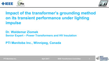
Page 6 of 81July 2005FIST 5-1PERSONAL PROTECTIVE GROUNDING FOR ELECTRIC POWER FACILITIESAND POWER LINESHigh-voltage lines and equipment shall be considered energized until protectivegrounds are installed. Until grounded, minimum approach distance applies.4.1 Electric Shock HazardIt is current through the body that causes electric shock or electrocution. Thepotential difference a person may contact between conductive parts of equipment orbetween equipment and ground is important because this voltage forces currentthrough the body according to Ohm’s law. Therefore, current through the bodyincreases with lower body resistance and also increases with higher contact voltage.Hazardous conditions may develop that place the worker’s body in series or parallelwith circuits that can produce a current through the body (figure 1). Personalprotective grounding is a special case of the parallel circuit where low-resistancegrounding cable is in parallel with the worker to shunt current away from the body.The accepted minimum value of body resistance is 500 ohms for electric shockhazard analysis. Although the resistance between hands with dry skin can rangefrom 5,000 to 50,000 ohms, punctured skin reduces the body resistance to about thatof salt water which is very low. Voltages above 240 volts readily penetrate dry skin,leaving a small, deep burn. Appendix A gives established criteria on the effects ofcurrent through the body.Figure 1. – Body Current Path.The maximum safe body current for short periods of time is given by Dalziel’sequation (appendix B) and is an inverse function of time. Higher currents arepermitted for shorter periods of time. Shock durations, or human exposure times fortemporary personal protective grounding applications are determined from typicalpower system fault clearing times as follows:
July 2005Page 7 of 81FIST 5-1PERSONAL PROTECTIVE GROUNDING FOR ELECTRIC POWER FACILITIESAND POWER LINES1) Thirty cycles (1/2 second) for transmission and distribution lines;2) Fifteen cycles (1/4 second) for switchyards and substations; or3) Fifteen cycles (1/4 second) for power and pumping plants.These fault clearing times are based on typical protective relaying and circuit breakeroperating times. Plants and switchyards generally are protected by high-speedcurrent differential relays with faster operating times compared to transmission linesemploying zone distance relaying. It is emphasized that these fault clearing timesare typical; grounding applications with known longer fault clearing times should beused in place of these typical values. However, shorter clearing times should not beused. Consult the TSC Hydroelectric Research and Technical Services Group ifdifferent fault clearing times appear necessary for a particular grounding application.Maximum safe body currents based on the above fault clearing times and the Dalzielequation are 200 milliamperes for 15 cycles and 150 milliamperes for 30 cycles (seederivation, appendix B). The resulting maximum safe body contact voltages are:15-cycle clearing 100 volts (200 mA); for plants, switchyards andsubstations30-cycle clearing 75 volts (150 mA); for transmission anddistribution lines4.2 Protective Grounding RequirementsEach region shall implement procedures to ensure the adequacy of protectivegrounds and shall periodically review grounding practices at each facility todetermine the proper size, length, and number (if parallel grounds are required) ofprotective grounds. Regions shall maintain and periodically update a listing of themaximum fault currents at each facility or location where Reclamation employeesapply protective grounds. These reviews should be conducted at 5-year intervals1 orsooner if change in equipment or system conditions call for specific revision.Protective ground cables and associated grounding equipment shall meet thefollowing requirements:1Refer to FIST Volume 4-1B, Maintenance Scheduling For Electrical Equipment, Section 25, April 2001
Page 8 of 81July 2005FIST 5-1PERSONAL PROTECTIVE GROUNDING FOR ELECTRIC POWER FACILITIESAND POWER LINES1) Capable of conducting the maximum fault current which could occur at thegrounded worksite if the de-energized line or equipment becomes energizedfrom any source and for the fault clearing times stated in paragraph 4.1.A ground or jumper which is sized to conduct maximum available faultcurrent should be adequate to safely conduct currents from othersources of hazardous energy stated in Section 3, including steady-statecurrents induced by electromagnetic coupling from nearby energizedlines or equipment.2) Capable of carrying the maximum available fault current, including dc offsetcurrent due to waveform asymmetry for high values of fault circuit impedanceX/R ratio. Refer to Section 5 for cable ampacity information and Section 6 forconductor sizing procedure.3) Capable of withstanding a second energization within 30 cycles after a firstinadvertent energization (paragraph 6.2.1).4) Applied at the worksite in a manner that the worker exposure or body contactvoltage does not exceed the values given in paragraph 4.1 while the groundcables are conducting fault current. Refer to Section 6 for procedure todetermine worker exposure voltage.5) Connected directly to the equipment, bus, or conductor to be grounded. Noimpedance or device (circuit breaker, disconnect switch, transformer, line trap,etc.) shall be permitted in series between the point of connection of theprotective grounds and location of contact by the workers.6) Be easy to apply, satisfy the requirements of field application conditions,utilize minimum time and preparation for installation, and cover a wide range ofusefulness. Standardization, to the extent practical, is desirable at each locationto keep the number of sizes and types to a minimum.7) Fabricated as an assembly of suitably rated components (conductor, ferrules,clamps) to withstand thermal and electro-mechanical stresses imposed whileconducting fault current (Section 5).8) Stored and transported properly to avoid damage and maintained in goodworking order (Section 10).9) Equipment and line terminal ground switches shall not be substituted forpersonal protective grounds. However, ground switches may be closed in
July 2005Page 9 of 81FIST 5-1PERSONAL PROTECTIVE GROUNDING FOR ELECTRIC POWER FACILITIESAND POWER LINESparallel with protective grounds to reduce fault current through the groundcables and lower the worker exposure voltage at the worksite. Ground cablesmust be sized for the maximum available fault current, without benefit of anyreduction in current due to closed ground switches.Some types of ground switches are designed for static grounding ofequipment and will not carry fault current. Check ground switchratings before closing in parallel with protective grounds. See also thecaution for closing ground switches into generators and motor,Section 7.10) Temporary removal of protective grounds for testing de-energizedequipment not permitted. Rather, protective grounds shall be installed in amanner that allows de-energized equipment under test to be safely isolated fromprotective grounded circuit(s) for the durati
equipment to earth or other conductive medium (grounding system) that substitutes for earth, e.g. station ground mat conductors. Grounded worksite. A work area that is made an equipotential safe working zone by the application of personal protective grounds. Personal protective g