Transcription
Surge Protective DevicesSTV100K Series
Safety InformationImportant InformationRead these instructions carefully and look at the equipment to becomefamiliar with the device before trying to install, operate, service or maintain it.The following special messages may appear throughout this bulletin or on theequipment to warn of potential hazards or to call attention to information thatclarifies or simplifies a procedure.The addition of either symbol to a “Danger” or “Warning” safety labelindicates that an electrical hazard exists which will result in personalinjury if the instructions are not followed.This is the safety alert symbol. It is used to alert you to potentialpersonal injury hazards. Obey all safety messages that follow thissymbol to avoid possible injury or death.DANGERDANGER indicates a hazardous situation which, if not avoided,will result in death or serious injury.WARNINGWARNING indicates a hazardous situation which, if not avoided,could result in death or serious injury.CAUTIONCAUTION indicates a hazardous situation which, if not avoided,could result in minor or moderate injury.NOTICENOTICE is used to address practices not related to physical injury. The safetyalert symbol shall not be used with this signal word.Please NoteElectrical equipment should be installed, operated, serviced, and maintained onlyby qualified personnel. No responsibility is assumed by Appleton Grp LLC d/b/aAppleton Group for any consequences arising out of the use of this material.A qualified person is one who has skills and knowledge related to theconstruction, installation, and operation of electrical equipment and has receivedsafety training to recognize and avoid the hazards involved.
STV100KPrecautionsDANGERHAZARD OF ELECTRIC SHOCK, EXPLOSION, OR ARC FLASH Apply appropriate personal protective equipment (PPE) and follow safe electrical work practices. See NFPA 70E,NOM-029-STPS or CSA Z462. This equipment must only be installed and serviced by qualified electrical personnel. Turn off all power supplying this equipment before working on or inside equipment. Always use a properly rated voltage sensing device to confirm power is off. Replace all devices, doors and covers before turning on power to this equipment. This equipment must be effectively grounded per all applicable codes. Use an equipment-grounding conductor toconnect this equipment to the power system ground. Do not install in areas with excessive dust, corrosive vapors, flammable materials, or explosive atmospheres.Failure to follow these instructions will result in death or serious injury.W ARNING: This product can expose you to chemicals including DINP, which is known to the State ofCalifornia to cause cancer, and DIDP which is known to the State of California to cause birth defects orother reproductive harm. For more information go to: www.P65Warnings.ca.gov.NOTICELOSS OF BRANCH CIRCUIT POWER / LOSS OF SURGE SUPPRESSION Perform periodic inspection of the surge protective device status indicator lights as part of the preventativemaintenance schedule. Promptly replace the surge protective device when an alarm state exists. Use dry contacts to signal an alarm state to the central supervisory system for unmanned, inaccessible, orcritical installations. Use multiple surge protective devices to achieve redundancy for critical applications.Failure to follow these instructions can result in equipment damage.At end-of-life conditions, Surge Protective Devices (SPDs) can lose their ability to suppress power systemtransient voltage spikes and attempt to draw excessive current from the line. This SPD is equipped withovercurrent and overtemperature components that will automatically disconnect the surge suppressionelements from the mains should the surge suppression elements reach end of life. Tripping of the branchcircuit breaker or fuse feeding the SPD can occur. Mitigate the tripping of the branch circuit breaker or fusefeeding the SPD by coordinating the surge suppression elements with the branch circuits.Page: 1
STV100KDANGERHAZARD OF ELECTRIC SHOCK, EXPLOSION, OR ARC FLASH Do not energize the surge protective device until the electrical system is completely installed, inspected andtested. Ensure all conductors are connected and functional. Verify the voltage rating of the device and system prior to energizing. Perform high-potential insulation testing, or any other tests where surge protective device components will besubjected to voltages higher than their rated turn-on voltage, with the neutral and surge protective device disconnected from the power sourceFailure to follow these instructions will result in death or serious injury.IntroductionDANGERHAZARD OF ELECTRIC SHOCK, EXPLOSION, OR ARC FLASH Apply appropriate personal protective equipment (PPE) and follow safe electrical work practices. See NFPA 70E,NOM-029-STPS or CSA Z462. This equipment must only be installed and serviced by qualified electrical personnel. Turn off all power supplying this equipment before working on or inside equipment. Always use a properly rated voltage sensing device to confirm power is off. Replace all devices, doors and covers before turning on power to this equipment. This equipment must be effectively grounded per all applicable codes. Use an equipment-grounding conductor toconnect this equipment to the power system ground.Failure to follow these instructions will result in death or serious injury.The SolaHD STV100K surge protective device is a surge current diversion system designed for use withequipment that is sensitive to damaging transient voltage surges.Page: 2
STV100KInstallation DANGERHAZARD OF ELECTRIC SHOCK, EXPLOSION, OR ARC FLASH Apply appropriate personal protective equipment (PPE) and follow safe electrical work practices. See NFPA 70E,NOM-029-STPS or CSA Z462. This equipment must only be installed and serviced by qualified electrical personnel. Turn off all power supplying this equipment before working on or inside equipment. Always use a properly rated voltage sensing device to confirm power is off. Replace all devices, doors and covers before turning on power to this equipment. All wiring must comply with theNational Electrical Code (NEC) and applicable local codes. This equipment must be effectively grounded per all applicable codes. Use an equipment-grounding conductor toconnect this equipment to the power system ground. For proper operation, neutral and ground must be reliably connected. Improper grounding will reduce or impedeoperation, and may result in damage to the SPD. Confirm that the Surge Protective Device voltage rating on the module or nameplate label is not less than theoperating voltage.Failure to follow these instructions will result in death or serious injury.Read all instructions before starting the installation of this product. These instructions do not replace nationalor electrical codes.The SolaHD STV100K Series Surge Protective Device is a high-quality, high-energy surge current diversionsystem designed to help protect sensitive equipment from damaging transient voltage surges resulting fromload switching, lightning strikes, and other sources.The installer should perform the following steps to ensure a quality installation. Please read all instructionsbefore starting the installation of this product.EnvironmentThe unit is designed for operation indoors in an ambient temperature range of -40 C to 50 C (-40 F to 122 F), with a relative humidity of 0% to 95% non-condensing.The unit is provided in a NEMA 12 metallic industrial enclosure. Do not install in areas with excessive dust,corrosive vapors, flammable materials, or explosive atmospheres.NOTICELOSS OF SURGE SUPPRESSION Do not install in areas with excessive dust, corrosive vapors, flammable materials, or explosive atmospheres.Failure to follow these instructions can result in equipment damage.MountingMount the unit as close as possible to the service panel. The unit should be positioned so that the length of thewiring to the surge protective device (SPD) is minimized. Use #10 (NEMA 12) mounting hardware.Page: 3
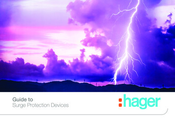
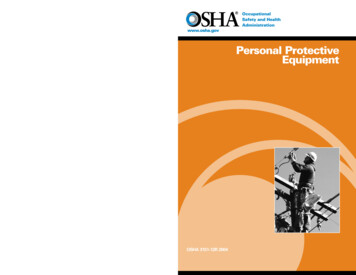
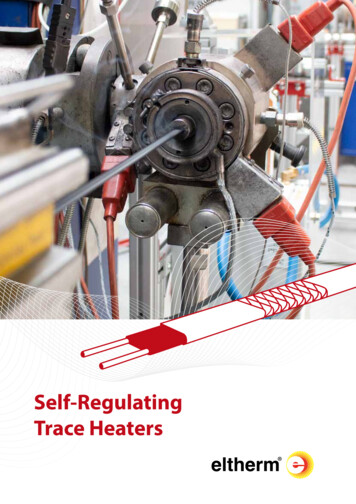
STV100KSPD TypeThe STV 100K series are Type 2 SPDs.Mechanical DimensionsFigure 1: Mechanical Dimensions (in.)Unit shown is a three-phase wyeVoltage Protection Ratings (VPRs)To maintain the voltage protection ratings, #12 AWG wire must be utilized to connect the STV100K Series toyour facility’s power grid.Wire Sizing/RoutingPhase, N, and GND wires are #12 AWG. NO, NC, and COM relay wires are #18 AWG. To reduce the wiringimpedance to surge currents, we recommend the phase, neutral (if required), and ground conductors to betwisted together and routed in the same raceway (conduit). Avoid any sharp bends in the conductors. Allwiring must comply with the National Electrical Code (NEC ), Canadian Electrical Code (CEC) and applicablelocal codes.DANGERHAZARD OF ELECTRIC SHOCK, EXPLOSION, OR ARC FLASH Do not supply more than 24VDC / 24VAC and no more than a current of 2 A to contacts. Confirm that the Surge Protective Device voltage rating on the module or nameplate label is not less than theoperating voltage.Failure to follow these instructions will result in death or serious injury.Page: 4
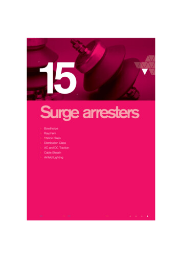
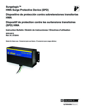
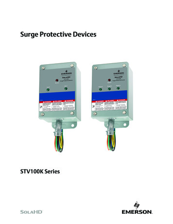
STV100KWiring ConnectionsBefore making connections to the unit, verify that the unit model numberand nameplate voltage rating are appropriate for connection to the intendedpower source. See Table 1 for voltage rating applications with typical powersource configurations.1. Turn off all power supplying this equipment before working on or insideequipment.2. It is recommended that a 20A circuit breaker be used for installation andconnection to the service panel.3. Connect the white neutral wire of the SPD (if provided) to the neutral ofthe supply. Connect the green ground wire of the SPD to source ground.4. Connect each Black Phase Wire to corresponding phase on the servicepanel. For delta high leg units, ensure the high leg is connected to phaseB of the SPD so they do not interfere with proper operation.5. If you are not using the relay contacts for remote sensing, cut andinsulate the orange COM wire, the blue NC wire, and the yellowNO wire in the conduit. For remote sensing, wires are connected toCOM, NC, and NO respectively.6. Replace the barrier, cover/door and/or trim to the equipment.7. Equipment may be re-energized after all the above steps are complete.Figure 2: Wiring connectionsNOTES: Figure 2 is a three-phase wye. A three-phase delta will have no neutral wire. For a three-phase delta highleg, Phase B will be the high leg. A split phase unit will have no Phase C and can be labeled Line 1 andLine 2. A single-phase L-N unit will have one black phase wire, a white neutral wire, and a green ground wire. Asingle-phase L-L unit will have two black phase wires and the green ground wire. Summary alarm Form C (1 NO and 1 NC) relay contacts may be provided for remote indication of a lossof surge protection. This indication may also consist of a phase loss or undervoltage condition. Summary alarm Form C relay contacts are rated 5 A at 125 VAC maximum with a power factor of 1.0. Forunits with Summary Alarm Contacts, access to the contacts are provided via #18 AWG wires (yellow NO,orange COM, and blue NC).Applying PowerApply power to the SPD and ensure status indications are normal. Under normal conditions, the green LEDsare illuminated and the red “Service” LED is extinguished. If normal status indication does not exist, see“Troubleshooting.”Page: 5
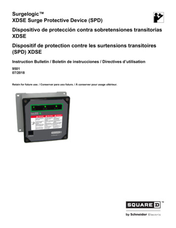
STV100KDANGERHAZARD OF ELECTRIC SHOCK, EXPLOSION, OR ARC FLASH The high-leg of the power system must connect to the B phase lug of the SPD.Failure to follow these instructions will result in death or serious injury.Table 1: Voltage Ratings & Power Source ConfigurationsModel: STV100K-10NNominal Voltage: 120 VSingle-phase, 2W GModel: STV100K-24LNominal Voltage: 240 VSingle-phase, 2W GModel: STV100K-10SNominal Voltage: 120/208–240 VSingle-phase, 3W GModel: STV100K-24DNominal Voltage: 240 VModel: STV 100K-48DNominal Voltage: 480 VPage: 6Three-phase delta, 3W G
STV100KTable 1: Voltage Ratings & Power Source ConfigurationsModel: STV100K-10YNominal Voltage: 120/208 VModel: STV100K-23YNominal Voltage: 230/400 VModel: STV100K-27YNominal Voltage: 277/480 VThree-phase wye, 4W GModel: STV 100K-10D4Nominal Voltage: 120/240 VThree-phase delta high leg, 4W GModel: STV 100K-24D4Nominal Voltage: 240/480 VTroubleshootingIf any of the diagnostic indicators indicate a problem (e.g., red “Service” LED on and/or green LEDs off),check all connections and voltages to the unit.If all connections are made and reliable, and proper voltages are supplied to the unit, contact SolaHDTechnical Support at (800) 377-4384/(847) 268-6651 or by e-mail at e refer to the “Terms & Conditions of Sale” document or visit www.solahd.com.Technical SupportWebsite: www.solahd.comTechnical Support E-Mail: solahd.technicalservices@emerson.comToll-Free: (800) 377-4384USA: (847) 268-6651While every precaution has been taken to ensure accuracy and completeness in this manual, Appleton Grp LLC d/b/a Appleton Groupassumes no responsibility, and disclaims all liability for damages resulting from use of this information or for any errors or omissions.Page: 7
STV100KSpecificationsTable 2: Technical TV100K10SSTV100K10YSTV100K23YNominal Input Voltage120 V240 V120/208–240 V120/208 V230/400 VSystem Configuration1-phase2W G1-phase2W G1-phase3W G3-phase wye 4W G3-phase wye 4W GMaximum Continuous OperatingVoltage (MCOV)150Vpk320Vpk150Vpk150Vpk320VpkLine Frequency47–63 HzResponse Time 0.5 nsSCCR Rating100 kAThermal and fault currentFusing20 kANominal Discharge Current Rating-40 C to 50 C (-40 F to 122 F)Operating Temperature0 to 95% non-condensingOperating Humidity40 dBA maximumNoise Attenuation6.00 in. x 4.00 in. x 3.20 in. (152.4 mm x 101.6 mm x 81.28 mm)Dimensions, W x D x H8.0 lb. (3.63 kg)Net WeightMetal, NEMA 12 ng TypeRed and green LED status indicators, audible alarm, Form C contactsStatus IndicationcULus Listed: UL 1449, CSA C22.2 No. 269.2Standard Certifications10 yearsWarrantyType 2 Voltage Protection Ratings600 VN/A600 V600 V1200 VN/A1000 V1000 V1000 V1800 VLine to Ground700 V1200 V700 V700 V1200 VNeutral to Ground600 VN/A600 V600 V1200 VN/AN/AN/AN/AN/ALine to NeutralLine to LineHigh Leg to NeutralHigh Leg to LineN/AN/AN/AN/AN/AHigh Leg to GroundN/AN/AN/AN/AN/APeak Surge Current CapabilityPer Phase100 kA100 kA100 kA100 kA100 kALine to Neutral50 kAN/A50 kA50 kA50 kAN/A50 kA50 kA50 kA50 kALine to Ground50 kA50 kA50 kA50 kA50 kANeutral to Ground50 kAN/A50 kA50 kA50 kALine to LinePage: 8
STV100KTable 2: Technical SpecificationsModelParametersNominal Input VoltageSystem ConfigurationMaximum Continuous OperatingVoltage (MCOV)STV100K27YSTV100K24DSTV100K48D277/480 V240 V480 V3-phase wye 4W G320Vpk3-phase delta 3W G 3-phase delta 3W G320VpkSTV100K10D4120/240 V240/480 V3-phase delta highleg4W G3-phase delta highleg4W G150/320Vpk320/550Vpk550VpkLine Frequency47–63 HzResponse Time 0.5 nsSTV100K24D4100 kASCCR RatingThermal and fault currentFusing20 kANominal Discharge Current Rating-40 C to 50 C (-40 F to 122 F)Operating Temperature0 to 95% non-condensingOperating Humidity40 dBA maximumNoise Attenuation6.00 in. x 4.00 in. x 3.20 in. (152.4 mm x 101.6 mm x 81.28 mm)Dimensions, W x D x H8.0 lb. (3.63 kg)Net WeightMetal, NEMA 12 ng TypeRed and green LED status indicators, audible alarm, Form C contactsStatus IndicationcULus Listed: UL 1449, CSA C22.2 No. 269.2Standard Certifications10 yearsWarrantyType 2 Voltage Protection RatingsLine to Neutral1200 VN/AN/A600 V1200 VLine to Line1800 V1000 V2000 V1000 V1800 VLine to Ground1200 V1200 V1800 V700 V1200 VNeutral to Ground1000 VN/AN/A600 V1200 VHigh Leg to NeutralN/AN/AN/A1200 V1800 VHigh Leg to LineN/AN/AN/A1200 V1800 VHigh Leg to GroundN/AN/AN/A1800 V3000 V100 kA100 kA100 kAPeak Surge Current CapabilityPer Phase100 kA100 kALine to Neutral50 kAN/AN/A50 kA50 kALine to Line50 kA50 kA50 kA50 kA50 kALine to Ground50 kA50 kA50 kA50 kA50 kANeutral to Ground50 kAN/AN/A50 kA50 kAPage: 9
STV100K SeriesA272-330 Rev. 0 12/2020The Emerson logo is a trademark and service mark of Emerson Electric Co.Appleton Grp LLC d/b/a Appleton Group. SolaHD is a registered trademark of Appleton Grp LLC.All other marks are the property of their respective owners. 2020 Emerson Electric Co. All rights reserved.United States(Headquarters)Appleton Grp LLC9377 W. Higgins RoadRosemont, IL 60018United StatesT 1 800 621 1506EuropeATX SASEspace Industriel Nord35, rue André Durouchez,CS 9801780084 Amiens Cedex 2FranceT 33 3 2254 1390CanadaEGS Electrical Group CanadaLtd.99 Union StreetElmira ON, N3B 3L7CanadaT 1 888 765 2226Asia PacificEGS Private Ltd.Block 4008, Ang Mo KioAve 10,#04-16 TechPlace 1,Singapore 569625T 65 6556 1100Latin AmericaEGS ComercializadoraMexico S de RL de CVCalle 10 N 145 Piso 3Col. San Pedro de los PinosDel. Álvaro ObregonCiudad de México. 01180T 52 55 5809 5049Australia Sales OfficeBayswater, VictoriaT 61 3 9721 0348China Sales OfficeShanghaiT 86 21 3338 7000Middle East Sales OfficeDammam, Saudi ArabiaT 966 13 510 3702Chile Sales OfficeLas CondesT 56 2928 4819India Sales OfficeChennaiT 91 44 3919 7300Korea Sales OfficeSeoulT 82 2 3483 1555PN# 9682 r-
Apply appropriate personal protective equipment (PPE) and follow safe electrical work practices. See NFPA 70E, NOM-029-STPS or CSA Z462. This equipment must only be installed and serviced by qualified electrical personnel. Turn off all power supplying this equipment