Transcription
Surgelogic XDSE Surge Protective Device (SPD)Dispositivo de protección contra sobretensiones transitoriasXDSEDispositif de protection contre les surtensions transitoires(SPD) XDSEInstruction Bulletin / Boletín de instrucciones / Directives d’utilisation950107/2018Retain for future use. / Conservar para uso futuro. / À conserver pour usage ultérieur.
XDSE Surge Protective Device (SPD)ENGLISHTable of ContentsPrecautions . 3Introduction . 4Unpacking and Preliminary Inspection . 5Storage . 5Identification Nameplate . 5SPD Location Considerations . 5Environment . 5Audible Noise . 5Mounting . 5Service Clearance . 5Equipment Performance . 5Electrical . 6Voltage Rating . 6Branch Circuit Overcurrent Protection and Disconnect Means . 7Location of Surge Protective Device (SPD) . 7System Grounding . 8Wiring . 9XDSE Wiring Diagrams . 11Installation . 13Surface Mount Installation . 13Flush Mount Installation. 14Operation . 14LED Status Indicators . 15Audible Alarm . 15Dry Contacts . 15Remote Monitor Option . 16Preventive Maintenance . 172 2018 Schneider ElectricAll Rights Reserved / Reservados todos los derechos / Tous droits réservés9501
PrecautionsXDSE Surge Protective Device (SPD)PrecautionsDANGERENGLISH950107/2018HAZARD OF ELECTRIC SHOCK, EXPLOSION, OR ARC FLASH Apply appropriate personal protective equipment (PPE) and follow safeelectrical work practices. See NFPA 70E, NOM-029-STPS orCSA Z462. This equipment must only be installed and serviced by qualifiedelectrical personnel. Turn off all power supplying this equipment before working on or insideequipment. Always use a properly rated voltage sensing device to confirm power is off. Replace all devices, doors and covers before turning on power to thisequipment. This equipment must be effectively grounded per all applicable codes.Use an equipment-grounding conductor to connect this equipment tothe power system ground.Failure to follow these instructions will result in death or serious injury.CAUTIONNOTICELOSS OF BRANCH CIRCUIT POWER / LOSS OF SURGESUPPRESSION Perform periodic inspection of the surge protective device statusindicator lights as part of the preventative maintenance schedule. Promptly replace the surge protective device when an alarm stateexists. Use dry contacts to signal an alarm state to the central supervisorysystem for unmanned, inaccessible, or critical installations. Use multiple surge protective devices to achieve redundancy for criticalapplications.Failure to follow these instructions can result in equipment damage.At end-of-life conditions, Surge Protective Devices (SPDs) can lose theirability to suppress power system transient voltage spikes and attempt todraw excessive current from the line. This SPD is equipped with overcurrentand overtemperature components that will automatically disconnect thesurge suppression elements from the mains should the surge suppressionelements reach end of life. Tripping of the branch circuit breaker or fusefeeding the SPD can occur. Mitigate the tripping of the branch circuitbreaker or fuse feeding the SPD by coordinating the surge suppressionelements with the branch circuits. 2018 Schneider Electric USA, Inc. All Rights ReservedFor troubleshooting, call the Surgelogic Technical Assistance Group at 1-800-577-7353.3
XDSE Surge Protective Device (SPD)Introduction950107/2018ENGLISHCAUTIONLOSS OF SURGE SUPPRESSION Do not energize the surge protective device until the electrical system iscompletely installed, inspected and tested. Ensure all conductors are connected and functional. Verify the voltage rating of the device and system prior to energizing. Perform high-potential insulation testing, or any other tests where surgeprotective device components will be subjected to voltages higher thantheir rated turn-on voltage, with the neutral and surge protective devicedisconnected from the power source.Failure to follow these instructions can result in injury or equipmentdamage.IntroductionDANGERHAZARD OF ELECTRIC SHOCK, EXPLOSION, OR ARC FLASH Apply appropriate personal protective equipment (PPE) and follow safeelectrical work practices. See NFPA 70E, NOM-029-STPS orCSA Z462. This equipment must only be installed and serviced by qualifiedelectrical personnel. Turn off all power supplying this equipment before working on or insideequipment. Always use a properly rated voltage sensing device to confirm power is off. Replace all devices, doors and covers before turning on power to thisequipment. This equipment must be effectively grounded per all applicable codes.Use an equipment-grounding conductor to connect this equipment tothe power system ground.Failure to follow these instructions will result in death or serious injury.Note: For troubleshooting, call the SurgelogicTechnical Assistance Group at 1-800-577-7353.4Proper installation is imperative to maximize the XDSE SPD’s effectivenessand performance. Follow the steps outlined in this instruction bulletin toensure proper installation. Read the entire instruction bulletin beforebeginning the installation. These instructions are not intended to replacenational or local electrical codes. Check all applicable electrical codes toverify compliance. Installation of XDSE surge suppressors must only beperformed by qualified electrical personnel. 2018 Schneider Electric USA, Inc. All Rights ReservedFor troubleshooting, call the Surgelogic Technical Assistance Group at 1-800-577-7353.
XDSE Surge Protective Device (SPD)950107/2018StorageIdentification NameplateInspect the entire shipping container for damage or signs of mishandlingbefore unpacking the device. Remove the packing material and furtherinspect the device for any obvious shipping damage. If any damage is foundand is a result of shipping or handling, immediately file a claim with theshipping company.The device should be stored in a clean, dry environment. Storagetemperature is -40 F to 140 F (-40 C to 60 C). All of the packagingmaterials should be left intact until the device is ready for installation.The identification nameplate is located on the side of the unit.Figure 1:XDSE Nameplate ExampleSPD LocationConsiderationsEnvironmentThe device is designed to operate in an ambient temperature range of-4 F to 140 F (-20 C to 60 C) with a relative humidity of 0 to 95%non-condensing. This device has a Type 4X housing.Audible NoiseThe device background noise is negligible and does not restrict the locationof the installation.MountingThe device has been designed to be surface mounted. An additionalflushmount kit is also available if required (XDSEMKF).Service ClearanceThe service clearance should meet all applicable code requirements.Equipment PerformanceTo obtain optimum surge suppression, locate the SPD as close as possibleto the circuitry being surge-limited to minimize the wire length. Minimizingthe wire length reduces the impedance between the circuitry and the SPD.Refer to the Voltage Protection Rating (VPR) values on the SPD nameplate.These VPR values were obtained by testing the SPD with six-inch longleads (per UL1449). For every additional foot of wire beyond six inches, theeffective VPR increases by approximately 160 volts. 2018 Schneider Electric USA, Inc. All Rights ReservedFor troubleshooting, call the Surgelogic Technical Assistance Group at 1-800-577-7353.5ENGLISHUnpacking and PreliminaryInspectionUnpacking and Preliminary Inspection
XDSE Surge Protective Device HAZARD OF ELECTRIC SHOCK, EXPLOSION, OR ARC FLASHConfirm the surge protective device voltage rating on the module ornameplate label is not less than the operating voltage.Failure to follow these instructions can result in death or serious injury.Voltage RatingPrior to mounting the SPD, verify that the device has the same voltagerating as the power distribution system in which it is installed. Compare thenameplate voltage or model number on the SPD with the nameplate of theelectrical distribution equipment.The specifier or user of the device should be familiar with the configurationand arrangement of the power distribution system in which the SPD is to beinstalled. The system configuration of any power distribution system isbased strictly on how the secondary windings of the transformer supplyingthe service entrance main or load are configured. This includes whether ornot the transformer windings are referenced to earth via a groundingconductor. The system configuration is not based on how any specific loador equipment is connected to a particular power distribution system. SeeTable 1 for the service voltage of each SPD.Table 1:XDSE Voltage RatingsService Voltage120/240 V,1 phase, 3-wire ground208Y/120 V,3 phase, 4-wire ground 2240/120 V,3 phase, (high-leg delta)4-wire ground480Y/277 V,3 phase, 4-wire ground 3480 V Delta,3 phase, 3-wire ground 4240 V Delta,3 phase, 3-wire ground600Y/347 V,3 phase, 4-wire ground600 V Delta,3 phase, 3 wire ground 516Peak Surge CurrentRating Per PhaseCatalog Number 1100 kASSP01XDSE10A150 kASSP01XDSE15A200 kASSP01XDSE20A100 kASSP02XDSE10A150 kASSP02XDSE15A200 kASSP02XDSE20A100 kASSP03XDSE10A150 kASSP03XDSE15A200 kASSP03XDSE20A100 kASSP04XDSE10A150 kASSP04XDSE15A200 kASSP04XDSE20A100 kASSP05XDSE10A150 kASSP05XDSE15A200 kASSP05XDSE20A100 kASSP06XDSE10A150 kASSP06XDSE15A200 kASSP06XDSE20A100 kASSP08XDSE10A150 kASSP08XDSE15A200 kASSP08XDSE20A100 kASSP09XDSE10AFor Type 1 systems include a "1" at the end of the catalog numbers listed above.2208Y/120 series also applies to the following voltage 220Y/127.3480Y/277 series also applies to the following voltages 380Y/220, 400Y/230, 415Y/240.4480 V Delta series also applies to the following voltages: 480Y/277V HRG.5600 V Delta series also applies to the following voltages: 600Y/347V HRG. 2018 Schneider Electric USA, Inc. All Rights ReservedFor troubleshooting, call the Surgelogic Technical Assistance Group at 1-800-577-7353.
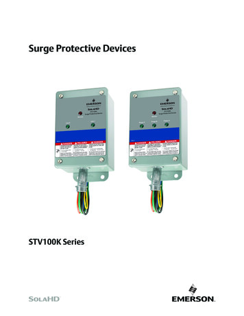
XDSE Surge Protective Device (SPD)950107/2018ElectricalBranch Circuit OvercurrentProtection and Disconnect MeansENGLISHDANGERHAZARD OF ELECTRIC SHOCK, EXPLOSION, OR ARC FLASH Use conductors rated for the Overcurrent Protection Device (OCPD) perapplicable codes. Use conductors rated for the application per applicable codes.Failure to follow these instructions will result in death or serious injury.A branch circuit Overcurrent Protection Device (OCPD) either in the form ofa circuit breaker or fuse must be provided for the XDSE Type 2 device. Thebranch circuit OCPD should either provide or include a disconnectingmeans.Since the current drawn by the XDSE device during normal operation isnegligible, the XDSE device can be connected to a dedicated, separatebranch circuit or connected to a suitable existing branch circuit.When connected to a separate, dedicated branch circuit, the OCPD settingmust be selected to protect the conductors feeding the XDSE device perapplicable state and local building codes.Location of Surge ProtectiveDevice (SPD)UL 1449 Type 1 SPDs have been designed and approved for line sideapplications prior to the main service disconnect without supplementalovercurrent protection. Type 2 SPDs must be installed on the load side ofthe main Overcurrent Protective Device (OCPD). All installations shouldeither provide or include a disconnecting means.Type 1 SPDs can also be used in Type 2 applications (load side of OCPD).When either Type 1 or Type 2 SPDs are used on the load side, they must beinstalled per local codes.Locate the SPD as close as possible to the circuit mains being surge-limitedto minimize the wire length and optimize SPD performance. Avoid long wireruns so that the device will perform as intended. To reduce the impedancethat the wire displays to surge currents, the phase, neutral, and groundconductors (wye and high-leg delta configurations), or phase and groundconductors (delta configurations), must be routed within the same conduitand tightly bundled or twisted together to optimize device performance.Avoid sharp bends in the conductors. See Figures 2 and 3.Figure 2:SPD Wiring for Wye and High-Leg Delta ConfigurationsTo load(s)Phase APhase BPhasesPhase CNeutralNeutralNeutral busGroundGroundGround busSPDPanel 2018 Schneider Electric USA, Inc. All Rights ReservedFor troubleshooting, call the Surgelogic Technical Assistance Group at 1-800-577-7353.Interconnect wiring– Minimize length– Avoid sharp bends7
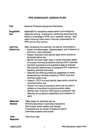
XDSE Surge Protective Device (SPD)System Grounding950107/2018Figure 3:SPD Wiring for Delta ConfigurationsENGLISHTo load(s)Phase APhase BPhase CPhasesGroundGroundSPDInterconnect wiring– Minimize length– Avoid sharp bendsSystem GroundingUngrounded power systems are inherently unstable and can produceexcessively high line-to-ground voltages during certain fault conditions.During these fault conditions any electrical equipment, including a surgeprotective device, may be subjected to voltages which exceed theirdesigned ratings. This information is being provided to the user so that aninformed decision can be made before installing any electrical equipment onan ungrounded power system.CAUTIONNOTICELOSS OF SURGE SUPPRESSION Verify that the service entrance equipment is bonded to ground inaccordance with all applicable codes.Failure to follow these instructions can result in equipment damage.The XDSE has SPD elements connected from phase to ground. It is criticalthat there be a robust and effective connection to the building groundingstructure. The grounding connection must utilize an equipment groundingconductor run with the phase and neutral connection of the power system.Do not connect the SPD to a separate isolated ground. For best voltagesuppression by the XDSE SPD, use a single-point ground system where theservice entrance grounding electrode system is connected to, and bondedto, all other available electrodes, building steel, metal water pipes, drivenrods, etc. (for reference, see NEC Art 250). The ground impedancemeasurement of the electrical system must be as low as possible and incompliance with all applicable codes for sensitive electronic and computersystems.8 2018 Schneider Electric USA, Inc. All Rights ReservedFor troubleshooting, call the Surgelogic Technical Assistance Group at 1-800-577-7353.
950107/2018XDSE Surge Protective Device (SPD)WiringENGLISHWARNINGNOTICEINADEQUATE RACEWAY ELECTRICAL CONTINUITY Install an insulated grounding conductor inside a metallic raceway whenthe raceway is used as an additional grounding conductor. Size theconductor in accordance with all applicable codes. Maintain adequate electrical continuity at all raceway connections. Do not use isolating bushings to interrupt a metallic raceway run. Do not use a separate isolated ground for the surge protective device. Verify proper equipment connections to the grounding system. Verify ground grid continuity by inspections and testing as part of acomprehensive electrical maintenance program.Failure to follow these instructions can result in equipment damage.WiringDANGERHAZARD OF ELECTRIC SHOCK, EXPLOSION, OR ARC FLASH Apply appropriate personal protective equipment (PPE) and follow safeelectrical work practices. See NFPA 70E, NOM-029-STPS orCSA Z462. This equipment must only be installed and serviced by qualifiedelectrical personnel. Turn off all power supplying this equipment before working on or insideequipment. Always use a properly rated voltage sensing device to confirm power is off. Replace all devices, doors and covers before turning on power to thisequipment. This equipment must be effectively grounded per all applicable codes.Use an equipment-grounding conductor to connect this equipment tothe power system ground. Confirm the surge protective device voltage rating on the module ornameplate label is not less than the operating voltage.Failure to follow these instructions will result in death or serious injury. 2018 Schneider Electric USA, Inc. All Rights ReservedFor troubleshooting, call the Surgelogic Technical Assistance Group at 1-800-577-7353.9
XDSE Surge Protective Device (SPD)WiringTable 2:Wiring Diagram Location1ENGLISHWiring for:Figure and PageSingle-phase, three-wire,grounded installationFigure 6 on page 11Single-phase, two-wire, ground, delta installationFigure 7 on page 11Three-phase, three- or four-wire,grounded WYE installationFigure 8 on page 12Three-phase, three- or four-wire,high-leg delta installationFigure 9 on page 12Three-phase, three-wire ground, delta installationFigure 10 on page 121See “Dry Contacts” on page 15 for dry contact wiring.950107/2018Follow steps 1 through 7 to make wiring connections:1. Turn off all power supplying this equipment before working on or inside anyenclosure containing this equipment.2. Confirm SPD is rated for your system by comparing voltage measurementsto the Line Voltage (L-L, L-N) on the product label.3. Identify proper location for the SPD. Locate as close as possible to themains of the panel being surge-limited so the wires are as short as possible.Mount unit securely.Note: The SPD must be installed in an accessible location (not within wallsunless surface mounted with the XDSEMKF flush mount kit).4. Install in accordance with national and local electrical codes and match thebranch circuit Overcurrent Protection Device (OCPD) to the wire size.5. Twist conductors 1/2 turn or more for every twelve inches of length.6. Do not loop or coil wires. Be sure to maintain adequate wire bending spaceper NEC.7. Use on solidly grounded systems unless the SPD model is designed forinstallation on ungrounded/HRG systems.Note: On a high-leg delta installation, the high-leg of the power systemmust be connected to the B phase lug of the SPD.WARNINGHAZARD OF ELECTRIC SHOCK, EXPLOSION, OR ARC FLASHFor outdoor installation use and appropriate weather sealing at the nipple(o-ring, sealing conduit, etc).Failure to follow these instructions can result in death or serious injury.Figure 4:Conduit InstallationIncorrect installationsCorrect installation:Threaded 6full turnsPoor engagement:Conduit needs to bethreaded in farther10Overtightened:Stresses box, only6 full turns required 2018 Schneider Electric USA, Inc. All Rights ReservedFor troubleshooting, call the Surgelogic Technical Assistance Group at 1-800-577-7353.
XDSE Surge Protective Device (SPD)950107/2018WiringTypical Panel InstallationENGLISHFigure 5:To protected loadsNote: Use closest circuit breakerto SPD. Locate SPD close to theintended circuit breaker.Note: Keep leads as short aspossible. Avoid sharp bends.Note: Rotate XDSE such thatthe LED indicator is most visible.XDSE Wiring DiagramsFigure 6:Single-Phase, Three-Wire, Grounded InstallationL1 BlackN WhiteACL2 BlackG GreenFigure 7:NGSingle-Phase, two-Wire, Delta InstallationL1 BlackL2 BlackG GreenACN 2018 Schneider Electric USA, Inc. All Rights ReservedFor troubleshooting, call the Surgelogic Technical Assistance Group at 1-800-577-7353.G11
XDSE Surge Protective Device (SPD)WiringENGLISHNote 1: The neutral conductor is not present onthree-wire Wye grounded power systems.For proper operation of the SPD diagnostics onthese systems, bond the neutral and ground lugstogether inside the SPD.950107/2018Figure 8:Three-Phase, three- or four-Wire, Grounded WYEInstallation 1BL1 BlackN WhiteL2 BlackANote 2: The high-leg of the power system mustconnect to the B phase lug of the SPD.The neutral conductor is not present onthree-wire High-Leg Delta grounded powersystems. For proper operation of the SPDdiagnostics on these systems, bond the neutraland ground lugs together inside the SPD.Figure 9:CNL3 BlackG GreenGThree-Phase, three- or four-Wire, High-Leg DeltaInstallation 2BL1 BlackL3 BlackACL2 BlackNN WhiteG GreenFigure 10:GThree-Phase, three-Wire, Delta InstallationBL1 BlackL2 BlackACL3 BlackG Green12G 2018 Schneider Electric USA, Inc. All Rights ReservedFor troubleshooting, call the Surgelogic Technical Assistance Group at 1-800-577-7353.
XDSE Surge Protective Device (SPD)950107/2018InstallationDANGERHAZARD OF ELECTRIC SHOCK, EXPLOSION, OR ARC FLASH Apply appropriate personal protective equipment (PPE) and follow safeelectrical work practices. See NFPA 70E, NOM-029-STPS orCSA Z462. This equipment must only be installed and serviced by qualifiedelectrical personnel. Turn off all power supplying this equipment before working on or insideequipment. Always use a properly rated voltage sensing device to confirm power is off. Replace all devices, doors and covers before turning on power to thisequipment. This equipment must be effectively grounded per all applicable codes.Use an equipment-grounding conductor to connect this equipment tothe power system ground.Failure to follow these instructions will result in death or serious injury.Surface Mount InstallationNote: Mount the unit as close as possible to the protected panel.1. Make perforations on the wall according to the screw holes located onthe enclosure. See Figure 11. (Rotate dimensions 90 as appropriatedepending on orientation).2. Configure the electrical conductor and conduit connection consistentwith the installation instructions on pages 9 through 13.3. Install faceplate/cover, applying a torque of 5 lb-in (0.5 N m) to the fourscrews, prior to energizing and testing the unit.Figure 11:General Ø 0.3(Ø 7.9)6.0(152.4)5.3(136.1)0.8 3.9(22.2) (99.7)3.4(86.6)3.4 in. (25.4 mm) Female NPT threadØ 1.0(Ø 25.4) 2018 Schneider Electric USA, Inc. All Rights ReservedFor troubleshooting, call the Surgelogic Technical Assistance Group at 1-800-577-7353.13ENGLISHWiring
XDSE Surge Protective Device (SPD)Wiring950107/2018Flush Mount InstallationNote: Mount the unit as close as possible to the protected panel.ENGLISH1. Create a wall opening 6 3/4 in. x 6 1/16 in. and 3 15/16 in. of clearance.See Figure 12. (Rotate dimensions 90 as appropriate depending onorientation).2. Configure an appropriate backing plate inside the wall cavity 3 15/16inches from the wall face such that the unit will be supported from itsback.3. Configure the electrical conductor and conduit connection consistentwith the installation instructions on pages 9 through 13. Preplanconnections such that they are completed prior to fastening the unit tothe backing plate.4. Install faceplate/cover, applying a torque of 5 lb-in (0.5 N m) to the fourscrews, prior to energizing and testing the unit.Figure 12:MountingplateFlush Mount6.75 in.(171 mm)Wall openingMounting plateinstalled3 15/16 in.(100 mm) fromthe front wall.FlexibleconduitStep 1:Prepare walland SPDStep 2:Insert intowallWall cutout 6 3/4 in.font view (171 mm)TallFlexibleconduitFlexibleconduitStep 3:Mount theSPD6 1/6 in.(154 mm)WideStep 4:Mountthe lidin.(mm)Note: Supplemental instructions for deep wall mounting (walls over 4 in. (101 mm) thick using the enclosed mounting feet.OperationDANGERHAZARD OF ELECTRIC SHOCK, EXPLOSION, OR ARC FLASH Apply appropriate personal protective equipment (PPE) and follow safeelectrical work practices. See NFPA 70E, NOM-029-STPS orCSA Z462. This equipment must only be installed and serviced by qualifiedelectrical personnel. Turn off all power supplying this equipment before working on or insideequipment. Always use a properly rated voltage sensing device to confirm power is off. Replace all devices, doors and covers before turning on power to thisequipment. This equipment must be effectively grounded per all applicable codes.Use an equipment-grounding conductor to connect this equipment tothe power system ground.Failure to follow these instructions will result in death or serious injury.14 2018 Schneider Electric USA, Inc. All Rights ReservedFor troubleshooting, call the Surgelogic Technical Assistance Group at 1-800-577-7353.
XDSE Surge Protective Device (SPD)950107/2018Diagnostic LEDs are located on the front of the XDSE SPD device. Theyoperate as follows: Verify that all phase voltages are present. If any of the LEDs are notilluminated, the device may not be installed correctly. Check the powersupply and service voltage. Upon energizing the SPD, check the LEDstatus. If all of the LEDs are illuminated, surge suppression is operating. If an inoperative condition occurs the device must be replaced byqualified electrical personnel.If one or more LEDs are not illuminated, there is a loss of surgesuppression on that phase.Figure 13:Diagnostic OperationIndicator light ON OKIndicator Light OFF loss of surge suppression onthat phase andaudible alarm ON Loss ofsurge suppresionIndicator light ON (red) loss of surge suppresionAudible AlarmThe audible alarm does not have a silence switch. Silence the alarm byremoving power from the SPD. The alarm indicates that the device needsreplacement by qualified electrical personnel.Dry ContactsCAUTIONINADEQUATE DRY CONTACT USEDo not supply more than 24 V dc / 24 V ac and no more than a currentof 2 A.Failure to follow these instructions can result in injury or equipmentdamage.The XDSE series SPD device is provided with dry contacts. The unpoweredstate shall be closed between the common wire and the normally closedwire. This is also the alarm condition. The opposite state, closed betweenthe common wire and the normally open wire, indicates that power is on tothe unit and that no alarm condition exists (See Table 3). These dry contactleads can be used for remote indication of the SPD operating status to acomputer interface board or emergency management system. Also, thesedry contact leads are designed to work with the SPD remote monitor optiondescribed in the following section. 2018 Schneider Electric USA, Inc. All Rights ReservedFor troubleshooting, call the Surgelogic Technical Assistance Group at 1-800-577-7353.15ENGLISHLED Status IndicatorsWiring
XDSE Surge Protective Device (SPD)Wiring950107/2018ENGLISHThe dry contacts are designed for a maximum voltage of 24 V dc / 24 V acand a maximum current of 2 A. Higher energy applications may requireadditional relay implementation outside the SPD. Damage to the SPD’srelay caused by use with energy levels in excess of those discussed in thisinstruction bulletin are not covered by warranty. For application questions,call the Surgelogic Technical Assistance Group at (800) 577-7353.Table 3:Remote Monitor OptionDry Contact ConfigurationDry Contact TerminalPower off or AlarmConditionPower on and no AlarmConditionN/O(Normally Open)OpenClosedCOMCommonCommonCommonN/CNormally ClosedClosedOpenThe remote monitor option has two LEDs, one red and one green, and anaudible alarm with an enable/disable switch. Normal status is a lit greenLED, and no audible alarm. To test the integrity of the remote monitor, pressthe push-to-test switch. The green LED will turn off, the red LED will turn on,and the alarm will sound, if the alarm is enabled. Releasing the switch willcomplete the test; the red LED will turn off, the green LED will turn on andthe alarm will shut off.If suppression on any phase is lost, the green LED will turn off, the red LEDwill illuminate and an alarm will sound. The audible alarm can be silenced bypushing the alarm enable/disable/test switch. The alarm will silence and thegreen alarm LED will not be lit. The re
Apply appropriate personal protective equipment (PPE) and follow safe electrical work practices. See NFPA 70E, NOM-029-STPS or CSA Z462. This equipment must only be installed and serviced by qualified electrical personnel. Turn off all power supplying this equipment