Transcription
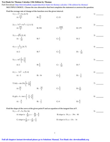
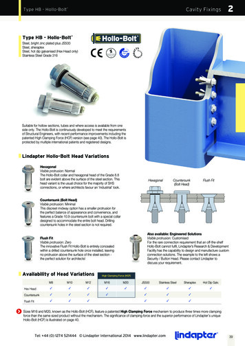
Type HB - Hollo-BoltCavity Fixings 2Hollo-BoltType HB - Hollo-Bolt Steel, bright zinc plated plus JS500Steel, sheraplexSteel, hot dip galvanised (Hex Head only)Stainless Steel Grade 316Suitable for hollow sections, tubes and where access is available from oneside only. The Hollo-Bolt is continuously developed to meet the requirementsof Structural Engineers, with recent performance improvements including thepatented High Clamping Force (HCF) version (see page 40). The Hollo-Bolt isprotected by multiple international patents and registered designs.Lindapter Hollo-Bolt Head VariationsHexagonalVisible protrusion: NormalThe Hollo-Bolt collar and hexagonal head of the Grade 8.8bolt are evident above the surface of the steel section. Thishead variant is the usual choice for the majority of SHSconnections, or where architects favour an ‘industrial’ look.HexagonalCountersunk(Bolt Head)Flush FitCountersunk (Bolt Head)Visible protrusion: MinimalThis discreet midway option has a smaller protrusion forthe perfect balance of appearance and convenience, andfeatures a Grade 10.9 countersunk bolt with a special collardesigned to accommodate the entire bolt head. Drillingcountersunk holes in the steel section is not required.Also available: Engineered SolutionsVisible protrusion: CustomisedFor the rare connection requirement that an off-the-shelfHollo-Bolt cannot fulfil, Lindapter’s Research & DevelopmentFacility has the capability to design and manufacture customconnection solutions. The example to the left shows aSecurity / Button Head. Please contact Lindapter todiscuss your requirement.Flush FitVisible protrusion: ZeroThe innovative Flush Fit Hollo-Bolt is entirely concealedwithin a drilled countersunk hole once installed, leavingno protrusion above the surface of the steel section the perfect solution for architects!Availability of Head VariationsHigh Clamping Force (HCF)M8M10M12M16M20JS500Stainless SteelSheraplexHot Dip Galv.Hex Head333333333Countersunk3333333Flush Fit333333Sizes M16 and M20, known as the Hollo-Bolt (HCF), feature a patented High Clamping Force mechanism to produce three times more clampingforce than the same sized product without the mechanism. The significance of clamping force and the superior performance of Lindapter’s uniqueHollo-Bolt (HCF) is illustrated on page 40.Tel: 44 (0) 1274 521444 Lindapter International 2014 www.lindapter.com39
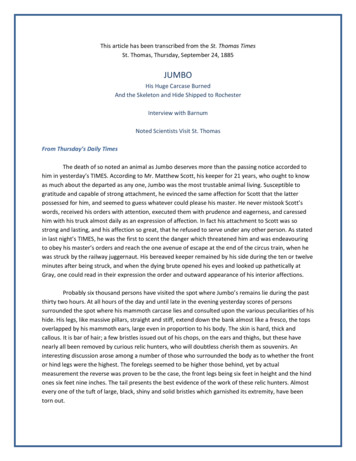
2Cavity FixingsHollo-Bolt Expansion MechanismHollo-Bolt & Hollo-Bolt (HCF)The Hollo-Bolt is available in two versions: the original 3-part designfor general hollow section connections and the larger sized 5-partHigh Clamping Force (HCF) version, for higher strength rtHollo-Bolt (HCF)Sleeve(legs expandduring installation)Bolt Clamping ForceM16M20High Clamping Force(HCF) MechanismCone(interlocking groovesprevent loosening)CollarHIGHCLAMPINGFORCECone(interlocking groovesprevent loosening)CollarSleeve(legs expandduring installation)Bolt Clamping Force3xCLAMPINGFORCE40A typical connection is made by inserting the Hollo-Bolt into thepre-drilled holes of the fixture and hollow section. As the bolt headis tightened, the cone is pulled up the bolt thread, causing the legsof the sleeve to expand until the cone locks the sleeve against theinner wall of the hollow section.Working closely with Structural Engineers & Steel Fabricators,Lindapter identified the need for the larger M16 & M20 Hollo-Boltsto have an increased clamping force suitable for higher strengthstructural connections. Research & Development led to the inventionof the patented 5-part design, optimised for superior performance.At full tightening torque, a clamping action is set up betweenthe fixture and steel section to form a secure connection. Onceinstalled, only the head and collar are visible.The High Clamping Force (HCF) mechanism consists of a specialwasher that ‘compresses’ to significantly increase clamping forcebetween the fixture and hollow section, when compared to a 3-partproduct of the same size, thereby reducing displacement.Tel: 44 (0) 1274 521444 Lindapter International 2014 www.lindapter.com
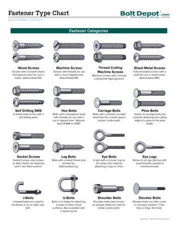
Cavity FixingsHollo-Bolt Clamping Force2Hollo-Bolt (HCF) - Typical Performance IncreaseHIGHCLAMPINGFORCE5-Part Design - With HCF Mechanism Hot Dip Galvanised, Size 23-Part Design - Without HCF Mechanism Hot Dip Galvanised, Size 2M20: Up to 3.5x Clamping Force707060605050Clamping Force (kN)Clamping Force (kN)M16: Up to 3x Clamping Force4030204030201010002040608010001200204060Time (minutes)80100120Time (minutes)Clamping ForceAs with any structural bolt, immediately after installation the bolt relaxes until a typical clamping force is reached. The typical clamping forceof the Hollo-Bolt (HCF) is over three times higher than the same sized product without the HCF mechanism. This results in a more secureconnection and a greater force that has to be overcome before displacement begins.M16 - Connection Load vs Ply DisplacementM20 - Connection Load vs Ply Displacement100140908012010060Load (kN)Load (kN)7050403080604020Safe Working Load10000.250.50.7511.251.51.7522.252.52.75Safe Working Load203000.250.50.751Displacement (mm)1.251.51.7522.252.52.753Displacement (mm)DisplacementThe significance of increased clamping force is shown in the graphs above. The blue curve demonstrates the superior performance of theHollo-Bolt (HCF) in contrast to M16 & M20 sized products without Lindapter’s patented HCF mechanism (i.e. the 3-part design). At SafeWorking Load, displacement (movement in the connection) is minimised when using the Hollo-Bolt (HCF) for a safer and more secure connection.Tel: 44 (0) 1274 521444 Lindapter International 2014 www.lindapter.com41
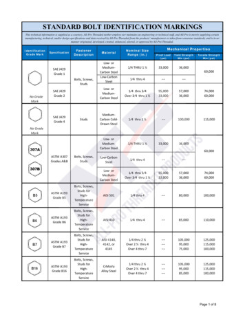
Cavity FixingsHollo-Bolt Design DataHollo-Bolt - Safe Working Loadsa) Hexagonalb) Countersunk (Bolt Head)Across FlatsHA/FLDdHigh Clamping Force Mechanism(Size M16 - M20)a) HEXAGONALdHmin tmin tb) COUNTERSUNKBoltLengthProductCodeBoltLengthmmHigh Clamping Force (HCF)WLDProductCodec) Flush FitWmmClampingThicknessOuterPlySleeveLengthOuter ØWmmmin tmmLmmHB08-1M8 x 50HBCSK08-1M8 x 503 - 22-30HB08-2M8 x 70HBCSK08-2M8 x 7022 - 41-49HB08-3M8 x 90HBCSK08-3M8 x 9041 - 60-68HB10-1M10 x 55HBCSK10-1M10 x 503 - 22-30HB10-2M10 x 70HBCSK10-2M10 x 7022 - 41-48HB10-3M10 x 90HBCSK10-3M10 x 9041 - 60-67HB12-1M12 x 60HBCSK12-1M12 x 553 - 25-35HB12-2M12 x 80HBCSK12-2M12 x 8025 - 47-57HB12-3M12 x 100HBCSK12-3M12 x 10047 - 69-79HB16-1M16 x 75HBCSK16-1M16 x 7012 - 29841.5HB16-2M16 x 100HBCSK16-2M16 x 10029 - 50863HB16-3M16 x 120HBCSK16-3M16 x 12050 - 71884HB20-1M20 x 90--12 - 34850HB20-2M20 x 120--34 - 60876HB20-3M20 x 150--60 - 868102HeightCollarØTighteningTorqueSafe Working Loads(5:1 Factor of Safety)dmmHmmDmmA/FmmNmTensilekNSingle 5.040.0Sizes M16 and M20, known as the Hollo-Bolt (HCF), feature a patented High Clamping Force mechanism to produce three times more clampingforce than the same sized product without the mechanism. The significance of clamping force and the superior performance of Lindapter’s uniqueHollo-Bolt (HCF) is illustrated on page 40.c) FLUSH terPlyLengthWmmmin tmmLmmHBFF08-1M8 x 5010 - 27835HBFF08-2M8 x 7027 - 45854HBFF08-3M8 x 9045 - 64873HBFF10-1M10 x 5012 - 271036HBFF10-2M10 x 7027 - 451054HBFF10-3M10 x 9045 - 641073HBFF12-1M12 x 5512 - 301042HBFF12-2M12 x 8030 - 521064HBFF12-3M12 x 10052 - mA/FmmNmTensilekNSingle 33308010.515.0Outer ØHeightdmmCollarSafe Working Loads(5:1 Factor of Safety)The Hollo-Bolt can be used on a wide variety of steel hollow shape sections; safe working loads shown are based on use in S275 structural hollowsection. The safe working loads, in both tension and shear, are applicable to the Hollo-Bolt only. Failure of the section, particularly on those with thinwalls and a wide chord face, could occur at a lower figure and its strength should be checked by a qualified Structural Engineer.The tables above state the safe working loads with a 5:1 Factor of Safety and should be used for secondaryapplications. For primary design, please consult the guide Joints in Steel Construction - Simple Connections.The guide provides design guidance for the use of Hollo-Bolt and gives essential information for structural steelworkconnections for use in buildings designed by the ‘Simple Method’ i.e. braced frames where connections carry mainlyshear and axial loads only. To obtain further details on the Simple Connections guide please contact:The Steel Construction Institute T: 44 (0) 1344 636 525 / F: 44 (0) 1344 636 570 / www.steel-sci.comPublished by SCI/BCSA Connections Group. Publication Number: P212 / ISBN 1 85942 072 9. Lindapter is a member of SCI and BCSA42Tel: 44 (0) 1274 521444 Lindapter International 2014 www.lindapter.com2
Cavity FixingsHollo-Bolt Design DataFor designingto Eurocode 3standard onlyHollo-Bolt Characteristic Values of Tensile and Shear Resistancetaken from ETA-10/0416 (www.lindapter.com/about/CE)Hollo-Bolt HexagonalHollo-Bolt Hexagonal Stainless SteelNominalSizeTensileFt,RkkNShearFv,RkkNMaterial Strengthof arFv,RkkNMaterial Strengthof .0500HCFHCFProductCodeHollo-Bolt Countersunk (Bolt Head)Hollo-Bolt Countersunk (Bolt Head) Stainless SteelNominalSizeTensileFt,RkkNShearFv,RkkNMaterial Strengthof NominalSizeTensileFt,RkkNShearFv,RkkNMaterial Strengthof 0128.0500HCFHCFProductCode2Sizes M16 and M20, known as the Hollo-Bolt (HCF), feature a patented High Clamping Force mechanism to produce three times more clampingforce than the same sized product without the mechanism. The significance of clamping force and the superior performance of Lindapter’s uniqueHollo-Bolt (HCF) is illustrated on page 40.Hollo-Bolt Flush FitHollo-Bolt Flush Fit Stainless kkNMaterial Strengthof NMaterial Strengthof 51.0500430HBSTFF12M1253.365.0500The Characteristic Values for the Hollo-Bolt listed in the above tables arefor use when designing bolted connections to Eurocode 3 only, these arenot standard safe working loads.Hollo-Bolt Button Head / Security* Please contact Lindapter to discuss the available ,RkkNShearFv,RkkNMaterial Strengthof Bolt lengths 1, 2 and 3 are covered by this ETA 10/0416. The characteristic values areused to determine the design resistance of the Hollo-Bolt. The design resistance is calculatedby dividing the characteristic value by a partial factor γm2. The partial factor is a nationallydetermined parameter (for example: γm2 1.25 in the UK).For Hollo-Bolt safe working loads with a factor of safety of 5:1 please refer to the Hollo-Bolttables on page 42 of this catalogue. The characteristic values are valid for the Hollo-Boltassembly itself, in any connection detail the design resistance of the connection may belimited to a lesser value. For example, when the thickness of the connected component issmall, pull out failure may occur before failure of the Hollo-Bolt.Design checks should be carried out on the section member to determine the static designresistance.The SCI Greenbook publication P.358 Joints in Steel construction, Simple Joints to Eurocode 3 contains a number ofchecks on the section. The characteristic values are only valid when the Hollo-Bolts are installed as per our installationinstructions. To obtain further details on the Simple Connections guide please contact:The Steel Construction Institute T: 44 (0) 1344 636 525 / F: 44 (0) 1344 636 570 / www.steel-sci.comPublished by SCI/BCSA Connections Group. Publication Number: P358 / ISBN 978-1-85942-201-4. Lindapter is a member of SCI and BCSATel: 44 (0) 1274 521444 Lindapter International 2014 www.lindapter.com43
Cavity FixingsHollo-Bolt Installation GuidanceHexagonal & Countersunk HeadHBHBCSKDrilling & PreparationEnsure that holes are drilled in both the fixture and the section accordingto the drilling guidance below. Please note that clearance holes are slightlylarger than standard bolt clearance holes to accommodate the sleeve and cone.HexagonalTypeCountersunkOuterPlyClearanceHole ØHoleDistancesEdgeDistancesmin tmmd1mmmin Ammmin BmmB CmmHB08HBCSK08-14 ( 1.0 / -0.2)3513 17.5HB10HBCSK10-18 ( 1.0 / -0.2)4015 22.5HB12HBCSK12-20 ( 1.0 / -0.2)5018 25.0HB16HBCSK16826 ( 2.0 / -0.2)5520 32.5HB20-833 ( 2.0 / -0.2)7025 33.0min td1d1ABCSizes M16 and M20 require the thickness of the outer ply (min t) to be at least 8mm. If necessary, spacer washers should be used beneath thecollar to increase the thickness to 8mm.Installation1. Align pre-drilled fixture andsection and insert Hollo-Bolt a).2. Grip the Hollo-Bolt collar withan open ended spanner.3. Using a calibrated torque wrench,tighten the central bolt to therecommended torque b).a) Before tightening, ensure that the materials that are to be connected together are touching. See Page 42 for tightening torque.b) Power tools, such as an impact wrench, may be used to speed up the tightening of the Hollo-Bolt. However, when using powertools, always complete the tightening process with a torque wrench to ensure the correct torque is applied to the Hollo-Bo
The Hollo-Bolt collar and hexagonal head of the Grade 8.8 bolt are evident above the surface of the steel section. This head variant is the usual choice for the majority of SHS connections, or where architects favour an ‘industrial’ look. Hollo-Bolt Type HB - Hollo-Bolt