Transcription
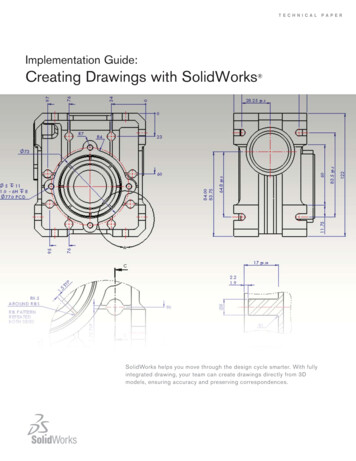
Chapter 4 – Dimensioning DrawingsIn this chapter, we are going to learn how to dimension the drawings we arecreating. AutoCAD supplies many different tools for creating these dimensionsquickly and easily. We will cover the basic tools.The dimensions created by AutoCAD come from the dimensions you usedwhen you drew the part. It is very important that you use the correct dimensionswhen you are drawing. Many students will use a scaling factor when they aredrawing to make it easier to keep the entire drawing on the screen. This is completelyunnecessary and undesirable. If the drawing or a line extends beyond the edge of thescreen use the zoom command to show the entire drawing.zoomall{This will display everything you have drawn onthe screen. If it is still too large, roll the mousewheel towards you to reduce the size farther.}We are going to start by drawing thefront, top, and right views of the object shownon the right. We will use a first angleprojection for our drawings.Start as you did before by creatingObj, Hide, Proj, Center, and Fold layers. Setthe appropriate line types for hidden andcenter lines and select colors as appropriate.You can start by drawing the frontview. It is a basic box with two holes in it.Make sure you use the correct dimensions.Use exactly the same techniques you used inthe last chapter to draw a simple box shownbelow with two holes as shown below. Thetwo lines extending up from the bottomcorners are just construction lines for thecreation of the holes and they can be erasedafter the holes have been created.Next we need to cut off the corners onthe front plate of the part. This can be donewith the FILLET command. Two thingsmust be defined for the FILLET commandbefore we can use it. We must set the radiusof the fillet and in this case, we want to turn trimming off so that the tangent lines areleft in place. Normally we would want AutoCAD to remove these lines.The FILLET command remembers the settings so we only have to makechanges to the radius and trim settings when we want it to work differently than thelast time we used the command. Initially the radius is set to zero and trimming isturned on. You will always need to set the radius the first time you use the command.3.016.0Dia 3.0R2.06.58.010.03.08.04.09.0filletCurrent settings: Mode TRIM, Radius 0.0000Select first object or[Undo/Polyline/Radius/Trim/Multiple]: R{enter R to change theradius}Specify fillet radius 0.0000 :2{enter 2 to set the radius}Dimensioning Drawings with AutoCAD – R GreenleePage 1
Select first object orUndo/Polyline/Radius/Trim/Multiple]:{enter T to change thetrim option}Enter Trim mode option [Trim/No trim] Trim : NoTSelect the top and left side of the boxto create the first rounded corner then repeatthe command and select the top and right sideof the box. You should be left with the objectshown on the right.Now we can draw the folding lines and start projecting the features shown onthe front view to the right and top views. Remember that we are creating a first angleprojection so the top view is below the front view and the right view is to the left.After the folding and projecting lines are drawn, change to the object layer anddraw the right edge of the object in the rightview. You can draw it with the mouse thentrim it using the projection lines like we did inthe previous assignments. When you havefinished, you should have a drawing similar tothe one shown on the right.The other vertical edges in the rightview can be created with the OFFSETcommand. This command will duplicate aline at a specified offset distance. EnterOffsetSpecify offset distance: 0.0 :Select object to offset:3Select object to offset:{select the right edge of theobject then click to the left ofthe line}{click on the new line youcreated then to the left of thatline to create another line offsetby 3}Repeat the above process by clicking on the line just created then to the left ofthe line to place the new offset until all of vertical lines have been created.Next, you can draw the bottom of the object by creating a line that connectsthe bottoms of the left most and right most lines. Use the OFFSET command tocreate the slot in the bottom of the object thenuse the TRIM command to trim the line to thecorrect length. The results are shown in thefigure on the right.Create this lineThe OFFSET and TRIM commandswith the offsetcommandare very useful and can frequently be used toeliminate typing coordinates when creatingUse the trim command tolines and other objects.remove these linesDimensioning Drawings with AutoCAD – R GreenleePage 2
Continue as we have before andcomplete the three views. These are shown onthe right. Remember that this is a first angleprojection. The right view is on the left, thetop view is on the bottom, and the front viewis between the other two.Moving ViewsIf the views you have drawn are too close together to accommodatedimensions, use the MOVE command to move them farther apart. Use the Windowoption of the MOVE command to select only those lines and arcs that are part of theview and move them farther down the drawing. Before you start, make sure thatORTHO is set to ON so that the view can only be moved vertically. The MOVEcommand is illustrated below.MoveSelect objects:{enter w to create a window around theobject}Specify first corner:{1 - click below and to the left of all linesin the top view}Specify opposite corner:{2 - click above and to the right of all ofthe lines in the top view}Select objects:{if all of the lines have been selected,press enter otherwise continue to selectlines}Specify base point or [Displacement] {3 - click on a point in the top viewyou wish to use as a handle to movethe view}Specify second point or{drag the view to where you want it andclick with the mouse to relocate it}W2 - Click3 – Base Point1 - ClickDimensioning Drawings with AutoCAD – R GreenleePage 3
The figure on the right shows the threeviews after the top view has been moved.You now have space to create the dimensions.Adding DimensionsAutoCAD supplies a several menu items for creating dimensions. Clicking onthe “Annotate” tab to produces the ribbon shown below.Annotate TabDimensionpull downAdjust SpaceContinue or baselineThere are two very useful commands. There are:Adjust SpaceContinueBaselinethis controls the spacing between nested dimensionsthis allows dimensions to continue so that the end of oneis the beginning of the nextthis allows multiple dimensions to start at the same baselocationIf you click on the “Dimension” pull down AutoCAD will produce the menushown on the right.LinearAlignedAngularArc LengthRadiusDiameterproduces normal horizontal and verticaldimensionsproduces dimensions that are aligned withpart featuresis used to create angular dimensionsdimensions the arc length of an arc or apolylinecreates a radius dimensioncreates a diameter dimensionDimensioning Drawings with AutoCAD – R GreenleePage 4
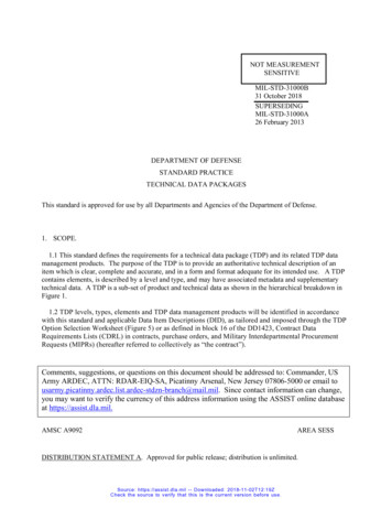
We can use these tools to create dimensions on the drawing we have created.Remember before you start creating dimensions there are several rules tofollow.1. The person who makes the part must measure it exactly the way youdimensioned it. If you dimension it in a way that is difficult to measure,you have made the part much more expensive to make without improvingthe quality or usefulness of the part.2. Dimension in the view where you see the shape. Holes should bedimensioned where you see the round shape.3. Do not dimension to hidden lines if possible. You can usually dimensionthe feature in a different view where it is not hidden.First, click on the “Linear” dimensionbutton then (1) click on the bottom, left cornerof the front view. This is the beginning pointfor the dimensions. We want to create adimension from this point to the center of theleft circle. Click on the center (2) of the leftmost circle in the front view then move themouse to a position below the front view and(3) click to locate the text.4.002 – Click3 – Clickh1 – ClickNow click on the “Continue” buttonand dimension to the center of the next circlethen to the lower right corner of the part in thefront view. Press the ESC key when you havefinished. Your drawing should look like theone on the right.Next we will dimension the holes andthe rounds in the corners. Click on thedimension pull down and click on the“Diameter” button. Use this command todimension both circles.4.008.004.00Ø3.00Ø3.00R2.00R2.00Next use the “Radius” button todimension the rounded corners. Click on thebutton, then click on the arc you want todimension, then move the mouse to the placeyou where you want the annotation to appearand click to place it. When you have finished,the drawing should look like the one at theright.Dimensioning Drawings with AutoCAD – R Greenlee4.008.004.00Page 5
Next we will add width dimensions to the right view. We will use the left faceof the right view as a base datum and dimension from there. Click on the “Linear”dimension button and create a dimension from the left face to the left side of the slot.Next click on the arrow at the right side of the “Continuous” button and click on 06.008.004.009.00“Baseline” button. Use the same technique to dimension the height of the slot and theheight of the part. Add dimensions to the view until it looks like the figure below.Dimension SizeSometimes, the dimensions are either too large or too small. You can usuallyfix the problem with the DIMSCALE command. The DIMSCALE command lets youchange the scale of the dimensioning size by specifying a scaling factor. A factorgreater than one makes the dimensions larger and a factor smaller than one makesthem smaller. Changing the scaling factor affects the size of the text, arrowheads, andgap between the extension lines and the point selected for the dimension.The DIMSCALE command is illustrated below. Here we are changing thedimensioning scale from 1 the default value to 4 which will make the dimensions 4times as large.dimscaleEnter new value for DIMSCALE 1.0000 : 4The DIMSCALE command will not change dimensions that have been drawn.It only affects new dimensions. You must erase the old dimensions and recreate themwith the new dimensioning scale factor. You may have to try several differentdimensioning scales before getting the correct size for the dimensions.More Dimensioning ProblemsDimensioning Drawings with AutoCAD – R GreenleePage 6
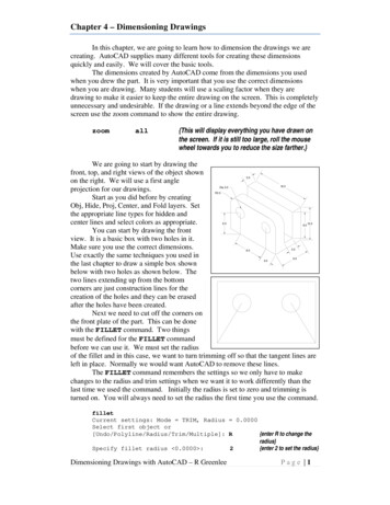
Click here tocreate thedialog boxClick toModify thesettingsThe DIMSCALE command will change the size of the dimensions but theremay be other problems. A frequent problem is the number of decimals shown in thedimension. The AutoCAD default is 4 decimal places and frequently this is too many.To change the number of decimal places and many other dimensioning problems, youmust open and make changes in the dimension style manager.You open the dimension style manager by clicking on the small arrow to theright of the dimension tab. This produces the dimension style dialog box. In this boxclick on the “Modify” button then in subsequent dialog boxes, make appropriatechanges to the dimensioning.We will not cover the dimension styles in detail here but we can point outsome of the more commonly used style components that can be changed. When youclick on the “Modify” button, the style manager opens. It is a dialog box with severaltabs at the top. Clicking on a tab changes the dialog box allowing you to changedifferent features of the dimension.If you click on the “Symbols and Arrows” tab, the following dialog box willbe created. You can use this dialog box to change the size of arrowheads and the sizeof the center marks for circles and arcs.Change arrowhead sizeChange center mark sizeDimensioning Drawings with AutoCAD – R GreenleePage 7
You can change the text height used for dimension text with the dialog boxunder the “Text” tab.Text sizeThe number of decimals shown in the dimension can be changed with the“Primary Units” tab.Number of DecimalsSuppress trailing zerosWhen you have made the changes you want to make, click on the “OK” buttonat the bottom of the dialog box. The “Style Manager” dialog box will appear. Clickon the “Set Current” button then on the “Close” button. This will make the changesyou have made the current settings for AutoCAD.You must erase and redraw the dimension to see the changes you have made.Like many items in AutoCAD, the changes are not dynamic.Dimensioning Drawings with AutoCAD – R GreenleePage 8
Dimensioning Drawings with AutoCAD – R Greenlee Page 4 The figure on the right shows the three views after the top view has been moved. You now have space to create the dimensions. Adding Dimensions AutoCAD supplies a several menu items for creating dimensions. Clicking