Transcription
SCU-1600UniversalTransmitterUser Manual
UNIVERSAL TRANSMITTERSCU-1600CONTENTSWarning. 2Symbol identification. 3Safety instructions. 3How To Detach SCU-1600. 5When front LED lights red / display shows AO.ER. 5Advanced features. 6Application. 6Technical characteristics. 6SCU-PDM1 Display / programming front. 7Mounting / demounting the SCU-PDM1. 8Applications. 9Part Numbers. 10Electrical specifications. 10Visualization in the SCU-PDM1 of sensor error detection andinput signal outside range. 14Sensor error detection limits. 14Error indications. 15Connections. 16Block diagram. 17Configuration / operating the function keys. 18Routing diagram. 25Routing diagramAdvanced settings (ADV.SET).Routing diagramManual deactivation of the latch function.Scrolling help text in display line 3.Graphic depiction of latch function setpoint.Graphic depiction of latch function window.Graphic depiction of relay action setpoint.Graphic depiction of relay action window.SCU-1600282930323334341
WARNINGGENERALThis device is designed for connection to hazardous electricvoltages.Ignoring this warning can result in severe personal injury ormechanical damage.To avoid the risk of electric shock and fire, the safety instructionsof this manual must be observed and the guidelines fol lowed.The specifications must not be exceeded, and the device mustonly be applied as described in the following.Prior to the commissioning of the device, this manual must beexamined carefully.Only qualified personnel (technicians) should install this device.If the equipment is used in a manner not specified by themanufacturer, the protection provided by the equipment may beimpaired.WARNINGUntil the device is fixed, do not connect hazardous voltages tothe device.The following operations should only be carried out on aHAZARD OUSdisconnected device and under ESD safe conditions:VOLTAGEGeneral mounting, connection and disconnection of wires.Troubleshooting the device.WARNINGINSTALLATIONTo keep the safety distances, the relay contacts on the devicemust not be connected to both hazardous and non-hazard ousvolt ages at the same time.SCU-1600 must be mounted on a DIN rail according to DIN46277.WARNINGDo not open the front plate of the device as this will causedamage to the connector for the display / programming frontSCU-PDM1. This device contains no DIP-switches or jumpers.2SCU-1600
SYMBOL IDENTIFICATIONTriangle with an exclamation mark: Warning / demand.Potentially lethal situations.The CE mark proves the compliance of the device withthe essential requirements of the directives.The double insulation symbol shows that the deviceis protected by double or reinforced insulation.SAFETY INSTRUCTIONSDEFINITIONSHazardous voltages have been defined as the ranges: 75 to 1500 Volt DC, and50 to 1000 Volt AC.Technicians are qualified persons educated or trained to mount, operate, and alsotroubleshoot technically correct and in accordance with safety regulations.Operators, being familiar with the contents of this manual, adjust and operatethe knobs or potentiometers during normal operation.RECEIPT AND UNPACKINGUnpack the device without damaging it. The packing should always follow thedevice until this has been permanently mounted.Check at the receipt of the device whether the type corresponds to the oneordered.ENVIRONMENTAvoid direct sunlight, dust, high temperatures, mechanical vibrations and shock,as well as rain and heavy moisture. If necessary, heating in excess of the statedlimits for ambient temperatures should be avoided by way of ventilation.All devices fall under Installation Category II, Pollution Degree 1, and InsulationClass II.MOUNTINGOnly technicians who are familiar with the technical terms, warnings, and instruc tions in the manual and who are able to follow these should connect the device.Should there be any doubt as to the correct handling of the device, pleasecontact:www.automationdirect.comSCU-16003
Mounting and connection of the device should comply with national legislation formounting of electric materials, i.e. wire cross section, protective fuse, and location.Descriptions of input / output and supply connections are shown in the blockdiagram and side label.The following apply to fixed hazardous voltages-connected devices:The max. size of the protective fuse is 10 A and, together with a powerswitch, it should be easily accessible and close to the device. The powerswitch should be marked with a label indicating that it will switch off thevolt age to the device.Year of manufacture can be taken from the first two digits in the serial number.UL INSTALLATION REQUIREMENTSUse 60/75 C copper conducters onlyFor use only in pollution degree 2 or betterMax. ambient temperature. 60 CMax. wire size. AWG 26-14UL file number. E191072CALIBRATION AND ADJUSTMENTDuring calibration and adjustment, the measuring and connection of externalvoltages must be carried out according to the specifications of this manual. Thetechnician must use tools and instruments that are safe to use.NORMAL OPERATIONOperators are only allowed to adjust and operate devices that are safely fixed inpanels, etc., thus avoiding the danger of personal injury and damage. This meansthere is no electrical shock hazard, and the device is easily accessible.CLEANINGWhen disconnected, the device may be cleaned with a cloth moistened withdistilled water.4SCU-1600
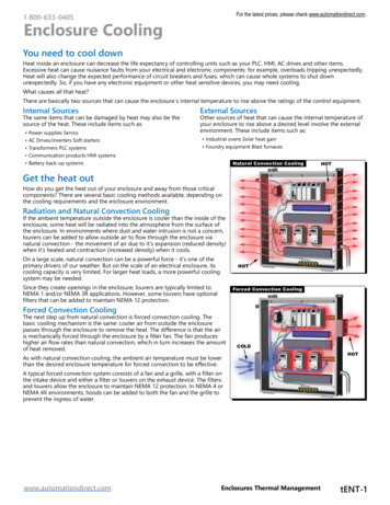
HOW TO DETACH SCU-1600First, remember to detach the connectors with hazardous voltages.Picture 1:Detach the device from the DIN railby lifting the bottom lock.When front LED lights red / display shows AO.ERSCU-1600 is designed as a SIL 2 device with a high safety level. Therefore, acontinuous measurement of the outgoing current is carried out on a 4.20 mAand 20.4 mA output signal. If the current output signal is different from theinternal calculated output value or the current output is 0 (due to e.g. an opencircuit breakage), an error mode switches on the red front LED and disables therelays. This function is not a default option but must be actively selected viathe programming menu (S4-20 & S20-4).The error mode can only be reset by switching off and then switching on thesupply voltage to the device.SCU-16005
UNIVERSAL TRANSMITTERSCU-1600 Input for RTD, TC, Ohm, potentiometer, mA and V 2-wire supply 16 V FM-approved for installation in Div. 2 Output for current, voltage and 2 relays Universal AC or DC supplyAdvanced features Programmable via detachable display front (SCU-PDM1), process calibration,signal and relay simulation, password protection, error diagnostics and selectionof help text in several languages.Application Linearised, electronic temperature measurement with RTD or TC sensor. Conversion of linear resistance variation to a standard analogue current /voltage signal, i.e. from solenoids and butterfly valves or linear movementswith attached potentio meter. Power supply and signal isolator for 2-wire transmitters. Process control with 2 pairs of potential-free relay contacts and analogueoutput. Galvanic separation of analogue signals and measurement of floating signals. The SCU-1600 is designed according to strict safety requirements and is thussuit able for application in SIL 2 installations.Technical characteristics When SCU-1600 is used in combination with the SCU-PDM1 display /programming front, all operational parameters can be modified to suit anyapplication. As the SCU-1600 is designed with electronic hardware switches, itis not necessary to open the device for setting of DIP switches. A green / red front LED indicates normal operation and malfunction. A yellowLED is ON for each active output relay. Continuous check of vital stored data for safety reasons. 4-port 2.3 kVAC galvanic isolation.6SCU-1600
SCU-PDM1 DISPLAY / PROGRAMMING FRONTFunctionalityThe simple and easily understandable menu structureand the explanatory help texts guide you effortless ly andautomatically through the configuration steps, thus makingthe product very easy to use. Functions and configurationoptions are described in the section ”Configuration /operating the function keys”.Application Communications interface for modification of operational parameters in SCU1600. Can be moved from one SCU-1600 device to another and download theconfiguration of the first transmitter to subsequent transmitters. Fixed display for readout of process data and status.Technical characteristics LCD display with 4 lines; Line 1 (H 5.57 mm) shows input signal, line 2(H 3.33 mm) shows units, line 3 (H 3.33 mm) shows analog output or tag no.and line 4 shows communication and relay status. Programming access can be blocked by assigning a password. The password issaved in the transmitter in order to ensure a high degree of protection againstunauthorised modifications to the configuration.Mounting / installation Click SCU-PDM1 onto the front of SCU-1600.SCU-16007
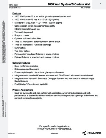
MOUNTING / DEMOUNTING THE SCU-PDM11: Insert the taps of SCU-PDM1 into the holes at the top of the device.2: Swing SCU-PDM1 into place.Demounting of SCU-PDM13: Push the release button on the bottom of SCU-PDM1 and swing SCU-PDM1 up.Note: C an be installed or removed whether the signal conditioner is powered ornot.31 OK34501 248SCU-1600
APPLICATIONSInput signals:CurrentVolt - Potentio meterRTD and lin.RageTC44 43*--42 41* Order separately: SCU-CJC1 Optional External CJCconnector. See the connection drawing on page 16.Output signals:Relays121413 - 10 V10 V-1V1V11 --24232221Analogue, 0/4.20 mA and voltageSupply:3321.6.253 VACor19.2.300 VDC3231SCU-16009
Part NumbersSCU-1600 Universal transmitterSCU-PDM1 Display / programming frontSCU-CJC1 Optional External CJC connectorElectrical specificationsEnvironmental conditionsSpecifications range.Calibration temperature.Relative humidity.Protection degree.Mechanical specificationsDimensions (HxWxD).-20 C.60 C (-4 F.140 F)20.28 C (68 F.82.4 F) 95% RH (non-cond.)IP20 109 x 23.5 x 104 mm(4.3 x 0.9 x 4.1 in)Dimensions, with SCU-PDM1 (HxWxD). 109 x 23.5 x 116 / 131 mm(4.3 x 0.9 x 4.6 / 5.2 in)Weight. 170 gWeight with SCU-PDM1. 185 g / 270 gMax. wire size. 1 x 2.5 mm2 (14 AWG) stranded wireScrew terminal torque. 0.5 Nm (0.37 ft lb)Vibration. IEC 60068-2-6 : 20072.13.2 Hz. 1 mm13.2.100 Hz. 0.7 gCommon specificationsSupply voltage, universal. 21.6.253 VAC, 50.60 Hzor 19.2.300 VDCMax. consumption. 2.5 WFuse. 400 mA SB / 250 VACIsolation voltage, test / operation. 2.3 kVAC / 250 VACCommunications interface. Programming front SCU-PDM1Signal / noise ratio. Min. 60 dB (0.100 kHz)Response time (0.90%, 100.10%):Temperature input. 1 smA / V input. 400 msAccuracy, the greater of the general and basic values:InputtypeAll10General valuesAbsoluteTemperatureaccuracycoefficient 0.1% of span 0.01% of span / CSCU-1600
Basic valuesBasicaccuracy 4 µA 20 µV 0.2 C 0.1 Ω 0.1 ΩInputtypemAVoltPt100Linear resistancePotentiometerTC type:E, J, K, L, N, T, UTC type: R, S, W3,W5, LRTC type: B85.200 CTC type: B200.1820 CTemperaturecoefficient 0.4 µA / C 2 µV / C 0.01 C / C 0.01 Ω / C 0.01 Ω / C 1 C 0.05 C / C 2 C 0.2 C / C 4 C 0.4 C / C 2 C 0.2 C / CEMC immunity influence. 0.5% of spanExtended EMC immunity:NAMUR NE 21, A criterion, burst. 1% of spanAuxiliary supplies:2-wire supply (terminal 44.43). 25.16 VDC / 0.20 mARTD, linear resistance and potentiometer inputInput for RTD types:Pt10, Pt20, Pt50, Pt100, Pt200, PT250, Pt300, Pt400, Pt500, Pt1000Ni50, Ni100, Ni120, Ni1000, Cu10, Cu20, Cu50, 0Ni50.Ni1000Cu10.Cu100Lin. RPotentiometer-200 C-60 C-200 C0Ω10 Ω 850 C 250 C 260 C10000 Ω100 kΩIEC 60751DIN 43760α 0.00427-Cable resistance per wire (max.), RTD.Sensor current, RTD.Effect of sensor cable resistance(3- / 4-wire), RTD.Sensor error detection, RTD.Short circuit detection, RTD.50 ΩNom. 0.2 mA 0.002 Ω / ΩYes 15 ΩSCU-160011
TC R0 C-100 C-100 C-180 C-200 C-180 C-50 C-50 C-200 C-200 C0 C0 C-200 C 1820 C 1000 C 1200 C 1372 C 900 C 1300 C 1760 C 1760 C 400 C 600 C 2300 C 2300 C 800 CIEC 60584-1IEC 60584-1IEC 60584-1IEC 60584-1DIN 43710IEC 60584-1IEC 60584-1IEC 60584-1IEC 60584-1DIN 43710ASTM E988-90ASTM E988-90GOST 3044-84Cold junction compensation (CJC):via external sensor in connector SCU-CJC120.28 C 1 C-20.20 C / 28.70 C 2 Cvia internal CJC sensor. (2.0 C 0.4 C * Δt)Δt internal temperature - ambient temperatureSensor error detection, all TC types. YesSensor error current:when detecting. Nom. 2 μAelse. 0 μACurrent inputMeasurement range. 0.20 mAProgrammable measurement ranges. 0.20 and 4.20 mAInput resistance. Nom. 20 Ω PTC 50 ΩSensor error detection:Loop break 4.20 mA. YesVoltage inputMeasurement range. 0.12 VDCProgrammable measurement ranges. 0.1 / 0.2.1 / 0.5 / 1.5 /0.10 and 2.10 VDCInput resistance. Nom. 10 MΩ12SCU-1600
Current outputSignal range (span).Programmable signal ranges.Load (max.).Load stability.Sensor error detection.NAMUR NE 43 Upscale / Downscale.Output limitation:on 4.20 and 20.4 mA signals.on 0.20 and 20.0 mA signals.Current limit.Voltage outputSignal range.Programmable signal ranges.0.20 mA0.20 / 4.20 / 20.0 and 20.4 mA20 mA / 800 Ω / 16 VDC 0.01% of span / 100 Ω0 / 3.5 / 23 mA / none23 mA / 3.5 mA3.8.20.5 mA0.20.5 mA 28 mA0.10 VDC0.1 / 0.2.1 / 0.10 / 0.5 /1.5 / 2.10 / 1.0 / 1.0.2 / 5.0 /5.1 / 10.0 og 10.2 VLoad (min.). 500 kΩRelay outputsRelay functions. Setpoint, Window, Sensor error,Latch, Power and OffHysteresis. 0.100%On and Off delay. 0.3600 sSensor error detection. Break / Make / HoldMax. voltage. 250 VRMSMax. current. 2 A / AC or 1 A / DCMax. AC power. 500 VAI.S. approvalFM, applicable in. Class I, Div. 2, Group A, B, C, DClass I, Div. 2, Group IICZone 2Max. ambient temperature for T5. 60 CObserved authority requirementsEMC 2004/108/EC.LVD 2006/95/EC.FM.UL, Standard for Safety.StandardEN 61326-1EN 61010-13600, 3611, 3810 and ISA 61010-1UL 508of span of the currently selected measurement rangeSCU-160013
Visualization in the SCU-PDM1 of sensor error detection andinput signal outside rangeSensor error igurationR1, ERR.ACT NONE - R2, ERR.ACT NONE,OUT.ERR NONE.Else:Sensor error detection:OFFONOutside range readout (IN.LO, IN.HI):If the valid range of the A/D converter or the polynomial is exceededRangeReadoutLimitIN.LO -25 mV0.1 V / 0.2.1 VIN.HI 1.2 VIN.LO -25 mV0.10 V / 2.10 VIN.HI 12 VIN.LO -1.05 mA0.20 mA / 4.20 mAIN.HI 25.05 mAIN.LO 0Ω0.800 ΩIN.HI 1075 ΩIN.LO 0Ω0.10 kΩIN.HI 110 kΩIN.LO -0.5 %IN.HI 100.5 %IN.LO temperature range -2 CTC / RTDIN.HI temperature range 2 CDisplay readout below min.- / above max. (-1999, 9999):InputRangeAllAllReadout-19999999LimitDisplay readout -1999Display readout 9999Sensor error detection limitsSensor error detection (SE.BR, SE.SH):InputCURRPOTMLIN.RTEMP14RangeLoop break (4.20 mA)All, SE.BR on all 3-wire0.800 Ω0.10 kΩTCRTD, 2-, 3-, and 4-wireNo SE.SH for Cuxx, Pt10, Pt20 and E.SHLimit 3.6 mA; 21 mA ca. 126 kΩ ca. 875 Ω ca. 11 kΩ ca. 750 kΩ / (1.25 V) ca. 15 kΩ ca. 15 Ω
Error indicationsReadout at hardware errorError searchReadoutTest of internal CJC sensorCJ.ERChecksum test of the configuration in FLASHFL.ERCheck measurement of analog output currentAO.ERCommunications test SCU-PDM1 / SCU-1600Internal communication errorCheck that input signal matches input configurationCheck that saved configuration in SCU-PDM1 matchesdeviceNO.CONO.OUIN.ERTY.ERError causeCJC sensor defect or temperature outside rangeError in FLASH1) No load on the current output (only S4.20/S20.4 mA)Connection errorOutput controller error1) Error levels on inputConfiguration is not SCU1600! Error indications in the display flash once per second. The help text explains the error.1) The error is reset by switching off and then switching on the supply voltage to the device.SCU-160015
CONNECTIONSSupply:313233Inputs:RTD, 2-wireRTD, 3- / 4-wireTC, internalCJC sensorResistance, 2-wire41 42 43 4441 42 43 4441 42 43 4441 42 43 44 Resistance,3- / 4-wire41 42 43 44-Potentiometer2-wire transmitterCurrent41 42 43 4441 42 43 4441 42 43 44-- - *TC, CJC connector41 42 CJC 41 42 43 44 44* Order separately:Optional External CJC connectorSCU-CJC1-VoltageTxOutputs:CurrentVoltage, 1 VVoltage, 10 VRelays11 12 13 1411 12 13 1411 12 13 1421 22 23 24-16mA -V -SCU-1600V R1R2
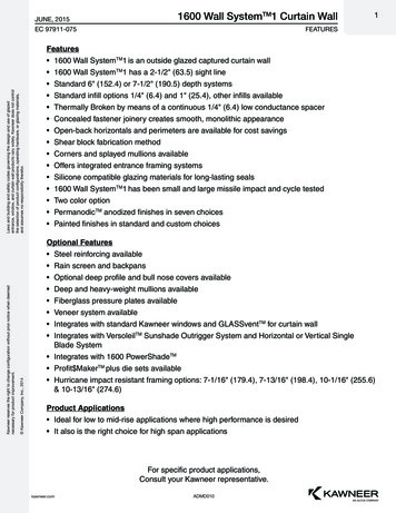
1232RTD and lin.R,450.0Potentiome terl / minVALVE 5TC* 0.2 mAMUXVloopA/DGreenCPUEEPROMD/A500 WYellowYellowRed50 W*Order separately: Optional External CJC connector SCU-CJC1444342CJC41PTC20 WSCU-1600Safety333112Supply21.6.253 VAC or19.2.300 VDCSupplyI 10 VmA14VmAV1VI-IVOut. Out.Relay 1Relay 1Relay 2Relay 2I VOut.13112423222117SCU-1600 Current-2-wire transmitter- BLOCK DIAGRAMVoltage
CONFIGURATION /OPERATING THE FUNCTION KEYSDocumentation for routing diagram.In generalWhen configuring the SCU-1600, you will be guided through all parameters andyou can choose the settings which fit the application. For each menu there is ascrolling help text which is automatically shown in line 3 on the display.Configuration is carried out by use of the 3 function keys:123will increase the numerical value or choose the next parameterwill decrease the numerical value or choose the previous parameterwill accept the chosen value and proceed to the next menuWhen configuration is completed, the display will return to the default state 1.0.Pressing and holding 3 will return to the previous menu or return to the defaultstate (1.0) without saving the changed values or parameters.If no key is activated for 1 minute, the display will return to the default state(1.0) without saving the changed values or parameters.Further explanationsFast setpoint adjustment and relay test: These menus allow you to make aquick setpoint change and relay test when the FastSet menu is activated. Thisfunction can only be activated when the relays are set for setpoint functionand are controlled by a setpoint.Pressing 1 and 2 simultaneously will activate a relay test and change the stateof the relay.Pressing 3 will save the setpoint change.Holding down 3 for more than 1 second will return the unit to the default statewithout saving the setpoint change.Password protection: Programming access can be blocked by assigning apassword. The password is saved in the transmitter in order to ensure a highdegree of protection against unauthorized modifications to the configuration.Default password 2008 allows access to all configuration menus.18SCU-1600
Signal and sensor error info via display front SCU-PDM1Sensor error (see limits in the table) is displayed as SE.BR (sensor break) or SE.SH(sensor short). Signals outside the selected range (not sensor error, see tablefor limits) are displayed as IN.LO indicating low input signal or IN.HI indicatinghigh input signal. The error indication is displayed in line 3 as text and at thesame time the backlight flashes. Line 4 of the display is a status line whichdisplays status of relay 1 and relay 2, COM (flashing bullet) indicating correctfunctioning of SCU-PDM1 and arrow up/down which indicates tendencyreadout of the input signal. If the figure 1 or figure 2 flashes, the unit hasdetected that the setpoint has been exceeded and that the relay is in “delay”mode. When the delay time has passed and the relay makes/breakes, the relaysign either displays or disappears.Signal and sensor error indication without display frontStatus of the unit can also be read from the red/green LED in the front of the device.Green flashing LED 13 Hz indicates normal operation.Green flashing LED 1 Hz indicates sensor error.Steady red LED indicates internal error.Relay functions6 different settings of relay function can be selected.Setpoint:The unit works as a single limit switchWindow:The relay has a window that is defined by a low and a highsetpoint. On both sides of the window the relay has thesame status.Error function: The relay is activated by sensor error.Power:The relay is activated as long as the power is on.Off:The relay is deactivated.Latch:The relay is latched. Only valid for setpoint and windowfunction.Increasing/decreasing: The relays can be set to activate at increasing ordecreasing input signal.Delay: An ON and an OFF delay can be set on both relays in the range0.3600 s.Hysteresis: 0.0.100.0%.SCU-160019
LatchWhen the setpoint is exceeded the relay outputs enters an alarm state. The latchfunction of the SCU-1600 will hold the relays in this state until the functionis deactivated manually. The latch function can be applied when the relayfunction setpoint or window is selected.The latch function can be selected separately for each relay output. If theconfiguration is copied from one device to another by way of the SCU-PDM1,the latch function must be reconfigured.The latch function activates and holds the relays when the input signal risesabove or falls below the selected setpoints and the relay action has beenselected as increasing or decreasing.The window function is selected by choosing ”window” in the menu and defininga high and a low setpoint.It can be selected for each relay contact whether the contact is open or closedinside the window. This selection is made in the menu R1.cont and R2.cont.The setpoint function is selected by choosing ”setpoint” in the menu and enteringthe desired limit. The device then works as a single limit switch.An activated relay means that the contact is closed if the contact function”normally open” is selected, and the contact is open if the contact function”normally closed” is selected.The delay time for activation and deactivation can be set independently of eachother in the menus ON.DEL and OFF DEL respectively.If the relay function ”Error” is active, the relay will latch when a sensor erroroccurs and will not be deactivated automatically when the sensor error isrectified.The relay can only be deactivated by an operator and only when the normalconditions for deactivation are met. If the input signal still has a value that willactivate the relay, the relay will latch again.See the graphic depiction of the setpoint and window functions on pages 32 and33.20SCU-1600
Manual deactivation of the latch functionIf the relay outputs are activated and thereby latched, it will be indicated inthe display. The backlight flashes and the scrolling help text tells you how todeactivate the output. Manual deactivation is carried out by way of the frontbuttons on the SCU-PDM1. Use 1 and 2 to navigate in the menu and 3 tovalidate your selection. If the password protection has been activated, thepassword must be entered in order to access the deactivation menu. See themenu structure on page 29.Advanced functionsThe device gives access to a number of advanced functions which can be reachedby answering “Yes” to the point “adv.set”.Display setup: Here you can adjust the brightness contrast and the backlight.Setup of TAG numbers with 6 alphanumerics. Selection of functional readout inline 3 of the display - choose between readout of analogue output or tag no.Two-point process calibration: The device can be process-calibrated in 2points to fit a given input signal . A low input signal (not necessarily 0%) isapplied and the actual value is entered via SCU-PDM1. Then a high signal (notnecessarily 100%) is applied and the actual value is entered via SCU-PDM1. Ifyou accept to use the calibration, the device will work according to this newadjustment. If you later reject this menu point or choose another type of inputsignal the device will return to factory calibration.Process simulation function: If you agree to the point “EN.SIM” it is possibleto simulate an input signal by means of the arrow keys and thus control theoutput signal up or down. When you finalize the point with 3, the devicereturns to normal mode. The following point allows you to activate relay 1and relay 2 by means of the arrow-keys up/down. You must exit the menu bypressing 3 (no time-out).Password: Here you can choose a password between 0000 and 9999 in orderto protect the device against unauthorized modifications to the configuration.The device is delivered default without password. If you have locked the devicewith a password by mistake, you can always open the menu by using themaster password 2008.Language: In the menu ”lang.setup” you can choose between 7 differentlanguage versions of help texts that will appear in the menu. You can choosebetween UK, DE, FR, IT, ES, SE and DK.SCU-160021
Auto diagnosisThe device performs an advanced auto diagnosis of the internal circuits.The following possible errors can by displayed in the front unit SCU-PDM1.CJ.ER - CJC sensor defect or CJC temperature outside rangeFL.ER - Flash errorAO.ER - No load on the current output (only for S4.20 mA / S20.4 mA)NO.CO - Connection errorIN.ER - Error levels on inputTY.ER - C
8 SCU-1600 MOUNTING / DEMOUNTING THE SCU-PDM1 1:Insert the taps of SCU-PDM1 into the holes at the top of the device. 2:Swing SCU-PDM1 into place. Demounting of SCU-PDM1 3:Push the release button on the bottom of SCU-PDM1 and swing SCU-PDM1 up. Note: Can be installed or removed whether the signal conditioner is powered or not.