Transcription
T E C H N I C A LImplementation Guide:Creating Drawings with SolidWorks SolidWorks helps you move through the design cycle smarter. With fullyintegrated drawing, your team can create drawings directly from 3Dmodels, ensuring accuracy and preserving correspondences.P A P E R
You can generate drawings in SolidWorks the same way you would generate them in 2D drafting and drawing systems.However, creating 3D models and generating drawings from the model have many advantages; for example: Designing models is faster than drawing lines. SolidWorks creates drawings from models, so the process is efficient. You can review models in 3D and check for correct geometry and design issues before generating drawings,so the drawings are more likely to be free of design errors. You can insert dimensions and annotations from model sketches and features into drawings automatically, soyou do not have to create them manually in drawings. Parameters and relations of models are retained in drawings, so drawings reflect the design intent of the model. Changes in models or in drawings are reflected in their related documents, so making changes is easier anddrawings are more accurate.Creating DrawingsDrafting in SolidWorksTo draft a drawing in SolidWorks without creating a model:1. Open a Newdrawing document. Choose a template.2. Draw lines, rectangles, circles, and other entities with the tools on the Sketch toolbar.3. Dimension the entities with the Smart Dimensiontool on the Dimensions/Relations toolbar.4. Add annotations (Notes, Geometric Tolerance Symbols, Balloons, and so on) with tools on theAnnotation toolbar.NOTE: See the next section for an alternative approach. See Drafting for further details on sketching in drawings.1
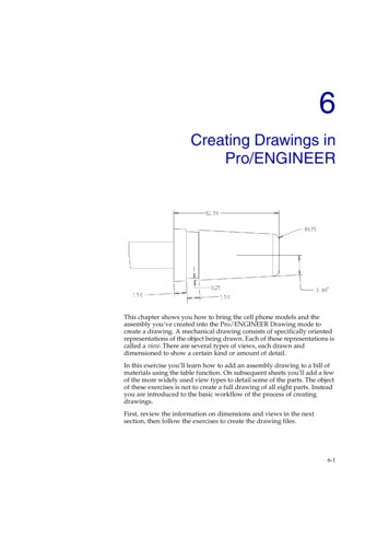
Creating Drawings from ModelsTo generate drawings from part and assembly documents:1. In a part or assembly document, click Make Drawing from Part/Assemblyselect a template in the Sheet Format/Size dialog box.on the Standard toolbar andThe View Palette opens on the right side of the window.2. Clickto pin the View Palette.3. Drag a view from the View Palette onto the drawing sheet.4. In the Drawing View PropertyManager, set options such as orientation, display style, scale, etc. then click.5. Repeat steps 3 and 4 to add views.Note: You can have any drawing views of any models in a given drawing document.MODEL PART DRAWING WITH SEVERAL VIEWS AND DIMENSIONS INSERTED2
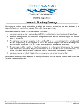
DraftingYou can draft in 2D in SolidWorks drawing documents using Sketch tools, Dimension tools, and Annotations as describedin Creating Drawings. Concepts to consider include:Sketch entitiesIn SolidWorks drawing documents, you can add sketch entities (lines, circles, rectangles, and so on)at any time. You can create your own line styles using layers, the Line Format tools, or Line StyleOptions.Drawing viewsYou can add sketch entities and annotations to the drawing sheet or to drawing views. Drawing viewsallow you to move and scale all the items in the view in one operation. You can insertempty views onto drawing sheets to contain drafted entities.StandardsThe drafted elements follow the standard specified in Tools, Options, Document Properties,Drafting Standard. Such items as dimension arrows, tolerances, annotation display, and so on aregenerated based on the standard, but you can also edit the items manually (choose a differentarrowhead style, for example).Sheet formatsSolidWorks drawing templates contain drawing sheet formats. You can edit the formats and savethem. You can also use a template without the format and create your own format, or import a blockfrom your 2D CAD system (a title block, for example).GridTo display a grid, right-click and select Display Grid. Specify the grid spacing and snap control inTools, Options, Document Properties, Grid/Snap.DimensionsDimensions in SolidWorks control the geometry. The sketch entity or model element must agree withits dimension. You cannot sketch an entity at a certain size and display a dimension of adifferent size. However, you can scale entities in a drawing sheet or drawing view.RelationsRelations (such as Horizontal, Concentric, Tangent) also control geometry. Some relations areinferenced as you sketch. You can add, display, and delete relations. To prevent automaticrelations, press Ctrl as you sketch, or clear Automatic relations in Tools, Options, System Options,Sketch, Relations/Snaps.AnnotationsMost annotations work with sketch entities the same as they do with drawings derived from3D models. Some exceptions are hole callout and autoballoon. Single balloons and stackedballoons appear with question marks, which you can replace with custom text. You can importinto drawings the dimensions and tolerances you create with DimXpert for parts.StandardsYou can set up styles in SolidWorks to format dimensions, but it is not necessary to do so for dimensions and otherannotations to follow a drawing standard.In SolidWorks, you set the standard for the current document in Tools, Options, Document Properties, DraftingStandard. The standard can be ANSI, ISO, DIN, JIS, BSI, GOST, or GB.3
You can also set the standard in a drawing document template.ANSIISODINJISBSIGOSTGB4
ScalingIn SolidWorks, drawing views can be at any scale (2:1, 1:2, for example) in relation to the model.Drawing SheetsYou can set separate scales for each drawing sheet in the Sheet Properties dialog box. Right-click thedrawing sheet outside any drawing views and select Properties. The scale of a drawing sheet appears inthe status line at the bottom of the SolidWorks window.Drawing ViewsThe scale of a drawing view is set in the PropertyManager when you select the view in the graphics area.A drawing view uses the scale of the drawing sheet unless: You specify another scale, either when creating the view or any time afterwards.- or The software needs to fit the view on the sheet with a certain scale.When you create a child view (Section View, Detail View, and so on), the scale of the child view can be the same as theparent view, the same as the drawing sheet, or a custom scale. This section view has the same scale as its parent view.5
Multiple DrawingsIn SolidWorks, you can have multiple drawing sheets in a drawing document, which is like having a set of drawings allin the same file. The sheets can contain drawing views of any parts or assemblies. You can switch between sheets byselecting a named tab at the bottom of the SolidWorks window. You can also add and delete sheets using the shortcutmenu.Title BlocksWhen you start a new drawing in SolidWorks, you select a template with a specified paper size and drawing sheetformat. The format can be standard, customized, or no format (specifying size only). When you define a title block, youcan specify which template fields are editable and hotspot areas you can click to enter title block data.Standard formats contain title blocks. SolidWorks allows you to edit the sheet format. (You can also save sheetformats for use in future drawings.) You can add, move, format, and delete lines and text.You can link note data to document properties such as file name, date, sheet number, and so on, or to customproperties that you define.The title block in a default landscape sheet format contains the following lines and text:In this example of editing the sheet format, a note with the company name is added, the note with the drawing name isedited, the lines are thickened, and a graphic is added.6
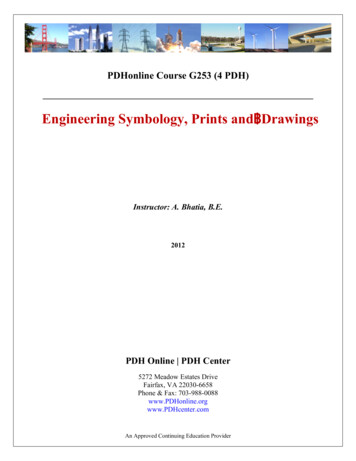
Drawing ViewsDrawing views are containers. Generally the contents are views of models. When you sketch in a drawing, or insertannotations or blocks, the entities belong to the active drawing view or drawing sheet. In SolidWorks you createdrawing views as follows: Standard views, such as standard 3 views, various named model views (such as isometric), and relativeviews created automatically from the model. Derived views (projected, auxiliary, section, detail, broken, broken-out section, alternate position views)created in one or two steps from another view (such as drawing a profile for a detail view). Empty views (for sketch entities, notes, and so on) inserted with the menu item Insert, Drawing View,Empty.Any changes in the model are automatically reflected in the drawing views.Aligning ViewsAlignment between views in SolidWorks is automatic and adjustable. For example, standard 3 views are automatically aligned vertically and horizontally, while section, projected, and auxiliary views are aligned in the appropriatedirection.You can drag the views within the correct alignment. You can also break the alignment and drag views anywhereon the drawing sheet. You can rotate views and hide or show views.STANDARD 3 VIEWS ARE ALIGNED AUTOMATICALLY. THE TOP VIEW IS CONSTRAINED HORIZONTALLY AND THERIGHT VIEW IS CONSTRAINED VERTICALLY BY DEFAULT.7
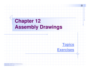
SECTION VIEWS ARE ALIGNED AUTOMATICALLY IN THE DIRECTION OF THE CUT. DETAIL VIEWS ARE NOT ALIGNED.Dimensions in DrawingsUsually you specify dimensions when you design a part, then insert the dimensions from the model into thedrawing. Changing a dimension in one document changes it in any associated documents.NOTE: You can set an option during installation of SolidWorks that prevents changes in dimensions in drawings fromaffecting part or assembly models.In SolidWorks, dimension formatting follows the standard that is set for the document in Tools, Options, DocumentProperties, Drafting Standard by default. You can change the document or template defaults for each type ofdimension listed under Tools, Options, Document Properties, Dimensions. SolidWorks uses styles to saveparticular formatting.Reference dimensions cannot be modified and do not change model geometry. However, when a model changes,reference dimensions update automatically. Model dimensions are linked to the model parametrically, using dimension names, and, when changed (in drawings or in model documents), modify the model.When you insert dimensions in part and assembly documents, they are marked for drawings unless you specifyotherwise. When you insert model dimensions with Model Items, automatically for a new drawing view, or withAutodimension, only the dimensions marked for drawings are inserted. When you insert an annotation view into adrawing, all annotations in the part or assembly are inserted in the drawing.8
DIMENSIONS DEFINE THE GEOMETRYIN THE MODEL SKETCHES.THE MODEL DIMENSIONS ARE TRANSFERREDINTO THE DRAWING USING INSERT, MODELITEMS.Baseline dimensions, ordinate dimensions, chamfer dimensions, and hole callouts are available in drawings. Ordinatedimensions are also available in sketches.Baseline dimensionsOrdinate dimensionsChamfer dimensionsHole callout9
Dimension FormatsYou can format dimensions individually or as a group in sketches and drawings. If you select a group of dimensions,only those properties the dimensions have in common are available for editing.Editing in the Graphics AreaTo position dimensions, select and drag them. To change the direction of the arrows, click the circular handles.Several display options, such as Show Parentheses and Inspection Dimension, are available in theDimension Value PropertyManager. In the following example, the arrows are flipped, the parentheses removed,and the dimension value centered.BeforeAfterPropertyManagersSelect the dimension (or dimensions) and edit properties in these PropertyManagers: Dimension Value PropertyManager Dimension Leaders PropertyManager Dimension Other PropertyManagerThe PropertyManager properties include: Dimension Style Tolerance/Precision Witness/Leader Display Dimension Text (including alignment and symbols) Primary Value Display Options Break Lines LayerIn this example, the arrow style has been changed (from the default open arrows to solid arrows) and tolerance andtext have been added in the Dimension PropertyManager.BeforeAfter10
Other properties you can modify using the PropertyManagers include: Value Name Units Precision Font Various check boxes and buttonsIn this example, you modified the font size and style, then added an inspection display.BeforeAfterDimension StylesYou can save any dimension property as part of a Dimension Style. You can also name favorites, apply them tomultiple dimensions, update, and save them.SymbolsSolidWorks has a library of symbols (such as degrees, depth, and so on). In the Dimension ValuePropertyManager, click More Symbols under Dimension Text to access the library. Symbol libraries for variousannotations, such as Notes, Geometric Tolerance Symbols, Surface Finish Symbols, Weld Symbols, and so on, arealso available in PropertyManagers.11
SYMBOL BUTTONS IN THE DIMENSIONVALUE PROPERTYMANAGERSOME SYMBOLS FROM THE MODIFYINGSYMBOLS LIBRARYCOMPLETE HOLE SYMBOLS LIBRARYREPRESENTATIVE FLAG SYMBOLSAnnotationsSolidWorks has many tools for specific annotations, as shown below. You can control many properties of theannotations in PropertyManagers and dialog boxes.Some annotations, such as dowel pin symbols and area hatch, are available only in drawings. Many others, suchas notes and weld symbols, can be added in model documents during the design phase and then insertedautomatically from the model documents into the drawings.Area Hatch/FillAutoBalloonBalloonCaterpillarCenter MarkCenterline12
Cosmetic ThreadDatum Feature SymbolDatum Target SymbolDowel Pin SymbolEnd TreatmentGeometric Tolerance SymbolHole CalloutMulti-jog LeaderNoteRevision Symbol13
Stacked BalloonSurface Finish SymbolWeld SymbolAutomatic Drawing OperationsIn addition to the autodimensioning and autotransitioning in sketching, automated operations in drawings increaseproductivity.3D annotations. Annotation toolbar. Insert annotations into a part or assembly document. The 3D annotations areorganized into annotation views that correspond to the model’s orthographic views, such as front, bottom, etc. Youcan then use the annotation views in a drawing. The annotation views are converted into 2D drawing
SolidWorks creates drawings from models, so the process is effi cient. You can review models in 3D and check for correct geometry and design issues before generating drawings, so the drawings are more likely to be free of design errors. You can insert dimensions and annotations from model sketches and features into drawings automatically, so you do not have to create them manually .File Size: 728KBPage Count: 22