Transcription
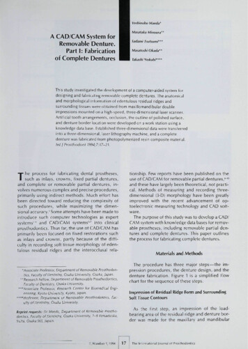
Yoshinobu Maeda*MasataliäA CAD/CAM System forRemovable Denture.Part I: Fabricationof Complete DenturesMitioura"Sadami Tsutsumi"*MasatoshiOkada"Takashi Nokubi**"'This study investigated the development of a computer-aided system fordesigning and fabricating removable complete dentures. The anatomicaland morphological information of edenfulous residual ridges andsurrounding tissues were obtained trom maxiliomandibular doubleimpressions mounted on a bigh-speed, three-dimensional laser scanner.Artificial tooth arrangements, occlusion, the outline of polished surface,and denture border location were developed on a work station using aknowledge data base. Established three-dimensional data were transferredinto a three-dimensional, laser lithography machine, and a completedenture was fabricated from pbotopolymerized resin composite material.¡nt! Prosthodont 1994:7:17-21.be process for fabricating dental prostheses,tionship. Few reports have been published on theuse of CAD/CAM for removable partial dentures,"-'"and these have largely been theoretical, not practical. Methods of measuring and recording threedimensional (3-D) morphology have been greatlyimproved with the recent advancement of optoelectronic measuring technology and CAD software.T such as inlays, crowns, fixed partial dentures,and complete or removable partial dentures, involves numerous complex and precise procedures,primarily using indirect metbods. Much effort hasbeen directed toward reducing the complexity ofsticb procedures, while maximizing fhe dimensional accuracy.' Some attempts have been made tointroduce such computer technologies as expertsystems--* and CAD/CAM systems' " into clinicalprosthodontics. Thus far, the use of CAD/CAM hasprimarily been focused on fixed restorations suchas inlays and crowns, partly because of tbe diffictjlty in recording soft tissue morphology of edentulous residual ridges and the interocclusal rela-The purpose of this study was to develop a CAD/CAM system with knowledge data bases for removable prostheses, including removable partial dentures and complete dentures. This paper outlinesthe process for fabricating complete dentures.Materials and Methods'Associate Frofessor, Department of Removable Prosthodontics, Faculty of Dentistry, Osaka University, Osaka, japan."Research Fellow, Depanment of Removable Prosthodontics,Faculty of Dentistry, Osaka University.""Associate Professor, Research Center foi Biomédical Engineering, Kyoto University, Kyoto, Japan.""Professor, Department of Removable Prosthodontics, Faculty of Dentistry, Osaka University.The procedure has three major steps—the impression procedures, the denture design, and tbedenture fabrication. Figure 1 is a simplified flowchart for the sequence of these steps.Impression of Residual Ridge Form and SurroundingSoft Tissue ContoursAs the first step, an impression of the load-Reprint reqtiests: Dr Maeda, Department of Removable Prosthodontics, faculty of Dentistry, Osaka University, l-B Yamadaoka, bearing area of the residual ridge and denture border was made for the maxillary and mandibularSuitä, Osaka 565, Japan.7, Number 1,199417The inlernational lournai of Prosthodontii
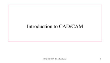
CAD/CAM Sy5tem for Removable DentunDouble ImpressionOptical ImpressionEngineering Work StationMandibular archLaser StereolithographFig 2 Double-I m pression technique; maxiiiary and mandibuiarimpressions were united intraoraily at the appropriate verticaiand horizontal relation.Fig 1 Flow chart tor the system.Fig 3 The 3-D iaser scanner ano conlroilerFig 4 The double-impression tray mounted on the 3-D iaserscanner and rod around which it can rotate 360 degrees.Fig 5 Exampies of recorded two-dimensional images for maxiiiary and mandibular impressions.The International louinal of Proslfiodonlics18Volume 7, Numberi, 1!"
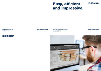
CAD/CAM System lor ReFig 6 (Left) Reconstructed 3-D images ot maxillary and mandibular impression surfaces and artificia i teeth with polishedsurface data trom fhe data base.Fig 7 (Below) The data of the artificiai feeth and poiishedsurface was matched with impression surface data.arches using a specially designed, double impression tray with conventional rubber base or siliconeimpression materials. The maxillary and mandibular impressions were connected at the appropriatevertical and horizontal relationship in the patient'smouth (Fig 2)." The double impression trays weretransferred and mounted on a 3-D laser scanner(Surflaser 500R, Unisn, Osaka, Japan) (Fig 3) thathas a rod around which the impressions can rotatea full 360 degrees. Two-dimensional images of theimpression surfaces were recorded by a spreadlaser beam and four charge-coupled device (CCD)cameras (Fig 4) while the impressions were movedlinearly. Sut ace images were obtained at three different angles for each maxillary and mandibularimpression around the rod, with the maximum accuracy of 0.05 mm (Fig 5). The six sets of data wereoverlapped, and 3-D coordinates describing the3-D surface morphology of the double impressionswere calculated. This calculation process was quiteeasily done using a personal computer as the impressions were connected to the same position ofthe rod at all times. These processes required approximately 15 to 20 minutes./ VGProjecor1iV"""1-JJL ]"TablePhritoiiolymerizingResinZ AM Elcvíll.jíHV.iiJFig 8 Exampleof use of3-D laser lithography; the obiecf wasfabricated in photopolymerizing resin on the table using a laserbeam from the projector, with mo iement in three dimensions.lapped and matched with those of the denturespace by moving points to the proper locations(Fig 6). Placement of artificial teeth was done toachieve proper stress distribution among denturesupporting tissues. "" Data for the artificial teethand the residual ridge relationship were reconstructed using the work station to be used in thedenture fabricating process (Fig 7).Denture Design (CAD): Arrangement of ArtificialTeelh and Border FormingDenture space data were transferred to an engineering work station (Titan-Vistra 800EX, Kubota,Tokyo, Japan). Data regarding fhe maxillary andmandibular complete dentures with standard artificial tooth arrangements were also obtained by theabove-mentioned method. Artificial teeth and denture surface data from the data base were over-7, Number 1,1994 ;Denture FabricationEither a numerically controlled (NC) milling machine or a 3-D laser lithography machine (Soup-400GASP, CMET, Tokyo, Japan) can be used (Fig 8).19af of Proslhodonln
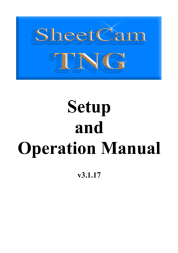
CAD/CAM System for Removable t entutFig 9 (Led) Tuvo outer shells (occiusal/polished surface and tissue surlai/-. partiof tiie denture were photopoiyi' '-" , (upper figures) and tooth-colored ycrylicresin composite was used to fili irit msideot the occiusal segment (tower ligure).Fig 10 (Right) Tissue-coiored, aulopolymerizing resin composite was poured intothe space between two outer sheils andfinished using conventional polishingmettiodstional methods."' Since scanning to image the maxillary and mandibular arch can be time consumingcompared to the time required to image a singlecrown or inlay, the present study attempted to havea functionally displaced soft tissue image for theload-bearing area using a conventional doubleimpression technique and the optical impressionmethod. This allowed the vertical height and horizontal relationships between the maxillae and mandibles to be determined simultaneously. As thedouble-impression tray can be rotated around therod attached to the 3-D scanning table, any undercut areaof the impression surface can be also easilydigitized and reconstructed. A work station is currently necessary for this process because of thedata size and computing speed required,A two- or three-dimensional simulation methodusing finite element analysis should be used toascertain the optimal position of artificial teeth interms of stress distribution for supporting tissue,"-' Occiusal adjustments and the refinemenf oftooth arrangements could also be performed withthe data obtained from the mandibular motion analyzer Ljsing optical systems with 6 degrees of freedom,'" The photopolymerized resin composite material for the artificial teeth and denture bases stillrequires additional studies regarding dimensionalaccuracy, biocompatibility, and color,A considerable amount of time is required tofinish the entire surface of the denture with theexisting lithography system. However, the time andcost for fabricating dentures, as well as the numberof patient visits, could be reduced to an acceptablelevel by future improvements and developments.Laser lithography has been developed and tjsed inindustries such as home electronics to create 3-Dmodels of new products based on paper or CADdesigns. Although it is possible to process a complete denture as a solid object using 3-D laser lithography, it is a time-consuming process. Therefore, only two outer shells (occlusal/polished partand tissue surface parti of the denture were photopolymerized in this study. Tooth-shade acrylic resincomposite was used to fill inside the occiusal portion (Fig 9), and the two segments of the denturesurfacewere connected using the reference points.Tissue-colored autopolymerizing resin compositewas then poured into the space, the excess wasremoved, and the shells were polished using conventional methods (Fig 10],DiscussionSeveral CAD/CAM systems throughout the worldhave been introduced to the field of dentistry, andsome of them have already been made commercially available for clinical use, As Stachniss andStoll" indicated, several problems must be overcome in any dental CAD/CAM system, includingthe impression, computer and software, material,tool/machine, and cost performance.To make inlays or crowns for a hard tissue(enamel and,'or dentin), an optical impressionmethod can be usedtodirectly digitize the cavity orpreparation morphology. For making impressionsof soft tissue, such as residual ridge mucosa, thevestibule, and the palate, there are several accepted concepts, eg, the mucostatic and the func-The International lournal of Prostliodontics20 7. NLmber1,1S
CAO/CAM System for Rcrrovabie DenturesAs the dentures fabricated in this study were not foractual patients, the ditnensionai accuracy of modeling by lithography shouid still be exatnined beforeactual clinical use.The photopolymerited resin composite patternfor a removable partial denture framework can becreated without the making of a refractory casf.Although there is still need for improvementswithin this CAD/CAM system, it has many possibilities for future clinical u e. The underlying theorycould also be applied to the process of makingsuperstructures for implant-supported prosthesesfor edentulous patients. A rational linkage of theCAD/CAM system, knowledge data base, and decision support systems should also be developed toincrease the efficacy of the entire system.3. MaedaY, Tsutsumi S, Minoura M, IkadaM, NokubiT, OkunoY. An expert system for designing removable partial dentures: The role of data base. J Osaka Univ Dent Sch1967;27:75-82.4. Beaumont A . Microcomputer-aided removabie partiai denture design: The next evolution. 1 Prosthet Dent 19e9;62:551-556.5. Duret E, Blouin L, Duret B. CAD-CAM in dentistry. Am DentAssoc 198B;11:71S-720.6. Rekow D. Computer-aided design and manufacturing indentistry: A review of the state of the art. j Prosthet Dent1967;5B;512-51S.7. Mollmann WH. Symposium Review, Proceedings oí Internationai Symposium on Computer Restoralions. Chicago:Quintessence, 1991:17-21.B. Becker W. CAD und CAM Möglichkeiten der Optimierung irder Totaiprothetik (II. Quintessenz Zahntech 1991;17]397-404.9. BeckerW. CAD und CAM Möglichkeiten der Optimierung inder lotaiprothetik (II). Quintessenz Zahntech 1991;17:10. BeckerW, CADund CAMMoglichkeiten der Optimierung inder Totaiprothetik (IM). Quintessenz Zahntech 1991;17:657-665.11. Nagakane K, Ohkawa S, Nagasawa T, Tsuru M. A procedurefor complete denture construction: Making bite-seated impression after maxillomandibular relation recording. J pnProsthodont Soc 1990;31:1053-1058.12. Maeda Y, Wood WW: Finite element method simulation ofbone résorption beneath a complete deniure Dent Res19e9;68:1370-1373,13. Maeda Y, Tsutsumi S, Qkada M, Idoji 5, Nokubi T, Okuno Y.Simulation of bone résorption in denture patients usingfinite element analysis. Part II: Influence or rehase, reline,occlusion, and rigidity of maxillary denture, 1 fpn Prosthodont Soc 1991; 35:211-216.14. Maeda Y,OkadaM, Enomoto K, Idoji S,Tsutsumi S, SogoM,Nokjbi T, Okuno Y, Three dimensional finite eiement analysis on removable dentures and edentuious mandibular morphoiogy. I Osaka Univ Dent Sch 1991 ;31:38-42.15. Stachniss BV, Stoll R. Computer Technologies in Dentistry.Computerized Restorations: Cerecand Other Methods, Proceedings of International Symposium on Computer Restorations. Chicago- Quintessence, 1991 33-50.16. Monteith BD. Management of loading forces on mandibuiardistai extension prostheses. Pari I: Evaiuation of concepts fordesign. ) Prosthet Dent19frl:S2:673-bei.17. Maeda V, Okada M, Mori T, Enomoto K, Sogo M, Qkuno Y.Dcveiopmontof mandibular tracking device with six degreesof freedom using optociectronic systems. J Osaka Univ DentSch 1992:32:45-50.ConclusionA prototype system for the fabrication of opposing complete dentures has been described and thecurrent and potential uses of both the system andthe philosophy were presented. Although improvements are essential to make this project clinicallyfeasible, the logical use of the concept holds a greatdeal of promise.AcknowledgmentsThe authors express their appreciation to Mr Muramoto ofUnisn Co, Osaka, lapan for his greai technical assistance to thisproject.References1. Shaveii hiM. The bioesthetics of complete porcelain rehabiiitation using the Sunrise ceramic system: A case report. Int Periodont Rest Dent 1990;10:257-279.2. Maeda Y, Tsutsumi S, Minoura M, Qkada M, Nokubi T,Okuno Y. An expert system for designing removable partialdentures. Preliminary report. Osaka Univ Dent Srh1985:25:79-84.7,Niimher1,199421The InternationaI oi Prosthodontics
abl e prostheses, including removabl partial den-tures and complete dentures. This paper outlines the process for fabricating complete dentures. Materials and Methods The procedure has three major steps—the im-pression procedures, the denture design, and tbe denture fabrication. Figure 1 is