Transcription
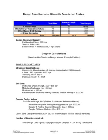
Design Specifications- Micropile Foundation SystemZoneTotal Piles1- Primary Area2-Radiotherapy Area (Linac Valuts)3-Shell Space & ED Canopy4- Bridge ConnectionTotal233708420387 pilesAverage Length(ft)6565656565 ftTotal Length1514545505460130026455 ftDesign Maximum Capacity:End-bearing Piles 280 kipsTension Piles 180Battered Piles 300 kips axial, 4 kips lateralGeopier Calculations(Based on GeoStructures Design Manual, Example Problem)ZONE 1: PRIMARY AREAStructural Specifications:Column J5- 4 bearing piles, @ bearing design load of 280 kips each4 Piles * 280 kips/pile 1120 kipsTributary Area 992 sfDistributed load 1.13 ksfSoil Data:Undrained Shear strength, c(u) 500 psfModulus of subgrade rxn. 50 pciMoist unit wt. 120 pcfRecommended allowable bearing capacity, shallow footings 2000 psfGeopier Design ValuesFor Silts and Clays, N 7 (Table 4.2 – Geopier Reference Manual)Allowable composite footing bearing pressure, qf 6000 psfGeopier & Footing Segment Capacity, Qqp 85 kipsGeopier Stiffness Modulus, Kp 210 pciLower Zone Design Parameter, Es 250 ksf (From Geopier Manual backup literature)Number of Geopiers required:Total Design Load [1120 kips] / [90 kips per Geopier] 12.4 Æ Try 12 GeopiersChris VorosConstruction Management OptionAppendix A--1--Cancer InstitutePenn State Hershey Medical Center
Footing Size and Composite Bearing Pressure:Est’d. Ftg size 1120 kips / 6 ksf 187 sf Æ Try 14’ x 14’ ftg.Actual Ftg. Size 196 sfComposite bearing pressure, q 1120 kips / 196 sf 5.7 ksf 5714 psfUpper Zone Settlement:Area Ratio, R(a) of footing area covered by Geopiers (30” diameter Æ 4.91 sf)R(a) 12 Geopiers * 4.91 / 196 sf 0.30 30.06%Stress Ratio (Geopier to Matrix soil stiffness ratio)Matrix soil modulus, Km [2000 psf] / [144 in 2 per ft 2] / [1 inch] 13.9 pciStress Ratio, Rs Kp / Km 210 pci / 13.9 pci 15.12Maximum stress on Geopier:q(qp) q * Rs / (Ra*Rs –Ra 1) [5714*15.12 ] / [.30*15.12 - .30 1] 16482.7psfUpper Zone Settlement Calc:S(uz) q(qp) / Kp 16482.7 / 144 / 210 0.545 inchesLower Zone Settlement:Allowable LZ Settlement, S(lz) 1.0” – 0.545” 0.455 inchesFooting width, B 14’, UZ LZ 2B 28 feetTry 10’ Shaft LengthUZ shaft length 1 diameter prestress zone 10’ 30 inches 12.5 feetLZ 28’ – 12.5’ 15.5 feetLower Zone Stress, qlz at center of Lower Zone (using Westergaard Stress Dist.)Center of LZ depth UZ (LZ / 2) 12.5’ (15.5 / 2) 20.25 feetf(B) 20.25’ / 14’ 1.45From Westergaard- approximately 14% of composite footing bearing pressureQ(lz) 0.14 * 5174 776 psf .776 ksfLower Zone SettlementS(lz) q(lz) / Es * LZ * 12 in/ft 0.776 / 250 * 14 * 12 0.537 in 0.455 inSettlement greater than 1”, however still assume 10’ shaft length for purposes ofthis investigationNumber of Geopiers required:31’ x 31’ Bay @ 10’ x 8’ Spacing Æ 36,733 sf / 992 * 12 444 GeopiersNot all bays 31’ x 31’, Therefore use spacing standard to determine numberrequired.Per Grid Plan Æ 419 Total Geopier ElementsChris VorosConstruction Management OptionAppendix A--2--Cancer InstitutePenn State Hershey Medical Center
ZONE 2: RADIOTHERAPY ENCLOSURE70 Piles * 280 kips/pile 19600 kipsTotal Area 6000 sfDistributed load 3.26 ksfNumber of Geopiers required:Total DL [19600 kips] / [90 kips per Geopier] 217 Æ Try 220 Geopiers@ 5.5’ x 5.5’ Nominal Spacing Æ 228 Geopiers TotalZONE 3: SHELL SPACE84 Piles * 280 kips/pile 23520 kipsTotal Area 13811 sfDistributed load 1.7 ksfNumber of Geopiers required:Total DL [23520 kips] / [90 kips per Geopier] 261 Æ Try 260 GeopiersThe nature of this area requires a second look: 24 of the piles are located in a gradebeam at the South end, all of which are battered (angled). However, 260 Geopiers willstill be installed due to ambiguity in how this load distributes over a mat slab.@ 8’ x 7’ Nominal Spacing Æ 269 Geopiers TotalGeopier Summary:Zone 1 419Zone 2 228Zone 3 269Total 916 Geopier ElementsChris VorosConstruction Management OptionAppendix A--3--Cancer InstitutePenn State Hershey Medical Center
Mat Slab Thickness Calculations(Based on Principles of Engineering, Sixth Edition, Braja M. Das)Feasibility Analysis: (uses foundation wall depth of 20’ (typ.)Soil Data: (from Geotechnical Report)Undrained Shear strength, c(u) 500 psfMoist unit wt. 120 pcfD(f) 20’ ?Factor of Safety (shear) 1.5 (typ.)Φ 22 degrees (internal angle of friction)P 1120 kips (from above)D(f) calculation: q(net, ultimate) 5.14*c(u)*[1 0.195B/L]*[1 0.4D(f)/B]Zone 1: Using q(net, u) P 1120 kips:Bay: 31’ x 31’ ftg. (B x L) (typical)Using D(f) 22’ Æ3942.96 psf 1129 psfOK- Determine Actual ThicknessMat Slab Thickness DeterminationThickness Calculation: ΦV(c) Φ4*sqrt(f’c)*b(0)*dΦV(c) Pf’c 4000 psi (based on structural specifications)b 2(b d) 2(c d)Φ 0.85 (typical, punching shear)Zone 1: Distributed Load 1129 psfWall Depth 20’D(f) ?Column J-4: P 1120 kipsBase Plate Dim’s. 22” x 22” (b x c)Æ d 27” 1” (dia. of reinforcing, 2 ways) 3” (cover) 33” 2’-9” slabZone 2: Distributed Load 3260 psfWall Depth 20’D(f) ?Æ d 49” 2” (dia. of reinforcing, 2 ways) 3” (cover) 54” 4’-6” slab(Note, since no column point loads are in this area, b and c are assumed to belargest of base plates dimensions 26” x 30”)Chris VorosConstruction Management OptionAppendix A--4--Cancer InstitutePenn State Hershey Medical Center
Zone 3: Distributed Load Not typicalWall Depth 20’D(f) ?Pile Cap Q.5, 7.3: P 560 kipsBase Plate Dim’s. 40.5” x 81” (b x c) (estimated)Æ d 9” 1” (dia. of reinforcing, 2 ways) 3” (cover) 13” Æ Use 15” slabChris VorosConstruction Management OptionAppendix A--5--Cancer InstitutePenn State Hershey Medical Center
Chris VorosConstruction Management OptionAppendix A--6--Cancer InstitutePenn State Hershey Medical tput562.73Qty.UnitC.Y.1.986 C.Y.0.32 C.Y.LaborHrs 228.00 84.00 144.00 0.00MaterialsUnit Cost 57.10 0.00 50.00 7.10Labor UnitCost56.5DailyOutputUnitC.Y.1.986 C.Y.Ea.LaborHrs 228.00 84.00 144.00MaterialsUnit Cost 100.00 0.00 100.00Labor UnitCostAssume: Two crews working on mat slab pour 2x labor costsGeopier cost/element based on rough estimate provided by Geopier professionalPile Installation based on contract value provided by GilbaneTotals53815381916Qty.FOUNDATION CONCRETE COSTS- PROPOSED MAT SLABTotalsStructural concrete, in place,foundation mat, over 20 C.Y., includes3310-240- forms(4 uses), reinforcing steel, andfinishing4050Geopier InstallationStructural concrete, ready mix, normal3310-220- weight, 4000 PSI, includes materialonly0300CSI CodePile InstallationStructural concrete, placing, pile caps,3310-700- pumped, 6 C.Y. to 10 C.Y., includesvibrating, excludes material3900Structural concrete, in place,foundation mat, over 20 C.Y., includes3310-240- forms(4 uses), reinforcing steel, andfinishing4050Structural concrete, ready mix, normal3310-220- weight, 4000 PSI, includes materialonly0300CSI CodeFOUNDATION CONCRETE COSTS- EXISTING SLAB ON GRADE 0.42 0.00 0.42EquipmentUnit Cost 4.18 0.00 0.42 3.76EquipmentUnit Cost 1,003.42 84.00 244.42 675.00Total 289.28 84.00 194.42 10.86Total 2,698,056.50 497,742.50 1,582,014.00 618,300.00Total,incl. O&P 941,552.82 1,250,000.00 294,705.00 637,816.00 9,031.82Total,incl. O&P
Design Specifications- Micropile Foundation System Zone Total Piles Average Length (ft) Total Length 1- Primary Area 233 65 15145 2-Radiotherapy Area (Linac Valuts) 70 65 4550 3-Shell Space & ED Canopy 84 65 5460 4- Bridge Connection 20 65 1300 Total 387 piles 65 ft 26455 ft Design Maximum Capacity: End-bearing Piles 280 kips