Transcription
NX 12 forEngineering Design
ContentsPREFACE . 1CHAPTER 1 – INTRODUCTION . 21.1 PRODUCT REALIZATION PROCESS .21.2 BRIEF HISTORY OF CAD/CAM DEVELOPMENT .31.3 DEFINITION OF CAD/CAM/CAE .51.3.1 Computer Aided Design – CAD . 51.3.2 Computer Aided Manufacturing – CAM . 51.3.3 Computer Aided Engineering – CAE. 51.4. SCOPE OF THIS TUTORIAL .6CHAPTER 2 – GETTING STARTED . 82.1 STARTING AN NX 12 SESSION AND OPENING FILES .82.1.1 Start an NX 12 Session. 82.1.2 Open a New File . 92.1.3 Open a Part File . 102.2 PRINTING, SAVING AND CLOSING FILES .122.2.1 Print an NX 12 Image . 122.2.2 Save Part Files . 122.2.3 Close Part Files. 132.2.4 Exit an NX 12 Session . 142.3 NX 12 INTERFACE .142.3.1 Mouse Functionality . 142.3.2 NX 12 Gateway . 172.3.3 Geometry Selection . 212.3.4 User Preferences . 222.3.5 Applications . 252.4 LAYERS .262.4.1 Layer Control . 26I
2.4.2 Commands in Layers . 272.5 COORDINATE SYSTEMS .292.5.1 Absolute Coordinate System . 292.5.2 Work Coordinate System . 292.5.3 Moving the WCS . 292.6 TOOLBARS.30CHAPTER 3 – TWO DIMENSIONAL SKETCHING. 333.1 OVERVIEW .333.2 SKETCHING ENVIRONMENT .343.3 SKETCH CURVE TOOLBAR .353.4 CONSTRAINTS TOOLBAR .373.5 EXAMPLES .403.5.1 Arbor Press Base . 403.5.2 Impeller Lower Casing . 443.5.3 Impeller . 483.6 EXERCISES .503.6.1 Circular Base . 503.6.2 Sketching of a Holder . 50CHAPTER 4 – THREE DIMENSIONAL MODELING . 514.1 TYPES OF FEATURES .514.1.1 Primitives . 524.1.2 Reference Features . 524.1.3 Swept Features . 534.1.4 Remove Features . 544.1.5 Extract Features . 544.1.6 User-Defined features . 554.2 PRIMITIVES .554.2.1 Model a Block . 554.2.2 Model a Shaft . 57II
4.3 REFERENCE FEATURES.604.3.1 Datum Plane . 604.3.2 Datum Axis . 614.4 SWEPT FEATURES .624.5 REMOVE FEATURES.674.5.1 General Hole . 674.5.2 Pocket . 694.5.3 Slot . 704.5.4 Groove . 704.6 FEATURE OPERATIONS .704.6.1 Edge Blend . 704.6.2 Chamfer . 714.6.3 Thread . 714.6.4 Trim Body . 724.6.5 Split Body . 734.6.6 Mirror . 734.6.7 Pattern. 734.6.8 Boolean Operations . 744.6.9 Move. 754.7 EXAMPLES .774.7.1 Hexagonal Screw . 774.7.2 Hexagonal Nut . 804.7.3 L-Bar . 834.7.4 Rack . 874.7.5 Impeller . 924.8 STANDARD PARTS LIBRARY .954.9 SYNCHRONOUS TECHNOLOGY .964.10 EXERCISES .1004.10.1 Rocker Arm . 1004.10.2 Holder . 100III
4.10.3 Impeller Upper Casing . 1014.10.4 Die-Cavity . 102CHAPTER 5 – DRAFTING . 1045.1 OVERVIEW .1045.2 CREATING A DRAFTING .1055.3 DIMENSIONING .1105.4 SECTIONAL VIEW .1125.5 PRODUCT AND MANUFACTURING INFORMATION .1145.6 EXAMPLE .1175.7 EXERCISE .121CHAPTER 6 – ASSEMBLY MODELING . 1226.1 TERMINOLOGY .1226.2 ASSEMBLING APPROACHES .1236.2.1 Top-Down Approach. 1236.2.2 Bottom-Up Approach . 1236.2.3 Mixing and Matching . 1246.3 ASSEMBLY AND CONSTRAINT NAVIGATORS .1246.4 MATING CONSTRAINTS .1246.5 EXAMPLE .1256.5.1 Starting an Assembly . 1266.5.2 Adding Components and Constraints . 1286.5.3 Exploded View . 1386.6 EXERCISES .1426.6.1 Arbor Press . 1426.6.2 Butterfly Valve . 1426.6.3 Jackscrew . 146CHAPTER 7 – FREEFORM SURFACE MODELING . 1487.1 OVERVIEW .148IV
7.1.1 Creating Freeform Features from Points . 1487.1.2 Creating Freeform Features from Section Strings . 1497.1.3Creating Freeform Features from Faces . 1507.2 FREEFORM FEATURE MODELING .1507.2.1 Modeling with Points . 1517.2.2 Modeling with a Point Cloud . 1527.2.3 Modeling with Curves . 1547.2.4 Modeling with Curves and Faces . 1567.3 EXERCISES .1587.3.1 An Exercise on Curves . 1587.3.2 An Exercise on Surfaces. 1597.3.3 Design a Computer Mouse . 1607.3.4 Design a Sport Water Bottle . 160CHAPTER 8 – FINITE ELEMENT ANALYSIS . 1618.1 OVERVIEW .1618.1.1 Element Shapes and Nodes . 1618.1.2 Solution Steps . 1638.1.3 Simulation Navigator . 1648.2 SIMULATION CREATION.1648.3 MATERIAL PROPERTIES .1678.4 MESHING .1698.5 LOADS .1708.6 BOUNDARY CONDITIONS .1718.7 RESULT AND SIMULATION .1728.7.1 Solving the Simulation . 1728.7.2 FEA Result . 1748.7.3 Simulation and Animation . 1778.8 EXERCISES .1808.8.1 Arbor Press Bar . 1808.8.2 Rocker Arm . 181V
CHAPTER 9 – MANUFACTURING . 1829.1 GETTING STARTED .1829.1.1 Creation of a Blank . 1829.1.2 Setting Machining Environment . 1849.1.3 Operation Navigator . 1859.1.4 Machine Coordinate System (MCS) . 1859.1.5 Geometry Definition . 1869.2 CREATING OPERATION .1879.2.1 Creating a New Operation . 1879.2.2 Tool Creation and Selection . 1889.2.3 Tool Path Settings . 1919.2.4 Step Over and Scallop Height . 1929.2.5 Depth Per Cut . 1939.2.6 Cutting Parameters . 1939.2.7 Avoidance. 1949.2.8 Speeds and Feeds . 1959.3 PROGRAM GENERATION AND VERIFICATION .1979.3.1 Generating Program . 1979.3.2 Tool Path Display . 1979.3.3 Tool Path Simulation . 1989.3.4 Gouge Check . 2009.4 OPERATION METHODS .2019.4.1 Roughing . 2019.4.2 Semi-Finishing . 2019.4.3 Finishing Profile . 2049.4.4 Finishing Contour Surface . 2089.4.5 Flooring . 2129.5 POST PROCESSING .2159.5.1 Creating CLSF. 2169.5.2 Post Processing . 217VI
PREFACENX is one of the world’s most advanced and tightly integrated CAD/CAM/CAE productdevelopment solution from Siemens PLM Software. Spanning the entire range of productdevelopment, NX delivers immense value to enterprises of all sizes. It simplifies complex productdevelopment, thus speeding up the process of introducing products to the market.The NX software integrates multidisciplinary principles, conceptual design, 3D modeling,documentation, engineering analysis, graphic simulation, and concurrent engineering. Thesoftware has powerful hybrid modeling capabilities by integrating constraint-based featuremodeling and explicit geometric modeling. In addition to modeling standard geometry parts, itallows the user to design complex freeform shapes such as airfoils and manifolds. It also mergessolid and surface modeling techniques into one powerful toolset.This self-guided tutorial provides a step-by-step approach for users to learn NX 12. It is intendedfor those with no previous experience with NX. However, users of previous versions of NX mayalso find this tutorial useful for them to learn the new user interfaces and functions. The user willbe guided from starting an NX 12 session to creating models and designs that have variousapplications. Each chapter has components explained with the help of various dialog boxes andscreenshots. These components are later used in the assembly modeling, machining and finiteelement analysis. The files of components are also available online to download and use. We firstreleased the tutorial for Unigraphics 18 and later updated for NX 2 followed by the updates forNX 3, NX 5, NX 7, NX 9 and NX 10. This write-up further updates to NX 12.Our previous efforts to prepare the NX self-guided tutorial were funded by the National ScienceFoundation’s Advanced Technological Education Program and by the Partners of theAdvancement of Collaborative Engineering Education (PACE) program.If you have any questions or comments about this tutorial, please email Ming C. Leu atmleu@mst.edu or Wenjin Tao at wt6c2@mst.edu. The models and all the versions of the tutorialare available at http://web.mst.edu/ mleu.NX 12 for Engineering Design1Missouri University of Science and Technology
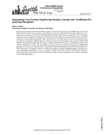
CHAPTER 1 – INTRODUCTIONThe modern manufacturing environment can be characterized by the paradigm of deliveringproducts of increasing variety, smaller batches and higher quality in the context of increasingglobal competition. Industries cannot survive worldwide competition unless they introduce newproducts with better quality, at lower costs and with shorter lead-time. There is intenseinternational competition and decreased availability of skilled labor. With dramatic changes incomputing power and wider availability of software tools for design and production, engineers arenow using Computer Aided Design (CAD), Computer Aided Manufacturing (CAM) and ComputerAided Engineering (CAE) systems to automate their design and production processes. Thesetechnologies are now used every day for all sorts of different engineering tasks. Below is a briefdescription of how CAD, CAM, and CAE technologies are being used during the productrealization process.1.1 PRODUCT REALIZATION PROCESSThe product realization process can be roughly divided into two phases: design and manufacturing.The design process starts with identification of new customer needs and design variables to beimproved, which are identified by the marketing personnel after getting feedback from thecustomers. Once the relevant design information is gathered, design specifications are formulated.A feasibility study is conducted with relevant design information and detailed design and analysesare performed. The detailed design includes design conceptualization, prospective productdrawings, sketches and geometric modeling. Analysis includes stress analysis, interferencechecking, kinematics analysis, mass property calculations and tolerance analysis, and designoptimization. The quality of the results obtained from these activities is directly related to thequality of the analysis and the tools used for conducting the analysis.The manufacturing process starts with the shop-floor activities beginning from productionplanning, which uses the design process drawings and ends with the actual product. Processplanning includes activities like production planning, material procurement, and machineselection. There are varied tasks like procurement of new tools, NC programming and qualitychecks at various stages during the production process. Process planning includes planning for allNX 12 for Engineering Design2Missouri University of Science and Technology
the processes used in manufacturing of the product. Parts that pass the quality control inspectionsare assembled functionally tested, packaged, labeled, and shipped to customers.A diagram representing the Product Realization Process (Mastering CAD/CAM, by Ibrahim Zeid,McGraw Hill, 2005) is shown below.1.2 BRIEF HISTORY OF CAD/CAM DEVELOPMENTThe roots of current CAD/CAM technologies go back to the beginning of civilization whenengineers in ancient Egypt recognized graphics communication. Orthographic projection practicedtoday was invented around the 1800s. The real development of CAD/CAM systems started in the1950s. CAD/CAM went through four major phases of development in the last century. The 1950swas known as the era of interactive computer graphics. MIT’s Servo Mechanisms Laboratorydemonstrated the concept of numerical control (NC) on a three-axis milling machine. Developmentin this era was slowed down by the shortcomings of computers at the time. During the late 1950sNX 12 for Engineering Design3Missouri University of Science and Technology
the development of Automatically Programmed Tools (APT) began and General Motors exploredthe potential of interactive graphics.The 1960s was the most critical research period for interactive computer graphics. Ivan Sutherlanddeveloped a sketchpad system, which demonstrated the possibility of creating drawings andaltercations of objects interactively on a cathode ray tube (CRT). The term CAD started to appearwith the word ‘design’ extending beyond basic drafting concepts. General Motors announced theirDAC-1 system and Bell Technologies introduced the GRAPHIC 1 remote display system.During the 1970s, the research efforts of the previous decade in computer graphics had begun tobe fruitful, and potential of interactive computer graphics in improving productivity was realizedby industry, government and academia. The 1970s is characterized as the golden era for computerdrafting and the beginning of ad hoc instrumental design applications. National ComputerGraphics Association (NCGA) was formed and Initial Graphics Exchange Specification (IGES)was initiated.In the 1980s, new theories and algorithms evolved and integration of various elements of designand manufacturing was developed. The major research and development focus was to expandCAD/CAM systems beyond three-dimensional geometric designs and provide more engineeringapplications.The present day CAD/CAM development focuses on efficient and fast integration and automationof various elements of design and manufacturing along with the development of new algorithms.There are many commercial CAD/CAM packages available for direct usages that are user-friendlyand very proficient.Below are some of the commercial packages in the present market. Solid Edge, AutoCAD, Inventor and TurboCAD are some affordable CAD softwaresystems. NX, Pro-E, CATIA and SolidWorks are high-end modeling and designing softwaresystems that are costlier but more powerful. These software systems also have computeraided manufacturing and engineering analysis capabilities. Onshape and Fusion 360 are cloud based CAD software, which provide CAD capabilitiesvia user’s browser.NX 12 for Engineering Design4Missouri University of Science and Technology
ANSYS, ABAQUS, NASTRAN and COMSOL are packages mainly used for CAEpurposes.1.3 DEFINITION OF CAD/CAM/CAEFollowing are the definitions of some of the terms used in this tutorial.1.3.1 Computer Aided Design – CADCAD is technology concerned with using computer systems to assist in the creation, modification,analysis, and o
engineers in ancient Egypt recognized graphics communication. Orthographic projection practiced today was invented around the 1800s. The real development of CAD/CAM systems started in the 1950s. CAD/CAM went through four major phases of development in the last century. The 195