Transcription
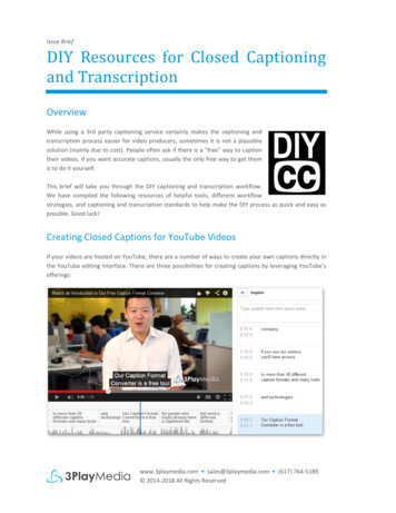
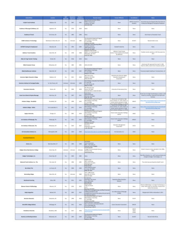
Specification sheetCHPCTransferswitch closedtransition125 - 800 AmpDescription Features The Cummins series CHPC PowerCommandautomatic transfer switch monitors the primary powersource, signals the generator to start upon loss ordestabilization of utility power, and then automaticallytransfers the load to the generator. Once the utilitypower source becomes available and stable, theCHPC will return the load to the primary sourcewithout power interruption by temporarily parallelingboth sources for less than 100 msecs.Designed and constructed specifically for closedtransition operation, this clean sheet, revolutionarydesign incorporates the innovative High EnduranceMechanism (HEM) for uncompromising reliability withthe proven PowerCommand Microprocessor Control.UL-listed 30-cycle ratings - CHPC is listed for shorttime ratings of 25,000 amps at 10 cycles for 125-260amps, 30,000 amps at 30 cycles for 300-600 amps,and 42,000 amps at 30 cycles for 800 amps.PowerCommand control - A standard, fully featuredmicroprocessor-based control. Software-enabledfeatures, settings, and adjustments are available forease of setup and accuracy. Optically isolated logicinputs and high isolation transformers for AC powerinputs provide high-voltage surge protection.Manual operation - Manual operating handles andstored energy transfer mechanism allow effective,manual operation of the CHPC. An external operatoris available as an option for dead front manualoperation. Manual operation of the CHPC can only beperformed in the open transition transfer mode.Main contacts - Heavy-duty silver allow contacts andmulti-leaf arc chutes are rated for total systemtransfer.Easy service/access - Plug connections, doormounted controls, ample access space, andcompatible terminal markings allow for easy service.Product lines, accessories and services Cummins offers a wide range of accessories andservices to suit your requirementsWarranty and service - Backed by a comprehensivewarranty and worldwide distributor network.power.cummins.com 2017 Cummins Inc. S-1437 (10/17)
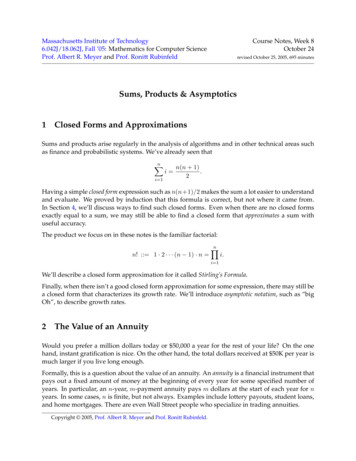
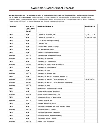
Transfer switch mechanism CHPC has earned the industry’s highest UL-listed short-time ratings. At480 volts, 125-260 amp switches are rated at 25,000 for 10 cycles, 300600 are rated at 30,000 for 30 cycles, and 800 is rated at 42,000 for 30cycles. Blow-on contactor allows for high survivability in fault current conditions. Simultaneous make-before-break contactor action is used for 2-pole, 3pole, and 4-pole switches. On 4-pole/switched neutral switches, this actionalso prevents the objectionable ground currents and nuisance ground faulttripping that can result from overlapping neutral designs. The CHPC will operate as an open transition transfer switch whentransferring a load from a dead source to a live source. A mechanicalinterlock eliminates the possibility of source-to-source connection when theswitch is manually operated. When operated in closed transition mode the mechanical interlock isdisabled by the controller. This allows the CHPC to connect both sourcestogether for a period not to exceed 100 msecs, providing a seamlesstransfer of the load between two live sources. Long-life, high pressure, silver alloy contacts resist burning and pitting.Separate arcing surfaces further protect the main contacts. Contacts aremechanically held in both normal and emergency positions for reliable,quiet operation. Superior arc interruption is accomplished through multiple leaf arc chutesthat cool and quench the arcs. Barriers separate the phases and preventinter-phase flashover.SpecificationsVoltage ratingTransfer switches up to 600 VAC.Amperage ratingTransfer switches are rated from 125 to 800 amperes.Frequency ratingTransfer switches are rated to operate at 50 or 60 Hertz.Neutral barA full current-rated neutral bar with lugs is standard on enclosed 2 and 3-poletransfer switches.Auxiliary contactsTwo switch position contacts rated at 10A Continuous and 250 VAC maximum (onefor each source) are provided for customer use.Operating temperature-40 F (-40 C) to 140 F (60 C)Storage temperature-40 F (-40 C) to 140 F (60 C)HumidityUp to 95% relative, non-condensingAltitudeUp to 10,000 ft (3,000 m) without de-ratingSurge withstand ratingsControl system surge-tested for location category B3, per IEEE C62.41 and IEEEC62.45. Also meets European standard EN61000-4-5.Total transfer time(source to-source)Will not exceed 6 cycles at 60 Hz when operated as an in phase monitor basedopen transition transfer switchpower.cummins.com 2017 Cummins Inc. S-1437 (10/17)
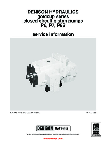
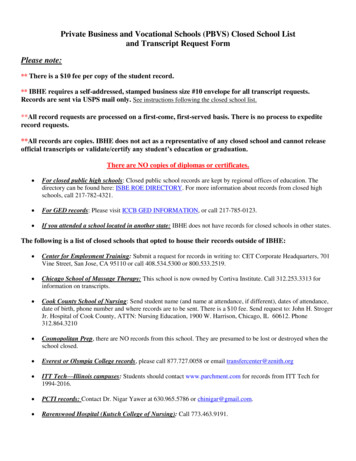
HEM power cassette Cassette design ensures that all phases and neutral areswitched at the same speed, providing true four poleoperation. Encapsulated contactor design increases phase tophase isolation and reduces possibility of arcingbetween phases. New design eliminates a common failure point in manytransfer switches by not using electrical connectionsmade of braided metal in the mechanism’s current path. Simple design has fewer parts reducing themechanism’s potential for failure.The innovative design of the High Endurance MechanismThe High Endurance Mechanism (HEM) is designed to ride through a fault condition undamaged, retaining its capability tocarry 100% of its rated load. Magnetic forces developed during a fault cause a conventional transfer switch’s contacts toblow open, producing destructive arcing that often results in extensive internal damage to the switch. Typically after aconventional switch experiences a fault, its contacts, arc chutes and in some cases its controller needs to be replaced. TheHEM uses that same magnetic energy to hold the contacts closed during a fault, practically eliminating arcing, contactdamage, and performance degradation. That means the HEM does not require contact maintenance to continue to carryrated current without overheating. The HEM can survive multiple faults of the magnitude listed on the nameplate as theWithstand and Closing Current Ratings (WCR). This novel blow-on technology means that there will be no costly repairs orinconvenient downtime after a fault.power.cummins.com 2017 Cummins Inc. S-1437 (10/17)
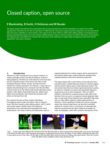
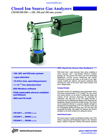
PowerCommand microprocessor controlPowerCommand controls are microprocessor based and developed specifically for automatic transfer switch operation. Thecontrol provides features and options useful for most applications. Flash memory is used to store control settings. Thecontents of the memory are not lost even if power to the controller is lost. There is also an on-board battery to maintain thereal-time clock setting and the engine start time delay. Control features include:Level 2 controlOpen transition (in-phase transition)Delayed transition (programmed transition)Closed transition (momentary overlap)Utility-to-genset applicationsSoftware adjustable time delays: Engine start: 0 to 120 sec Transfer normal to emergency: 0 to 120 sec Retransfer emergency to normal: 0 to 30 min Engine stop: 0 to 30 min Programmed transition: 0 to 60 secUndervoltage sensing - 3-phase normal, 3-phaseemergency Pickup: 85% to 98% of nominal voltage Dropout: 75% to 98% of pickup setting Dropout time delay: 0.1 to 1.0 secOvervoltage sensing - 3-phase normal, 3-phaseemergency Dropout: 105% to 135% of nominal voltage Pickup: 95% to 99% of dropout setting Dropout time delay: 0.5 to 120 secOver/under frequency sensing Pickup: 5% to 20% of nominal frequency Dropout: 1% beyond pickup Dropout time delay: 0.1 to 15.0 secVoltage imbalance sensing Dropout: 2% to 10% Pickup: 90% of dropout Time delay: 2.0 to 20.0 secPhase rotation sensing Time delay: 100 msecLoss of single phase detection Time delay: 100 msecProgrammable genset exerciser - Eight events/scheduleswith or w/o loadBasic indicator panel Source available/connected LED indicators Test/exercise/bypass buttons Digital display - standard Analog bargraph metering - optionalDate/time-stamped event recording - 50 eventsLoad sequencing (optional with Network CommunicationsModule)power.cummins.com 2017 Cummins Inc. S-1437 (10/17)
Time-delay functionsEngine start: Prevents nuisance genset starts in the event of momentary power system variation or loss. Not included inutility-to-utility systems.Transfer normal to emergency: Allows genset to stabilize before application of load. Prevents power interruption if normalsource variation or loss is momentary. Allows staggered transfer of loads in multiple transfer switch systemsRetransfer emergency to normal: Allows the utility to stabilize before retransfer of load. Prevents needless powerinterruption if return of normal source is momentary. Allows staggered transfer of loads in multiple transfer switch systemsEngine stop: Maintains availability of the genset for immediate reconnection in the event that the normal source fails shortlyafter retransfer. Allows gradual genset cool down by running unloaded. Not included in utility-to-utility systems.Delayed (programmed) transition: Transfers load to neutral position, disconnected from sources, to allow inductive loadvoltages to decay.Fail to disconnect timer: Signals external device to disconnect either the genset or utility to prevent extended operation inparallel with the utility.User interfacesControl optionsBasic interface panelLED indicators provide at-a-glance source and transferswitch status for quick summary of system conditions. Testand Override buttons allow delays to be bypassed for rapidsystem checkout.Digital display (M018)The digital display provides a convenient method formonitoring load power conditions, adjusting transfer switchparameters, monitoring PowerCommand Network status, orreviewing transfer switch events. Password protection limitsaccess to adjustments to authorized personnel. The digitaldisplay comes standard with the Level 2 PowerCommandmicroprocessor control, and is optional with the Level 1Control.Relay signal module (M023)Provides an adjustable transfer pre-signal time delay of 0 to60 seconds to prevent interruption of power during elevatoroperation. Relay outputs include: Source 1 Connected andAvailable, Source 2 Connected and Available, Not in Auto,Test/Exercise Active, Failed to Disconnect, Failed toSynchronize, Failed to Transfer/Retransfer, and Transfer presignal (elevator signal).Loadshed (M007)Removes the load from the emergency power source bydriving the transfer switch to the neutral position whensignaled remotely. Transfers load back to the emergencysource when the signal contacts open. Immediate retransferto the preferred source when it is re-established.PowerCommand network interface (M031)Provides connection to the PowerCommand network.LonWorks compatible for integration into customermonitoring strategy.Load power and load current monitoring (M022)Measures load phase and neutral, current, power factor, realpower (kW) and apparent power (kVA). Warns of excessiveneutral current resulting from unbalanced or nonlinear loads.Minimum detectable current level is 3%.User interface optionsFront panel security key (M017)Front panel access can be locked out using this option.Prevents unauthorized transfers or testing. Preventsunauthorized adjustments via the digital display.Analog bar graph meter (D009)An LED bar graph display provides easy to read indicationfor Normal and Emergency voltages and frequencies, loadcurrents, power factor, and kilowatts. Green, amber, andred LED's provide at-a-glance indication of systemacceptability. Available as an option with the Level 2PowerCommand microprocessor control.External operation handle (N038)Dead-front manual operating handle for safe manualoperation. Can be operated while the switch is energized.Manual operation of the CHPC can only be performed inthe open transition transfer mode. Manual operation of theOHPC can only be performed in the open transition transfermode* Note: Some options may not be available on all models - consult factory for availability.power.cummins.com 2017 Cummins Inc. S-1437 (10/17)
UL withstand and closing ratingsThe transfer switches listed below must be protected by circuit breakers or fuses. Referenced drawings include detailedlistings of specific breakers or fuse types that must be used with the respective transfer switches. Consult with yourdistributor/dealer to obtain the necessary drawings. Withstand and Closing Ratings (WCR) are stated in symmetrical RMSamperes.UL-listed specific breaker ratingsMCCB protectionCurrent limited breaker protectionTransferswitch ampereWCR @ voltsmax withspecificmanufacturersMCCBsWith specificcurrentlimitingbreakers(CLB)125, 150,225, 26042,000 @ 48030,000 @ 600300, 400, 60080065,000 @ 48050,000 @ 60085,000 @ 48065,000 @ 600Max MCCBratingsDrawingreference500 AA048E9411200 AA048E9431400 AA048E945200,000 @ 480200,000 @ 600200,000 @ 480200,000 @ 600200,000 @ 480200,000 @ 600MaxCLBrating500 ADrawing referenceA048J5561200 AA048J5581400 AA048J560UL-listed fuse protection ratingsTransferswitchampereWCR @ voltsmax. withcurrent limitingfusesMax fuse, size and typeDrawing reference400 A class J, T125,150, 225,260200,000 @ 600200 A class RK1A048E941100 A class RK5300, 400, 600200,000 @ 6001200 A class, L, TA048E943600 A class, J, RK1, RK5800200,000 @ 6002000 A class LA048E9452000 A class TUL-listed 3 cycle and short-time ratingsTransfer switchampere125, 150, 225, 260300, 400, 600800WCR @ volts max 3cycle ratingShort-time ratings@ 480 voltsMax MCCB ratingDrawing reference25,000 @ 48025,000 for 10 cycles500 AA048E94130,000 for 30 cycles1200 AA048E94342,000 for 30 cycles1400 AA048E94518,000 @ 60035,000 @ 48022,000 @ 60065,000 @ 48065,000 @ 600power.cummins.com 2017 Cummins Inc. S-1437 (10/17)
EnclosuresThe wall-mounted transfer switch and control are mounted in a key-locking enclosure. Wire bend space complies with2005 NEC.Dimensions - transfer switch in UL type 1 enclosureDepthAmpratingHeightWidthDoor closedDoor openWeight 3-poletypeinmminmminmminmmlbkgOutlinedrawing125, 150,225, 26049124525.0563519.64974411182311050500-35
60 seconds to prevent interruption of power during elevator operation. Relay outputs include: Source 1 Connected and Available, Source 2 Connected and Available, Not in Auto, Test/Exercise Active, Failed to Disconnect, Failed to Synchronize, Failed to Transfer/Retransfer, and Transfer pre-signal (elevator signal). Loadshed (M007)