Transcription
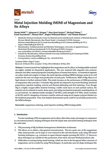
metalsArticleMetal Injection Molding (MIM) of Magnesium andIts AlloysMartin Wolff 1, *, Johannes G. Schaper 1 , Marc René Suckert 2 , Michael Dahms 2 ,Frank Feyerabend 1 , Thomas Ebel 1 , Regine Willumeit-Römer 1 and Thomas Klassen 3123*Helmholtz-Zentrum Geesthacht, Centre for Materials and Coastal Research, Institute of Materials Research,Division Metallic Biomaterials, Max-Planck Straße 1, Geesthacht D-21502, Germany;johannes.schaper@hzg.de (J.G.S.); frank.feyerabend@hzg.de (F.F.); thomas.ebel@hzg.de (T.E.);regine.willumeit@hzg.de (R.W.-R.)Maschinenbau, Verfahrenstechnik und Maritime Technologien, University of Applied Sciences,Hochschule Flensburg, Kanzleistraße 91-93, Flensburg D-24943, Germany;marc.suckert@me.com (M.R.S.); michael.dahms@hs-flensburg.de (M.D.)Fakultät für Maschinenbau, Helmut Schmidt University, Holstenhofweg 85, Hamburg D-22043,Germany; thomas.klassen@hsu-hh.deCorrespondence: martin.wolff@hzg.de; Tel.: 49-4152-871916Academic Editor: Hugo F. LopezReceived: 24 March 2016; Accepted: 13 May 2016; Published: 20 May 2016Abstract: Current research has highlighted that magnesium and its alloys as biodegradable materialare highly suitable for biomedical applications. The new material fully degrades into nontoxicelements and offers material properties matching those of human bone tissue. As biomedical implantsare rather small and complex in shape, the metal injection molding (MIM) technique seems to be wellsuited for the near net shape mass production of such parts. Furthermore, MIM of Mg-alloys is ofhigh interest in further technical fields. This study focusses on the performance of MIM-processingof magnesium alloy powders. It includes Mg-specific development of powder blending, feedstockpreparation, injection molding, solvent and thermal debinding and final sintering. Even thoughMg is a highly oxygen-affine material forming a stable oxide layer on each particle surface, thematerial can be sintered to nearly dense parts, providing mechanical properties matching those ofas cast material. An ultimate tensile strength of 142 MPa, yield strength of 67 MPa, elastic modulusof 40 GPa and 8% elongation at fracture could be achieved using novel organic polymer binders forthe feedstock preparation. Thus, first implant demonstrator parts could be successfully produced bythe MIM technique.Keywords: magnesium; sintering; metal injection molding; MIM; biodegradable1. IntroductionPowder metallurgy (PM) of magnesium and its alloys offers three major advantages in comparisonto conventional primary shaping techniques from the liquid state and metal forming techniques fromthe solid state:1.2.3.PM processing of Mg facilitates homogeneous distribution of elements.PM allows us to obtain a fine-grained microstructure. The low grain size of the magnesiumalloy metal powder can be kept or even reduced to the sub-micrometer scale using PM metalforming techniques, e.g., extrusion or equal channel angular pressing (ECAP) [1–3]. However,these techniques are suitable for the production of bar stock and semi-finished products only.Difficulties occurring during metal forming, which are due to the hexagonal lattice structure ofmagnesium, can be avoided by using PM-techniques. In particular, near net shape techniques likeMetals 2016, 6, 118; doi:10.3390/met6050118www.mdpi.com/journal/metals
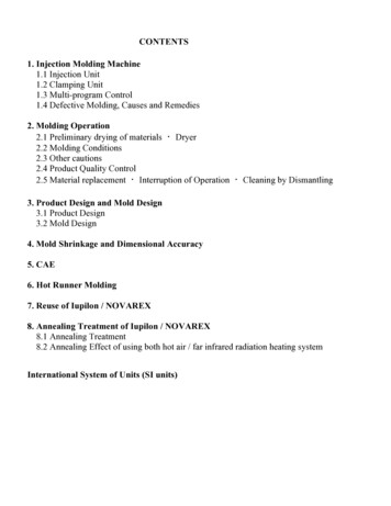
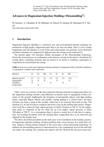
Metals 2016, 6, 1181182 of 12like powder pressing and sintering of Mg [4], powder forging or metal injection molding (MIM)powderpressingsintering of Mg [4], powder forging or metal injection molding (MIM) ofof Mg [5,6]can beandapplied.Mg [5,6] can be applied.MIM of Mg, in particular, seems to be very attractive since Mg alloys were identified as being aMIMof Mg,in particular,orthopedicseems to beimplantvery attractiveMg alloysapplicationswere identifiedas beinghighly suitablebiodegradablematerial sincefor shapebiomedicalapplicationsof[7–17].Mg alloyscan biodegradablebe used for theorthopedicindustrial implanteconomicnear netmass ��shaped implants at high reproducibility in large ilitylargeofnumbers.However, sinteringand,beyond that,inMIMMg is still not a standardized process. InHowever,sinteringsintering ofof MgMg hadand,beenbeyondthat, MIMMg is stillfornotmanya standardizedprocess.In thethe literature,reportedto beofunfeasibleyears becausethe nfeasibleformanyyearsbecausethestableoxide layer of Mg acts as diffusion barrier for the essential diffusion process during sinteringoxide[18].layerof Mg aactstheprocessduring sintering[18]. Thereafter,Thereafter,lot asof diffusionwork wasbarriercarriedforoutinessentialorder to diffusionunderstandthe sinteringperformanceof Mg andatolotof workthewasprocessingcarried outofinsinteringorder to understandsinteringperformanceMg and theto developdevelopMg [19–21].theThemain challengesof ineoxygen‐affine metal are the prevention of any additional oxygen pick up on the one hand and themetalare theof betweenany additionaloxygenpickup onortheone handand thepreventionofpreventionof preventionany reactionsMg andpolymerbinderthermaldebindingproductson ebindingproductsontheotherhand.other hand. In [19–21] small amounts of Ca could be highlighted as a considerable sintering aid byIn[19–21]a smallof Cacould be thehighlightedas liquidamountsphase andweakeningoxide layerthe Mg particles,andaidanbyadditionwt.phaseand weakeningthe oxidelayer ofMg particles,and an Therefore,addition ofin0.9thiswt.work% Ca anprovedto be% Ca provedto be optimalin termsof themechanicalproperties.Mg‐0.9Caoptimaltermsof mechanicalproperties.Therefore,this workan rheologicalMg-0.9Ca alloyis used.alloy is inused.Moreover,the polymerbindermust inprovidegoodbehaviortoMoreover,fulfil thethepolymer bindermust providegoodpartrheologicalbehaviorto thefulfilinjectionthe requirementsfor a Hence,failure freerequirementsfor a failurefree greenproductionduringmolding step.thegreenduring binderthe injectionmoldingisstep.Hence,thewillchoicesuitable polymerchoicepartof productionsuitable polymercomponentslimitedandbe ofdiscussedin this binderstudy.componentslimitedofandwill bediscussedin thisstudy.suchTherefore,the impactof severalorganicTherefore, theis impactseveralorganicpolymerbindersas polybuthene(PB),polypropylenepolymerbinders suchcopolymeras polybuthene(PB), (PP), polypropylenepolybutene(PPcoPB) illingquality(PPcoPE) on the mold filling quality during injection molding and on the sintering ability ofduringMg isinjectionmoldingthe sintering ability of Mg is within the scope of this study.within thescope ofandthisonstudy.MIM of Mg-0.9CaMg‐0.9Ca alloy was performed very successfully with different materials and testingspecimens. More complex demonstrator parts as shown in Figure 1a and biodegradable bone screwdemonstrators as shown in FigureFigure 1b1b couldcould bebe manufactured,manufactured, too.too.(a)(b)Figure 1.1. (a)Bookmark demonstratormetal injectioninjection moldingmolding (MIM)(MIM) ofof Mg-0.9CaMg‐0.9CaFigure(a) Bookmarkdemonstrator partsparts mademade byby ock at Helmholtz-Zentrum Geesthacht. The parts on the left are in the as sintered condition; eshrinkageofthesinteredpartsisveryparts on the right are the corresponding green parts. The shrinkage of the sintered parts is very clearlyclearly invisiblein comparisonto thesizeof thegreen(b)anchorSuturescrewsanchorproducedscrews producedbyvisiblecomparisonto the sizeof thegreenparts.(b)parts.Sutureby injectioninjection techniquemolding techniquesameLowerscrewshows a partsinteredpart producedmoldingusing theusingsame themold:(1)mold:Lower(1)screwshowsa sinteredproducedby lendattheHelmholtz‐ZentrumGeesthachtof Mg-0.9Ca feedstock from Mg-0.9Ca powder blend at the Helmholtz-Zentrum Geesthacht oly efromPLDLAL-lactide/DL-lactidecopolymer),using ourtesy:ConmedLinvatec.the MIM Mg-0.9Ca screw. Courtesy: Conmed Linvatec.Another aspect of MIM of Mg alloys is illustrated in Figure 1b. Recently, in clinical usage,Another aspect of MIM of Mg alloys is illustrated in Figure 1b. Recently, in clinical usage,biodegradable implants have been made of poly L‐lactide/DL‐lactide copolymers (PLDLA) whichbiodegradable implants have been made of poly L-lactide/DL-lactide copolymers (PLDLA) whichsuffer from low mechanical strength and stiffness as well as from acidulous degradation behaviorsuffer from low mechanical strength and stiffness as well as from acidulous degradation behavior (see(see Figure 1b, upper screw) and, thus, an increased inflammatory risk after implantation. These
Metals 2016, 6, 1183 of 12Figure 1b, upper screw) and, thus, an increased inflammatory risk after implantation. These PLDLAcopolymer screws are made by injection molding technique as well. Hence, the polymer based screwscan be substituted by MIM-Mg-based screws using the same injection molding technique and the samemold, as shown in Figure 1b.In this paper, an overview on the challenges and recent success of MIM of Mg is given, focusingon the role of binder on the sintering behavior.2. Materials and Methods2.1. Powder and Feedstock (or Feedstockpreparation)Pure spherical and commercially available gas atomized Mg-powder was used as base material(SFM, Martigny, Switzerland). A spherical gas atomized Mg-10Ca powder (ZfW, Clausthal, Germany)was used as master alloy powder (MAP) to prepare Mg-0.9Ca powder blends by mixing the twocomponents. Paraffin wax components, stearic acid and several organic polymer binder componentsas shown in Table 1 were used to prepare the feedstock for the injection molding process. Polymercontent was varied between 5 and 35 m. % of the binder system. The powder loading was 64 vol. % forall feedstock batches. The two powder components and the organic binder components were placedin a mixing cup, preheated up to 160 C and mixed in a planetary mixer by stirring the componentsfor five minutes applying maximum rotation speed of 2000 rpm (Thinky ARE 250 planetary mixer,Tokyo, Japan). The homogeneity of the batch was checked by stirring the feedstock with a spittle.The described process can be iterated until homogeneity of the feedstock is adequate. To avoid anyoxygen uptake of the magnesium powder components, the materials were handled in protective argonatmosphere in a glovebox system (Unilab, MBraun, Garching, Germany).Table 1. Used binder components for MIM of Mg.BinderAbbreviationManufacturerparaffin waxparaffin waxstearic acidpolypropylenepolybuthenepolypropylene copolymer polybutenepolypropylene copolymer polyethylenepolyethylene copolymer venylacetatePW 65PW 55StAPPPBPPcoPBPPcoPEPE-VAFisher ScientificMerckMerckSigma-Aldrich*Bassell* Manufacturer cannot be named due to proprietary interest.2.2. Metal Injection Moulding (MIM)Injection molding of the feedstock was carried out by using an industrial injection moldingmachine (320S Allrounder, Arburg, Loßburg, Germany). Rectangular test specimens (l 43.4 mm,w 5.4 mm, h 2.9 mm), cylindrical rods (d 4.5 mm, l 30 mm), dogbone-shape tensile test specimensconsistent to ISO 2740 and different demonstrator parts (bookmarks) as well as medical bone screwimplant demonstrators as shown in Figure 1a,b were manufactured.2.3. Debinding and SinteringChemical debinding of the paraffin wax components and the stearic acid was carried out in ahexane bath at 45 C for 10 to 15 h by using an automatic solvent debinding device (EBA50/2006,Lömi, Großostheim, Germany). Thermal debinding and sintering was performed in a combineddebinding and sintering hot wall tube furnace with integrated binder precipitation zone (XRetort,Xerion, Freiberg, Germany).
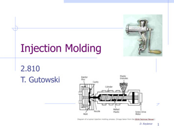
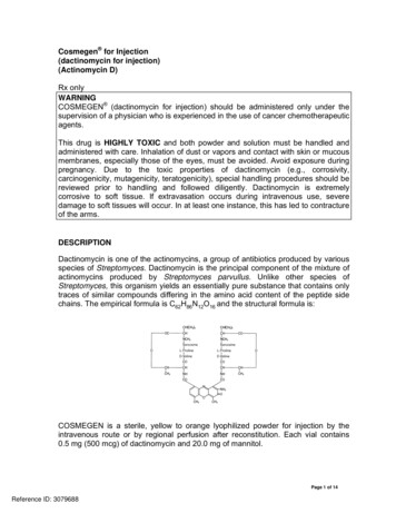
Metals 2016, 6, 1184 of 12MetalsThermal2016, 6, 118debindingwas performed according to the diagram in Figure 2. After having taken4 of 12several preparatory steps like furnace evacuation and purging, gas tube purging and leakage check, C at 800 mbar, using high purity argon (Ar 6.0)the furnacefurnace waswas quicklyquickly heatedheated upup toto 300300 Ctheat 800 mbar, using high purity argon (Ar 6.0) to enablefast warmingwarming ofof the specimen.specimen. TheThe thermalthermal debindingdebinding tooktook placeplace inin reactivereactive ArAr 5%5% HH22 (Arcal(Arcal 15,15,fastAir Liquide,Liquide, between1to800mbarpressure between 1 to 800 mbar at1 hatmaymayoccur.occur.SinceSinceMgMghashas thethe highest1atL/mingasgasflowto toreducereactivebinder C [22]), it cannot be sintered under 27vapor(231.5 CSintering underunder vacuumvacuum conditioncondition wouldwould resultresult inin evaporationevaporation ofof thethe materialmaterial andand relatedrelatedcondition. Sinteringthe coldercolder binderbinder precipitationprecipitation areaarea of thethe furnace.furnace. However,However, debindingdebinding underunder vacuumvacuumdeposition in theconditions isis essentialessential for obtaining satisfying residual‐freeresidual-free thermal debinding. Hence,Hence, thethe heatingconditions 1 1phase after thermal debindingmbar) upup tophasedebinding waswas performedperformed underunder vacuumvacuum conditioncondition ( 1( 1 ˆ 1010 mbar)sintering temperature,temperature, before switching to argon atmosphere for long-timeInvestigationssinteringlong‐time sintering. Investigationsconcerning the sintering time and temperature were performed in earlier works [4–6].concerningFigureFigure 2.2. SinteringSintering regimeregime ofof thethe magnesiummagnesium sinteringsintering processprocess forfor MIMMIM Mg‐0.9CaMg-0.9Ca parts.parts.Sintering was conducted for 64 h at 635 Cfurnace temperature in Ar 6.0 atmosphere. As eachSintering was conducted for 64 h at 635 C furnace temperature in Ar 6.0 atmosphere. As eachspherical Mg particle is leaguered by a thin oxide layer which strongly inhibits the diffusionspherical Mg particle is leaguered by a thin oxide layer which strongly inhibits the diffusion betweenbetween neighbored Mg‐particles, this long sintering time is required to destabilize the oxide layerneighbored Mg-particles, this long sintering time is required to destabilize the oxide layer [4].[4].2.4. Characterisation Methods2.4. Characterisation MethodsThe rectangular bars and cylindrical rods were used for the non-destructive measurement of theThe rectangular bars and cylindrical rods were used for the non‐destructive measurement ofdynamic elastic modulus Edyn. , applying resonance sonic spectroscopy according to EN-ISO 12680-1the dynamic elastic modulus Edyn., applying resonance sonic spectroscopy according to EN‐ISOand ASTM E1875-08 (RFDA, IMCE, Genk, Belgium). The residual porosity Px and the shrinkage12680‐1 and ASTM E1875‐08 (RFDA, IMCE, Genk, Belgium). The residual porosity Px and thesf of the sintered rectangular bars and cylinders were determined using the Archimedes methodshrinkage sf of the sintered rectangular bars and cylinders were determined using the Archimedes(Sartorius-LA230S, Sartorius, Göttingen, Germany) and geometrical data assessment (Mahr-16EX,method (Sartorius‐LA230S, Sartorius, Göttingen, Germany) and geometrical data assessmentcalliper, Mahr, Göttingen, Germany).(Mahr‐16EX, calliper, Mahr, Göttingen, Germany).Archimedes densityPx “ 1 Archimedes density(1)Px 1 theoretical density(1)theoretical densitysf “ 1 sintered lengthgreen lengthsinteredlength(2)s f 1 (2)The tensile tests of sintered MIM Mg-0.9Cadogbone-shapetest specimen were performedgreenlengthaccording to DIN EN ISO 6892-1:2009 B on a materials testing machine (RM100, Schenck Trebel,The tensiletests ofThesinteredMIM Mg‐0.9Cadogbone‐shapespecimen were performedDarmstadt,Germany).microstructurewas observedby ,SchenckTrebel,Yxylon, Hamburg, Germany) and a scanning electron microscopy (SEM) (Zeiss-DSM 962, observedbyusingmicro‐tomography(Y.Cougar,Germany and Phenom-Pro X, Phenom-World, Eindhoven, The Netherlands). For microstructuralYxylon,Germany)and a scanningelectronmicroscopy (SEM) (Zeiss‐DSM 962, Zeiss,analysis Hamburg,samples werecut, embedded,ground andpolished.Jena, Germany and Phenom‐Pro X, Phenom‐World, Eindhoven, The Netherlands). Formicrostructural analysis samples were cut, embedded, ground and polished.3. Results and Discussion
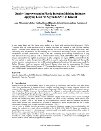
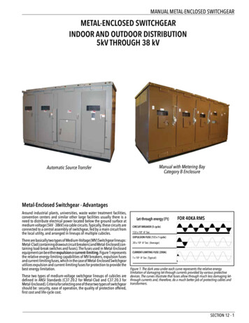
Metals 2016, 6, 1185 of 123. Results and DiscussionMetals 2016, 6, 1183.1. Young’sModulus vs. Residual Porosity RelationshipMetals 2016, 6, 1183.1. Young’s Modulus vs. Residual Porosity Relationship5 of 125 of 12Figure 3 shows the correlation between the Young’s modulus of the sintered MIM part and3.1. Young’svs. relationbetweenthe Young’sofmodulusof the modulussintered MIMpartandresidualitsits residualporosityPx .theThetypical lineardependencythe lFigure3 showswhichthe correlationbetweenintheYoung’s modulusof the sinteredpart andporosity isdisplayed,is often shownliteraturefor PM-materials[23].MIMHowever,theitslinearporosity porosityis displayed,whichis oftenshownin literatureforPM‐materials[23]. However,thelinearresidualPx. mtotalresidualtrend line fit shown in Figure 3 displays that the Young’s modulus will become zero when approachingtrend linefit shown whichin Figure3 displaysthe Young’smodulus [23].will However,become zerowhenporosityis displayed,is oftenshown inthatliteraturefor PM‐materialsthe linearapproximately40%of residual40%porosity.This istypicalThisfor sphericalPM-materialsbecause a typicalforsphericalPM‐materialstrend line fit shown in Figure 3 displays that the Young’s modulus will become zero whenporosityabove40% porositywould resultinno wouldcontactresultbetweenpowderparticlesand hence,zero andYoung’sbecausea totalabove40%in ximately40%of residualporosity.Thisis usingbecause a total porosity above 40% would result in no contact between the powder particles andto sin additionholdertechnique[24]or metalpowderfeedstockhence,zero gher porosityhas beenrenderedpossibleby ulustoresidualporosityofthesehighlyporousthe Young’smodulusto residualporosityof allyPM‐methodsin additionto spaceholdertechniqueor turesmay theoreticallyshow moduluszeroYoung’smoduluswhenapproachingof or ashowtechniquezero Young’smoduluswhenapproaching100%of residualporosityanda ofnear-polynomic-2nd[25].Thecorr
metals Article Metal Injection Molding (MIM) of Magnesium and Its Alloys Martin Wolff 1,*, Johannes G. Schaper 1, Marc René Suckert 2, Micha