Transcription
International Journal of Mechanical and Industrial TechnologyISSN 2348-7593 (Online)Vol. 4, Issue 2, pp: (72-79), Month: October 2016 - March 2017, Available at: www.researchpublish.comMinimization of Shrinkage in InjectionMolding Process of Acetal Polymer Gear UsingTaguchi DOE Optimization and ANOVAMethodRamkumar Ramakrishnan1, Dr. Ken Mao21PG student, 2Professor, University of Warwick, Coventry, EnglandAbstract: Injection molding is one of the very widely used manufacturing process for polymer materials due to itshigh production rate and low process cost. However, polymer parts manufactured through injection moldingprocess are prone to various defects such as geometrical defect, shape related defect and visual defects. Alldesigners work hard to minimize these defects and increase the quality of the molded part to satisfy the endapplication through the molding process parameters optimization with help of design of experiments (DOE). Themain objective of this paper is to study the effect of various injection molding process parameters on thevolumetric shrinkage of a acetal polymer gear part, identifying the most significant parameter causing highvolumetric shrinkage and optimizing the process parameters through Taguchi orthogonal array design andanalysis of variance (ANOVA) method. The acetal polymer gear injection molding process is simulated usingMoldflow adviser ultimate simulation software and the change in volumetric shrinkage is analysed for variousprocess parameters combination. Taguchi optimization and ANOVA method were found to be very useful indetermining the most significant molding process parameter that affect volumetric shrinkage and optimizing thecontrol parameters for achieving minimum part shrinkage.Keywords: Injection molding, polymer gears, shrinkage, Taguchi optimization, ANOVA method.1. INTRODUCTIONInjection molding is a well-established and well-developed manufacturing process used for the production of variousplastic parts ranging from simple to complex shapes. Thermoplastics such as low density polyethylene (LDPE), highdensity polyethylene (HDPE) and polypropylene (PP) are the very widely used polymer materials for the production ofhigh volume consumer goods [1]. High performance engineering thermoplastics such as acetal, nylon and PEEK are usedin various gear applications as an alternate material against metal gears. Polymer gears also offers various benefits overmetal gears such as weight reduction, noise reduction, torque reduction, reduced lubrication, etc [2]. Acetal also known aspolyoxymethylene is one of the very widely used high performance engineering thermoplastic. Acetal is known for itshigh tensile strength, high stiffness, high toughness, excellent chemical resistance, low friction, etc [3]. Shrinkage is oneof the major defect which occurs during the packing and cooling phase of the plastics injection molding process. Thegeometric reduction in the size of molded part is referred as shrinkage while the three dimensional reduction in thevolume of the molded part is known as volumetric shrinkage [4]. Shrinkage cannot be eliminated completely in theinjection molding process which is due to the fact that all polymers materials will undergo certain amount of contractionwhen it is cooled. However, shrinkage can be minimized by controlling and optimizing the injection molding processparameters such as melt temperature, mold temperature, packing time, packing pressure and cooling time [5].Page 72Research Publish Journals
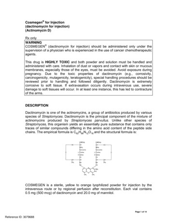
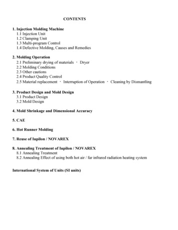
International Journal of Mechanical and Industrial TechnologyISSN 2348-7593 (Online)Vol. 4, Issue 2, pp: (72-79), Month: October 2016 - March 2017, Available at: www.researchpublish.comThe Taguchi method is one of the very widely used statistical tool for the optimization of molding process parameterswhich in turn help in minimizing the various process defects such as shrinkage, sink marks, warpage and high molded instress. Taguchi method DOE also allows the designer to choose the suitable array depending upon the number of controlfactors and their levels [6]. The signal to noise ratio which is called as S/N ratio in short is a very powerful qualityindicator in Taguchi method which evaluates any small change in the input parameters on the output variable [7].Tuncay and et al minimized the warpage and sink marks in injection molded thermoplastic material using Taguchioptimization and ANOVA method. They also found the most significant control parameter affecting warpage and sinkmark and optimised them with help of Taguchi DOE method [8]. Rishi Pareek and et al studied the effect of variousinjection molding process parameters on the tensile strength of a polycarbonate material. They also identified the melttemperature as the most significant control parameter for tensile strength and optimised the control parameters usingTaguchi orthogonal array design and ANOVA method [9]. Mathivanan and et al studied the effect of molding variableson sink mark depth of injection molded part and found that the rib distance from the feed point as the most significantfactor in minimizing the sink mark defect [10]. Nik Mizamzul and et al studied the effect of injection molding processparameters on two response variables including deflection and volumetric shrinkage of a polypropylene spur gear usinggrey relational analysis and ANOVA method [11].2. SCOPE OF STUDYThe scope of this study are as follows,1. The material chosen for this study is acetal (also called as polyoxymethylene) and the grade of material selected isDelrin 500P.2. The control factors chosen for this study are melt temperature, mold temperature, packing time, packing pressure andcooling time.3. The response variable chosen for this study is volumetric shrinkage4. The volumetric shrinkage is simulated using Moldflow Adviser Ultimate software, an Autodesk product and the DOEis run using Minitab 17 software.5. The deliverables of this study includes the identification of the most significant control factor and optimization of thecontrol factors for achieving minimum volumetric shrinkage.3. MATERIALThe polymer material selected for this experimental study is Delrin acetal 500P grade, a high performance engineeringpolymer manufactured by DuPont. The mechanical properties of Delrin acetal 500P and its recommended moldingconditions are as shown in the below tables [12]. The gear model selected for this work is 30 teeth 2 module spur gear asshown in figure 1.Figure 1: Spur gear model with 2 module and 30 teeth configurationPage 73Research Publish Journals
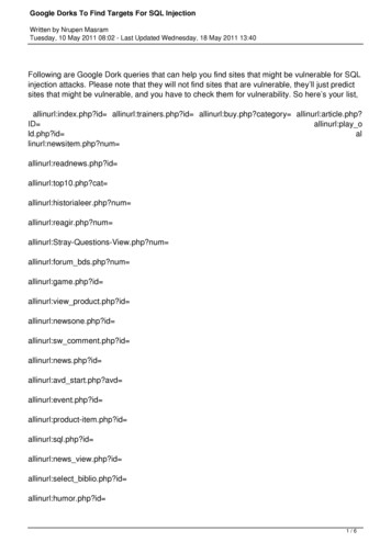
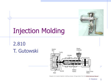
International Journal of Mechanical and Industrial TechnologyISSN 2348-7593 (Online)Vol. 4, Issue 2, pp: (72-79), Month: October 2016 - March 2017, Available at: www.researchpublish.comTable 1: Properties of Delrin acetal 500P grade polymerS. No.123456DescriptionDensityYield stressTensile modulusFlexural stressFlexural modulusStrain at break 0040Table 2: Recommended injection molding parameters for Delrin acetal 500P grade polymerS. No.12345DescriptionMelt temperatureMold temperatureHold pressureDrying temperatureMolding ue205 – 22580 – 10080 – 10080i)ii)1.92.0Mold Construction and Runner system design:Figure 2: Mold cavity and runner systemThe gating system selected for this study is radial type runner system with the tapered gate end acting as the injectionpoint on the top land of the gear teeth. Radial type gate is one of very commonly used gating system in the plasticsinjection molding process. The dimensions of the runner systems are shown in the below table. The mold materialselected for this study is P20 steel with A-Plate assembled on the stationary side of injection molding machine while BPlate is assembled to the moving side of the machine.Table 3: Gating system dimensionsRunner elementSprueElement typeTaperedRunnerColdGateTaperedElement dimensionsLength – 110 mmDiameter, D1 – 3 mmDiameter, D2 – 8 mmLength – 22 mmDiameter – 5 mmLength – 5mmDiameter, D1 – 5 mmDiameter, D2 – 1.5 mmPage 74Research Publish Journals
International Journal of Mechanical and Industrial TechnologyISSN 2348-7593 (Online)Vol. 4, Issue 2, pp: (72-79), Month: October 2016 - March 2017, Available at: www.researchpublish.comSelection of Control factors and levels:The control factors selected for this DOE are melt temperature (A), mold temperature (B), packing time (C), packingpressure (D) and cooling time (E). The upper and lower limit values for melt temperature, mold temperature and packingpressure are selected based on the recommended molding conditions for Delrin acetal 500P material grade. All the fivecontrol parameters are varied in five different levels and hence Taguchi L25 orthogonal array design is chosen for thisstatistical analysis.Table 4: Selected control factors and levelsControl FactorsLevels12345Melt temperature (⁰C)205210215220225Mold temperature (⁰C)80859095100Packing time (sec)1020304050Packing pressure (MPa)80859095100Cooling time (sec)5060708090Taguchi Orthogonal array design:The L25 orthogonal array design is selected considering the five control factors and their five levels.Table 5: Taguchi L25 Orthogonal array Control factorsMelttemperature (A)205205205205205210Moldtemperature (B)8085909510080Packingtime (C)102030405020Packingpressure (D)8085909510090Coolingtime 51008085708070809050225100409060Page 75Research Publish Journals
International Journal of Mechanical and Industrial TechnologyISSN 2348-7593 (Online)Vol. 4, Issue 2, pp: (72-79), Month: October 2016 - March 2017, Available at: www.researchpublish.comThe injection molding simulation is performed in the Moldflow adviser software for 25 runs as per table 5 and the valuesof volumetric shrinkage is noted as the response for which the signal to noise ratio (S/N ratios) is calculated. The type ofS/N ratio chosen for this study is “smaller the better” as the objective is to minimize the volumetric shrinkage.Table 6: S/N ratio for volumetric shrinkage as response 425Control eS/N 6602Figure 3: Main effects plot for SN ratiosPage 76Research Publish Journals
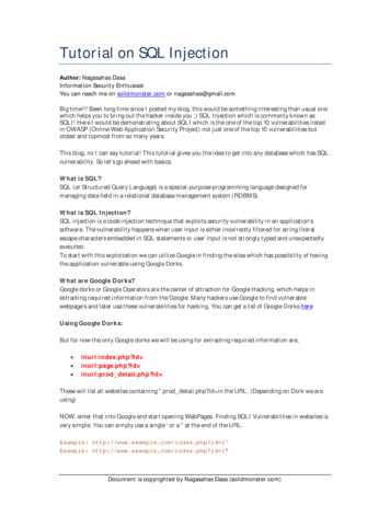
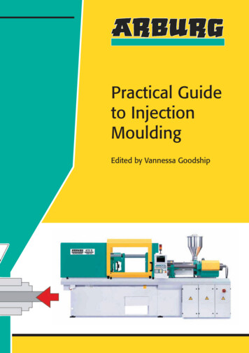
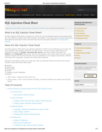
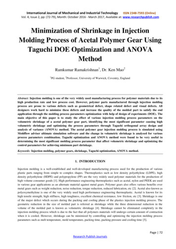
International Journal of Mechanical and Industrial TechnologyISSN 2348-7593 (Online)Vol. 4, Issue 2, pp: (72-79), Month: October 2016 - March 2017, Available at: www.researchpublish.comFrom the main effects plot for S/N ratios “smaller the better” as shown in figure 3 it can be determined the bestparameters combination for minimum volumetric shrinkage is A1-B5-C5-D5-E1 and similarly the worst parameterscombination that would result in maximum volumetric shrinkage is A5-B2-C1-D1-E4.Table 7: Validation run for volumetric Coolingtime5080Volumetricshrinkage17.5719.33Table 8: Taguchi DOE Vs Moldflow simulation result validationProcess parameters combinationMinimum volumetric shrinkageMaximum volumetric shrinkageDOE Prediction(using Minitab)17.5119.54Moldflow simulationprediction17.5719.33% Error margin0.341.07However, the best parameters combination for minimum volumetric shrinkage and worst parameters combination formaximum volumetric shrinkage are not included in the Taguchi L25 DOE array and hence validation run is performed forthose two combinations in the Minitab software and as well in the Moldflow adviser software. From the above validationrun in table 7 and 8, the optimum process parameters combination for achieving minimum volumetric shrinkage are melttemperature 205⁰C, mold temperature 100⁰C, packing time 50 sec, packing pressure 100 MPa and cooling time 50 sec.The minimum and maximum volumetric shrinkage prediction by Minitab software seems to be in line with the Moldflowadviser prediction with minimum error margin. This validates the effectiveness of using Taguchi DOE technique indetermining the optimum level of control factors for achieving minimum part shrinkage.Figure 4: Volumetric shrinkage with validation run 1Figure 5: Volumetric shrinkage with validation run 2The simulated volumetric shrinkage at ejection for validation parameters are shown in figure 4 and 5. It can be observedthat the minimum and maximum volumetric shrinkage of the simulated polymer gears are lower for the processparameters listed in validation run 1 which refers to the optimum parameters combination for achieving the lowervolumetric shrinkage. In case of simulation with parameters combination of validation run 1, the minimum shrinkage onteeth regions is 2.44% while the maximum shrinkage in between the teeth and hub regions is 17.57%. In case ofsimulation with parameters combination of validation run 2, the minimum shrinkage on teeth regions is 2.58% while themaximum shrinkage in between the teeth and hub regions is 19.33%. The volumetric shrinkage is lower by 1.76% in caseof validation run 1 as compared with validation run 2. This volumetric shrinkage comparison through validation runconfirms the optimum process parameters of melt temperature 205 ⁰C, mold temperature 100 ⁰C, packing time 50 sec,packing pressure 100 MPa and cooling time 50 sec as the best combination. Also the below response table for S/N ratiosPage 77Research Publish Journals
International Journal of Mechanical and Industrial TechnologyISSN 2348-7593 (Online)Vol. 4, Issue 2, pp: (72-79), Month: October 2016 - March 2017, Available at: www.researchpublish.comconfirms the melt temperature as the most significant process parameter with rank 1, followed by packing pressure as rank2, packing time as rank 3, cooling time as rank 4 and mold temperature as rank 5.Figure 6: Response table for S/N ratiosThe percentage contribution of each control parameter on the response variable (i.e.) volumetric shrinkage is calculatedusing the method of analysis of variance as per table 9 in which the f is degree of freedom, S is the sum of squares, V isthe value of variance, F is the F-ratio and P is the percentage contribution.Table 9: Analysis of variance for volumetric shrinkageControl FactorsfSVFP (%)Melt temperature46.906541.726640839.895.12%Mold temperature40.012020.0030101.460.17%Packing time40.077700.0194309.451.07%Packing pressure40.241700.06043029.393.33%Cooling Total247.260900.11%100.00%From the above ANOVA table, it was found that the most significant control parameter which affects volumetricshrinkage is the melt temperature contributing about 95.12% followed by packing pressure which contributes to 3.33%.The other parameters including packing time, mold temperature and cooling time were found to be insignificant and havevery negligible effect on the volumetric shrinkage.4. CONCLUSIONThe design of experiments through Taguchi orthogonal array and analysis of variance method found to be very useful indetermining the significant process parameter having the maximum effect on the response variable volumetric shrinkageand also helped in optimizing the control parameters for achieving minimum volumetric shrinkage. For acetal polymergear injection molding, the melt temperature is having the highest percentage contribution on the volumetric shrinkagefollowed by the packing pressure. For achieving minimum volumetric shrinkage, it is recommended to operate with thelower limit of melt temperature (i.e.) 205⁰C and upper limit of packing pressure (i.e.) 100 MPa.REFERENCES[1] V. Goodship, B. Middleton, and R. Cherrington, Design and Manufacture of Plastic Components forMultifunctionality. Elsevier Inc., 2011.[2] Victrex, It’s Time to Scrap Metal Gears. 2013.[3] S. Lüſtl, V. P.M, and S. Chandran, Polyoxymethylene Handbook. 2014.[4] Fisher, HANDBOOK OF MOLDED PART SHRINKAGE AND WARPAGE. 2013.Page 78Research Publish Journals
International Journal of Mechanical and Industrial TechnologyISSN 2348-7593 (Online)Vol. 4, Issue 2, pp: (72-79), Month: October 2016 - March 2017, Available at: www.researchpublish.com[5] P. C. Bolur, A guide to injection molding of plastics.[6] C. Shen, L. Wang, W. Cao, and L. Qian, “Investigation of the Effect of Molding Variables on Sink Marks of PlasticInjection Molded Parts Using Taguchi DOE Technique,” Polym. Plast. Technol. Eng., vol. 46, no. 3, pp. 219–225,2007.[7] M. M. Alam and D. Kumar, “Reducing Shrinkage in Plastic Injection Moulding using Taguchi Method in TataMagic Head Light,” Ijsr, vol. 2, no. 2, pp. 107–110, 2013.[8] T. Erzurumlu and B. Ozcelik, “Minimization of warpage and sink index in injection-molded thermoplastic partsusing Taguchi optimization method,” Mater. Des., vol. 27, no. 10, pp. 853–861, 2006.[9] R. Pareek and J. Bhamniya, “Optimization of Injection Moulding Process using Taguchi and ANOVA,” Int. J. Sci.Eng. Res., vol. 4, no. 1, pp. 1–6, 2013.[10] D. Mathivanan, M. Nouby, and R. Vidhya, “Minimization of sink mark defects in injection molding process –Taguchi approach,” Int. J. Eng. Sci. Technol., vol. 2, no. 2, pp. 13–22, 2010.[11] N. M. Mehat, S. Kamaruddin, A. R. Othman, A. Gomez, and J. Wei, “Modeling and Analysis of Injection MouldingProcess Parameters for Plastic Gear Industry Application,” ISRN Ind. Eng., vol. 2013, no. 10, 2013.[12] DuPont, “Delrin acetal resin molding guide,” 2006.Page 79Research Publish Journals
Table 2: Recommended injection molding parameters for Delrin acetal 500P grade polymer S. No. Description UOM Value 1 Melt temperature ⁰C 205 – 225 2 Mold temperature ⁰C 80 – 100 3 Hold pressure MPa 80 – 100 4 Drying te