Transcription
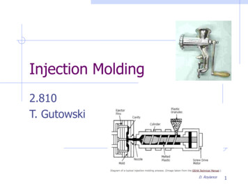
Injection Molding2.810T. GutowskiD. Roylance1
V-6 air intake manifoldWater control valveBrass Vs injection moldwww.mnrubber.com2
Short history of eflonNylon stockingsvelcro“The Graduate”Earth Day recycling3
Ref Kalpakjian and SchmidMcCrum, Buckley, Bucknall 4
OutlineBasic operationCycle time and heat transferFlow and solidificationPart designToolingNew developmentsEnvironment5
30 ton, 1.5 fl oz (45 cm3) EngelInjection Molding Machinefor wheel fabrication6
Process & machine schematics**Schematic of thermoplastic Injection molding machine* Source: ction process.htm7
Process OperationTemperature: barrel zones, tool, die zonePressures: injection max, holdTimes: injection, hold, tool openingShot size: screw travelProcessing ssure8
Typical pressure/temperature cycle**Time(sec)Time(sec)Cooling time generally dominates cycle time* Source: http://islnotes.cps.msu.edu/trp/inj/inj time.html9
Calculate clamp force, & shot sizeF P X A 420 tons3.8 lbs 2245 cm3 75 ozActual ; 2 cavity 800 ton10
Clamp force and machine costBoothroyd/Busch11
Heat transferNote; aTool apolymer1-dimensional heat conduction equation :qxqx DqxFourier’s lawBoundary Conditions:The boundary condition of 1st kind applies to injection molding since thetool is often maintained at a constant temperature12
Heat transferTiitLet Lch H/2 (half thickness) L ; tch L2/a ;DTch Ti – TW (initial temp. – wall temp.)TW-LxNon-dimensionalize: LDimensionless equation:Initial conditionBoundary conditionSeparation of variables ;matching B.C.; matching I.C.13
Temperature in a slabCenterline, q 0.1, Fo at/L2 1See Heat Transfer TextBy Lienhard on lineBi-1 k/hL14
Reynolds NumberReynolds Number:For typical injection moldingFor Die casting* Source: ction process.htm15
Viscous Shearing of FluidsFvF/Amh1v/hNewtonian ViscosityGeneralization:Injection molding“Shear Thinning” 1 sec-1 for PETypical shear rate forPolymer processes (sec)-1ExtrusionCalenderingInjection moldingComp. Molding102 10310 102103 1041 1016
Viscous HeatingRate of Heating Rate of Viscous WorkRate of Temperature riseRate of Conduction outBrinkman numberFor injection molding, order of magnitude 0.1 to 1017
Non-Isothermal FlowFlow rate: 1/t V/LxvPéclet No.Heat transfer rate: 1/t a/(Lz/2)2Small value Short shotFor injection moldingFor Die casting of aluminum* Very small, therefore it requires thick runners18
Non-Isothermal FlowFlow rate: 1/t V/LxvPéclet No.Heat transfer rate: 1/t a/(Lz/2)2Small value Short shotFor injection moldingFor Die casting of aluminumVery small value for aluminum requires thicker runners19
Injection molddie cast mold20
Fountain Flow**** Source: http://islnotes.cps.msu.edu/trp/inj/flw froz.html ; ** Z. Tadmore and C. Gogos, “Principles of Polymer Processing”21
Shrinkage distributionssampleTransverse directionV 3.5cm/sV 8cm/s* Source: G. Menges and W. Wubken, “Influence of processing conditions on Molecular Orientation in Injection Molds”22
Gate Location and WarpingSprue2.060 2.0Before shrinkage1.96ShrinkageDirection of flow – 0.020 in/inPerpendicular to flow – 0.01260.32 1.976After shrinkageAir entrapmentGateCenter gate: radial flow – severe distortionDiagonal gate: radial flow – twistingEdge gate: warp free, air entrapmentEnd gates: linear flow – minimum warping23
Effects of mold temperature andpressure on shrinkageLDPELDPE0.030PP0.025Acetal0.0250.020Nylon alPP withflowPP 0100120140160180200Mold Temperature (F)220240600010000800014000120001800016000Pressure on injection plunger (psi)24
Where would you gate this part?25
Design Features*** Source: ction design 2.htm26
Weld line, Sink markGateWeld lineMold FillingSolidified partSink mark* Source: ction design 7.htmBasic rules in designing ribsto minimize sink marks27
28
Where is injectionmolding?Controlled by shrinkageand warping. Hence,polymer, fillers, moldgeometry and processingconditions can allinfluence the finaltolerance.Shrinkage is of order10-100/1000 for unfilledand1-10/1000 for filled acrossthe thickness29
Where is injectionmolding?Controlled by shrinkageand warping. Hence,polymer, fillers, moldgeometry and processingconditionsFrom Boothroydet al can allinfluence the finaltolerance.Shrinkage is of order10-100/1000 for unfilledand1-10/1000 for filled acrossthe thickness30
Tooling BasicsSprueNozzleCore PlateCavity PlateMouldingCoreCavityCavityGateBasic mould consisting of cavity and core plateRunnerMelt Delivery31
Tooling for a plastic cupNozzleKnobRunnerCavityPartStripper plateCore32
Tooling for a plastic ityPartPartStripperplate33
partSide pullSide pull in positionToy tooling examplefrom Protomold34
Tooling********35* Source: http://www.idsa-mp.org/proc/plastic/injection/; ** http://www.hzs.co.jp/english/products/e trainer/mold/basic/basic.htm (E-trainer by HZS Co.,Ltd.)
Tooling AlternativesKalpakjian & Schmid36
Injection Molding HomeworkUndercut features to hold tape onEvidence of toolingfeature37
Part design rulesSimple shapes to reduce tooling cost No undercuts, etc.Draft angle to remove part In some cases, small angles (1/4 ) will doProblem for gearsEven wall thicknessMinimum wall thickness 0.025 inAvoid sharp cornersHide weld lines Holes may be molded 2/3 of the way through thewall only, with final drilling to eliminate weld lines38
Novel development- Gasassisted injection molding39
Novel development ; injectionmolding with coresInjection Molded HousingCores used in Injection MoldingCores andPart Molded in Clear Plastic40
Micro injection molding41
Conformal Cooling ChannelsTooling built usingAdditive ManufacturingInnomis.cz42
Environmental issuesEnergy Polymer production Compounding Machine typesRecycling43
44
Polymer ProductionLargest Player in the Injection Molding LCIWhat is a polymer:How much energy does it take to make 1 kg of polymer a lot !!!Values are in MJ per kg of polymer produced. Thiriez 45‘06
Gold 250 GJ/kgAshby 200946
Compounding - extrusionAn extruder is used to mix additives with a polymer base, tobestow the polymer with the required characteristics.Similar to an injection molding machine, but without a moldand continuous production.Thus it has a similar energy consumption profile.Environmentally Unfriendly Additives: Fluorinated blowing agents (GHG’s) Phalates (some toxic to humanliver, kidney and testicles) Organotin stabilizers (toxic anddamage marine wildlife)47
Injection Molding br-hylectric03a.pdfMachine types: Hydraulic, electric, hydro-electric48
All-electric vs. hybridSource: [Thiriez]The hydraulic plot would be even higher than the hybrid curve49
For Hydraulics and Hybrids as throughputincreases, SEC k.Does not account for the electric grid.Source: [Thiriez]Enthalpy value to melt plastics is just 0.1 to 0.7 MJ/kg !!!50
All-electrics have very low fixed energy costs (smallidling power). SEC is constant as throughputincreases.51Source: [Thiriez]
DriersUsed to dry internal moisture in hygroscopic polymers and externalmoisture in non-hygroscopic ones.It is done before extruding and injection molding.Source: [Thiriez]Same as52
LCI Summarized Results53
Source: [Thiriez]54
55
Do Polymers get recycled?Ref Ashby 200956
The printer goes in the hopper 57
And comes out .58
Readings (first 3) & RefsTadmore and Gogos Molding and Casting pp 584 -610Boothroyd Dewhurst Design for Injection Molding pp 319 - 359Kalpakjian Ch 7 & 19Thiriez et al, "An Environmental Analysis of InjectionMolding“"Injection Molding Case Study“ (Gas Assist)59
Compounding - extrusion An extruder is used to mix additives with a polymer base, to bestow the polymer with the required characteristics. Similar to an injection molding machine, but without a mold