Transcription
The Villages Antenna GuidePresented to The Villages Amateur Radio Clubon September 18th, 2007Edited by Ed Crowell, W5TWRCopyright 2008 by Edwin Crowell, W5TWR and The VillagesAmateur Radio Club, The Villages, FL 32162 — All rights reserved
TABLE OF CONTENTSAcknowledgements . 3Background of PRB-1 . 4“Random” Length Long Wire Antennas . 6Flagpole Antennas . 14NVIS Dipole Antennas . 23Screwdriver Type Antennas. 30Full-Sized Trap Vertical Antennas. 32In-Door Beam Antenna . 36Small Loop Antennas . 37Double Helical-Coil Dipole Antennas . 40Full-Wave Loop Antennas . 4480/40 Attic Antenna . 52Bibliography and Web Sites . 59Internet Resources . 60Nothing Succeeds Like Success . 61Page 2
ACKNOWLEDGEMENTSThe Editor would like to thank the members of The Villages Amateur Radio Club for their cooperation and participation in the AntennaSeminar held on September 18th. Without their help this documentwould not have been possible.The tape recording of the discussion during the Antenna Seminarwas used as a basis for the text portion of what follows. This manuscript was transcribed, edited, and refined by the Editor and his collaborators. It forms the basis for this document.I also want to give special credit to the members who providedphotos of their installations for the visual part of this paper. The photos are clear record of what these installations look like and providevaluable information about how to proceed with antenna constructionand installation.Thank You!Page 3
PRB-1 Historical Background(Editorial Comment)At the time of this writing, the legal situation of amateur antennainstallation is very much in a quandary On the one hand, our CCR'srestrict outside antenna installations in The Villages. While FederalLaw pre-empts local law with regard to satellite dishes (absolute requirement not to prohibit), the amateur finds no support of a practicalnature while erecting antennas because of the ambiguity of the FederalPRB-1 legislation (which requires that states “must make reasonableaccommodation”). You may read Florida’s PRB-1 at: http://www.leg.state.fl.us/statutes/index.cfm?pp mode Display Statute&Search String &URL Ch0125/SEC561.HTMand p mode Display Statute&Search String &URL Ch0166/SEC0435.HTM&Title Note: If you are connected to the Internet you may access URL’s by right clickingon blue web links then selecting “Open Weblink in Browser”(Continued on page 5)Page 4
(Continued from page 4)Attempts of the Florida legislature to pass an effective version ofPRB-1 have languished in committee because of political issues. Efforts of Rudy Hubbard, the ARRL NFL Section Manager to get thislegislation moving have so far failed. Meanwhile the legal professionhas continued to write CCR's and ordinances for developers and citycouncils. In this atmosphere of unsettled law, we hams leap to rescuethe stressed-out citizens of this country who have suffered acts ofwar, natural disasters, and threats to life, limb and property. The victims of this legal morass are not the hams but our friends andneighbors! We only seek to mitigate the problems of our friends andneighbors by using our communications skills effectively. Let ushope that the FCC and the government can bury the hatchet and resolve the issues. Twenty-five states, as of this writing, have passed aversion of PRB-1.See l.Page 5
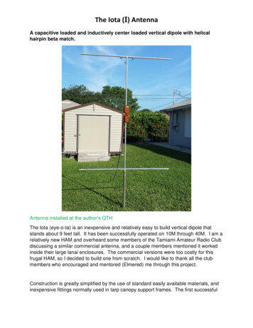
“Random” Length Long WiresThe antenna we discuss next is a longwire for80 and 40 meters as described by Andy Cebik,W4RNL (www.cebik.com/wire/lw2.html). Furthercomments regarding the advisability of using atruly “random” length of wire are provided by PatLambert, W0IPL (www.w0ipl.net). The wire lies directly on the roof of the house. I think you willagree it is a stealthy antenna.He also shows us how he tunes his two-band longwire.Page 6
Long Wire AntennasLook at the long wire antenna on theroof. It runs up the front of the roofon the left as you face the house, thenruns across the roof along the ridgevent (plastic construction), then downthe back of the roof to the eaves at anangle. The total length of the wire is88 feet.Page 7
Our Ham has hidden his antenna byplacing it under the shingles, andalong the ridge vent. The picturesshown here are mute testimony to thetechnique. He uses insulated wire andwhere he runs it under the shingles,takes advantage of the shingle adhesive (at the bottom edge of each shingle) to hold the wire in place.Page 8
The wire from the roof drapes overthe eave to an electric fence insulator seen here as yellow, then itgoes down the side of the house toa hole in the siding where it entersthe house shown on the next page.Elsewhere, he uses electric fenceinsulators, as shown above, easilyobtainable at farm supply storessuch as TSC, Menards, Lowe's,Home Depot, or Fleet Farm to secure the wire and hold it off thesiding. (another idea to which weshall return).Page 9
The Counterpoise WireThe wire from the roof runs intothe house on the right side ofthe hole. The left wire extending from the wall goes to twoground rods driven about fivefeet apart and also to a counterpoise wire that runs in theflower beds forward along theside of the house, then acrossthe front of the house to thedriveway and then along thedriveway to almost the street(again almost 88 feet). Thewires run into the house to bulldog clamps which attach thewires to the auto tuner (a common theme as you will see).Page 10
There is no transmission line! The wire is run as a single ended long-wire antennawhich is tuned against the counterpoise and two ground rouds. The length of the antenna and counterpoise are critical. It is certainly NOT random! More on this later!Page 11
He disconnects the bulldog clamps from the antennatuner and shorts them together to bring the antenna toground potential whenever a storm is near. He wantsno part of lightning when it is around. One of ournumber points out, lightning either goes down yourground wire or comes up it! Either way, it's not good!Page 12
Length of Long WiresOne has a choice of many lengths such as 63 feet,74 feet, 89 feet, or 111.5 feet. These numbers areobtained from calculations performed by PatLambert, W0IPL, and can be found on his website at: www.w0ipl.net/random-l.htm. Pat Lambert used to be Section Manager of the ColoradoSection. He has done a lot of writing about antennas, emergency management, communica tions, ARES Training and NVIS Propagation.Please check his site.Page 13
Various Flag Pole InstallationsMany people have used this antenna. They almost universallyfind that the work installing it is worthwhile. Most have useda choke balun, but have placed it at the shack instead of at theantenna. Some have used the standard 4 radials, some usedmore. Extensions to 20 or 24 feet have been tried with or without the loading coil. All but one have had trouble using it below 20. He has an auto tuner at the base of the antenna andhas a logbook (see Appendix) to prove his success. Landscaping around the base of the antenna is to be recommended foraesthetic reasons, and to please the XYL. To bury the radials,we suggest using an electric edging tool with a metal cuttingblade. Merely divide the sod with it and tuck the wire into thesod. The grass grows over it nicely.Page 14
The appearance has also been enhanced by placing it at the back ofthe lot in the flower beds like this ham has done. This configurationhas required 6 radials to be run in a 180 degree pattern resulting in a directive pattern to the northwest from his location (which is not all thatbad if you are in Florida).Page 15
How about adding rock and edging to dressup the base of a flagpole antenna?Page 16
This installation has aflagpole antenna set in a“well” surrounded withflowers. The “well” islined with brick and hasthe mounting for thepole and an auto tunerwrapped in a trash bag(tuner is waterproof).The “well” is filled withpea gravel for drainage,covered with lava rockand surrounded withflowers. This is what itlooks like—look hardthrough the flowers andsee if you can make itout?Page 17
Page 18
Page 19
Page 20
Page 21
A five inch diameter 8 turn choke balun isused to keep RF out of the shack. Others eschew the choke and say they have had noproblems without it. The best location for thechoke remains in doubt. One flag pole manufacturer says put it at the house so the coaxcan couple to the ground as a radial. ARRLHandbook says it works best at the antenna ifyou are using it for RF isolation. (Editor).Page 22
NEAR VERTICAL INCIDENCE SKYWAVE(NVIS) DIPOLESLook at the following backyard antenna setup. Hehas parallel dipoles for 80 and forty meters fed with600 ohm twinlead, and a coax lead-in. They are supported by PVC pipe with “T” connectors at the topfashioned around his fenceline. The lead-in goes under the window sash into the shack. He also shows ushis 2 meter ground plane antenna mounted on PVC,too. He uses cotton batting to close the space at thewindow closure.For a discussion of NVIS, see www.w0ipl.net. NVISmode is the subject of another whole paper!Page 23
This ham lives in a courtyard villa. He operates mainly on 80 and 40 meters. Hehas two runs of coax which go out the window of the bedroom, one to the HF antenna and the other to the 2 meter ground plane.Page 24
The antennas run at 5 and six feet respectively through PVC "T" connectors alongthe back fence to the opposite corners where they make a 90 degree turn forward(on each side). They come down to 5 feet on PVC pipes with "T" connectors at thelevel to serve as feed-thrus for the antenna wires. The "T" pipes are merely leanedagainst the wall where the bottom end is stuck in the ground.Page 25
Here he has two doublet antennas, one cut for 40 and one cut for 80.The center insulators are both at the same place. He merely screwsthe coax into whichever antenna he wants to use. The other is disconnected.Alternatively, one could connect the two antennas together like a bowtie antenna and leave them in parallel. There will be some interactionbetween the antennas, but that is not insurmountable. (Editor)Page 26
At present the forty meter antenna is attached to the PVC pole but if you are doing itagain, it is easy enough to put a second "X" connector a foot below the top one. Theantennas run forward until they end in a final insulator.Page 27
Page 28
His two meter antenna which is aground plane he got from a commercial vendor for 8. He mounted it ona five foot piece of PVC and simplystuck in the ground by the windowEven at this low level he can hit allthe repeaters and participate in twometer nets.Page 29
SCREWDRIVER ANTENNASThis ham is using a tunable mobile screwdriver antenna mounted on a portable tripod. Tuning is accomplished manuallywith a simple switch or by using an automatic memory tuner which will resetquickly once a previous frequency is accessed (computer). He has ground radialsstrung out in his back yard. The location ofthe antenna is in the back yard of his villawith the vertical element extending into anoak tree. As you can see, it is very hard topick it out of this background. When hewants to mow, he rolls up the radials, disconnects the coax and takes it into hishome’s lanai. He has this antenna in hisbackyard out by a large oak tree. Note thecoax leaving on the right side of the tripodunder the tree limbs. Landscaping stapleshold the radials in place. The coax is runthrough a hole in the wall from the front of(Continued on page 31)Page 30
the house under the lip of the vinyl siding to the downspout and then suspended from the downspout across to thetripod (just visible just to the right of the House). The whip on top of the coil merely goes up in the tree where it cannot be seen (picture).Page 31
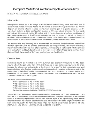
FULL-SIZED TRAP VERTICALSHere we have a trap vertical antenna. Thisone is not a flag pole type but QST has hadan article with this antenna hidden in ashroud made of PVC pipe* with a pulley andflag attached. He chooses to raise andlower his antenna. He uses a commercialfolding mounting product for the mount aswell as the radial attachment ring. *See reference to QST, May 1993.Page 32
This mount works with several manufacturer’s verticals.Basically it is a strong plate mounted on a pipe set in concrete or packed dirt. The plate is vertical and has "tracks"cut into it that guide the antenna up and down as it foldsto 90 degrees as it comes down. In use, it latches the antenna in the straight-up position for operating.*See Albert Parker in BibiographyDetails of FullSized VerticalPage 33
He has a quick disconnect device atthe base so he can remove the coaxfor mowing and a "fork" in theground where the antenna comesdown to support it until its next use.He has a thin-wall PVC pipe that willfit right over the vertical antenna andmake it look just like a flag-pole Antenna. He has forty insulated greenradials cut for twenty meters because of the size of his lot, but it stillworks great on the other bands, too.Verticals mounted above groundlevel require resonant radials attached to the base of the radiator.Ground mounted verticals do not.Radials in this case merely couple tothe ground. One needs to useenough of them long enough to effectively couple in your quality ofsoil. You can then let it down duringdaytime so the neighbors can't seeit! If you prefer, you can even permanently “lock” the antenna straightPage 34
up by using the “U” bolts at the topto tighten to the plate! The radialring allows an easy attachment ofthe radials at the base of the antenna where the ground point isconnected. When he mows or hasvisitors, he takes the forty radialsoff, disconnects the coax, andpulls the "U" bolts of the base pipeand puts the antenna and wires inthe bushes. This operator says healso uses a commercial two meterantenna mounted on a broom stickin the attic.Page 35
INDOOR BEAM ANTENNASThis ham has also used part of his beam antenna by putting it inthe attic. He had a tri-band beam with a forty meter trap for thedriven element, so he took the driven element and placed it in theattic, supporting the ends and the middle so it didn't droop toomuch. He worked a lot of DX on it without rotating it! I met a hamwho was doing the same thing. He had just moved to The Villagesand invited me over to see him. He showed me where he had put atri-band beam driven element into the attic (but of course, couldn'tturn it). He was going to give it a try just like the other ham. Several companies make rotatable dipoles similar tri-band driven elements for use on 80, 40, and 20 meters.Page 36
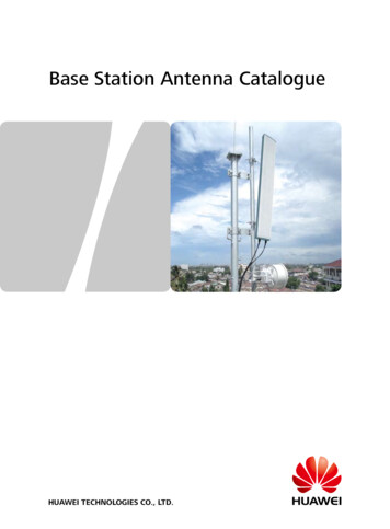
SMALL LOOP ANTENNASThis antenna will cover 30 meters up to 10 meters. It is 3 feet square and can be used in either the vertical or horizontal mode by loosening the "U" bolts on the rim of the loop and mounting the mast to thecenter mounting bracket. Then just flip the loop to horizontal and tighten. Several companies havemake small loops for 20 to 10 meters inclusive because they are all continuously tunable. Several articles in QST have shown how these loop antennas can be home-made. This loop would easily fit inyour attic even in a villa with virtually no attic. They can be tuned manually like the screwdriver antenna or can be tuned with a computer which will remember the settings (again like the screwdriver).Page 37
SMALL LOOP FEATURES cont.These antennas are easily portable and/or can be tilted down at night, The picture showsan example of this type antenna. They need to be high and so are a problem unless youwait until night to tilt them up. They do work, but not as well as a full sized antenna. Oneword of caution however, because they are very Hi-Q resonant they generate high voltagewhen transmitting. You or your friends can get a nasty RF burn from them so be carefularound them when energized!Refer to the picture on the next page:Looking at the antenna on the ground, one can see the coax connections to the one turnlink near the bottom. In addition to the coax, these antennas require a control cable to allow tuning of the large capacitor in the black box. This arrangement allows the antenna tobe used on continuous frequencies from low to high (CAP, Mars, and 60 meters could becovered by and adequately designed loop like this). Note the four silver rivets in the middle of the black box, these are for the tuning cable plug.Page 38
SMALL LOOP CONNECTIONSPage 39
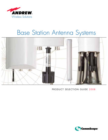
Double Helical DipoleThe following is from QST Issues May 2003, and Jan 2005 articles:The second antenna uses two helical wound whips. They can be home-made as was shown the QST inMay, 2003 (ref.) These are emergency communications antennas par-excellence. They can be mountedon a mast, tripod, or staked to the ground. In fact, a pair of forty meter helical wound whips can bemounted at right angles to a pair of 80 meter helical wound whips and fed with a single coaxial cable.They need to be tuned and are very sharp! The whips on each band need to be tuned to the same fre-Page 40
MOUNTED DOUBLE HAMSTICKquency and you can't QSY far without an antenna tuner. Don't forget to mark the stinger where thetuning is correct so you can reproduce the settings when you reassemble it later. This ham has usedthese very successfully with 65 watts on HF Packet mounted on the edge of the roof at an elevation ofonly 12 feet to contact Shreveport, LA. It takes five minutes to set up this antenna so one can go outon an emergency operations and be on the air in a jiffy! You can see that this antenna would fit in yourattic easily or on your back roof or along the fence of your yard. If you buy all the parts brand new,you will spend about 100 excluding the ground mount for the pole.Page 41
DETAIL OF HELICAL WHIP MOUNTPage 42
HELICAL WHIPMAST ATTACHED TOROOF OVERHANGPage 43
Full Wave Loop AntennasThe third antenna we have to show you is a full-wave Loop. Thisantenna has some interesting qualities. You cut it to frequency(1007/ F mhz) and arrange it in the general shape of a circle to asquare. It is resonant at the frequency for which it is cut. Thismeans it is about a quarter wavelength on a side. More than fourPage 44
ADVANTAGES/ DISADVANTAGESsupports begins to tax the ingenuity. The delta loop is avariety of this genre. However, it loads up on every harmonic (not just the odd multiples like most antennas). Itsfeed point impedance is 100 ohms. It can be fed directlywith your favorite coax, or you can use parallel feeders oreven twin lead. For perfection, one may use a quarterwave “Q” section of RG-11 (75 ohms) to transform the 100ohms down to 52, but then it would not be multi-band. Itsradiation pattern is straight up like a flattened beach ball.It is an NVIS antenna without peer. (for 3955 khz the RG11 would be 39 feet.) Even though you can hear everybody on the band which makes it a very good listeningantenna, you are unlikely to talk to anyone beyond thePage 45
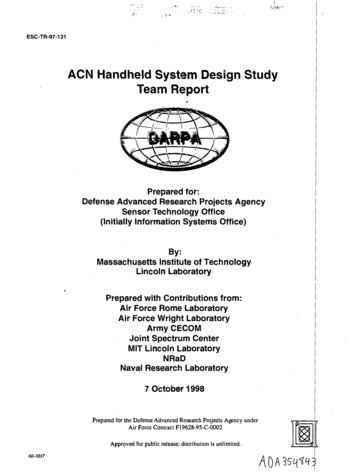
LOOP CORNER AT THE FIBERGLASSMASTadjoining states because it has virtually no low angle radiatedpower. However, you can talk to everyone within 400 miles even inthe skip zone. It is really cheap to build! If you tune it at the feed-Page 46
LOOP SECURED TO RIDGEVENTpoint with a wideband autotuner, it tunes all harmonically related bands (3.5,7.0, 10.5, 14, 17.5, 21, you getthe drill!) assuming it is cut forPage 47
INSULATOR AT ACORNER80 meters. This is known as theCloud Burner Antenna. The disadvantages of the antenna are theplethora of supports, need forenough real estate, and the ab-Page 48
AUTOTUNER ONTHE ROOFsence of skip propagation. But foremergency communications, statewide NTS work, and rag-chewing inthe region, you can't beat it!Page 49
ENTRY THROUGH THE WINDOW(THE YELLOW IS A STYROFOAMNOODLE)Page 50
ANDY CEBIK'S COMMENTSAndy prepared a program on the five best back-yard antennas forthe FDIM QRP Group at the Dayton Hamfest in 2004. He describes and summarizes his feelings about the full-wave Loopstarting on page 13 of his article located at:www.cebik.com/fdim/edim9.pdfIf you refer to this article and have room on your roof to buildone, you should find it a most useful stealth antenna.Page 51
80/40 Attic* AntennaThe final antenna is the 88 foot attic dipole tuned at the center with an auto tuner. This auto tuner is a wide-range typetuner unlike those found built into your rig back in the shack.Internal antenna tuners are made to tune a resonant antenna(beam or trap vertical) while you move around on the Bandbeyond the design center of the beam.Manual tuners and wide-band auto tuners will tune almostanything except an endfed wire one-half wavelength long atthe operating frequency (see W0IPL). The 52 ohm coax is flatall the way to the transmitter. The low pass filter works nicelyin the line as a further protection against interference in TheVillage (which would be the kiss of death).*For other attic antennas see Kai Siwiak in QST October2007 (in Bibliography).(Continued on page 53)Page 52
(Continued from page 52)Andrew Cebik, W4RNL, also has an extensive site at:www.cebik.comdedicated to antennas, their evaluation and recommendations. One of his practical suggestions has been for an antenna to use as a back-up for 80 and 40 meter operations only.He comes to the conclusion that a wire doublet antenna 88feet long is close to the best if you can only have one antenna. A bowtie antenna for 80 and 40 meters would be 128feet for 80 in parallel with a 59 foot dipole for 40 meters. Thisantenna is 40 feet shorter and still is tunable on both Bands.Page 53
THE AUTOTUNER IN THE ATTICPage 54
The ceramic insulators attached to the truss. Noteuse of nylon cable ties tosecure the wire.Page 55
Antenna turning the cornerat insulatorPage 56
The end insulator andtie-off pointPage 57
Make the Legs Fit Shape of AtticThe trick is to get the antenna to fit my attic. One can usestand-off insulators (either electric fence type or ceramic--seepictures). The antenna is then started in the center of thehouse where the antenna tuner is bolted to the trusses(picture). Each limb runs straight as far as it can, and then isbent 90 degrees to the garage on one end, and to the bedroomon the other. It is always better to bend the antenna only 90degrees rather than make a true “Z” out of it.P.S. Read “Attic Antennas” in QST for October 2007! He makesmany interesting points including RF Safety when using indoor(attic) antennas. A very good article. Also refer to “Table 4”for information regarding RF safety at:www.arrl.org/news/rfsafety/evalPage 58
BIBLIOGRAPHY1. A Disguised Flagpole Antenna, Albert Parker,N4AQ, QST, May 1973, p. 65.2. An All-Band Attic Antenna, Kai Siwiak,KE4PT, QST, October 2007, pp. 33-37.3. A Small, Portable Dipole for Field Use, RonHerring, W7HD, QST, May 2003, pp. 33-39.4. A Portable NVIS Antenna, Robert Hollister,N7INK, QST, January 2005, pp. 56-58.5. “Honey I Shrunk the Antenna”, Rod Newkirk,W9BRD, QST, July 1993, pp. 34-39.Page 59
INTERNET .cebik.com/fdim/fdim9.pdfAlso try following the hyperlinks in these sites for much moreinfo.Page 60
The antennas run at 5 and six feet respect ively through PVC "T" connectors along the back fence to the opposite corners wh ere they make a 90 degree turn forward (on each side). They come down to 5 feet on PVC pipes with "T" connectors at the level to serve as feed-thr