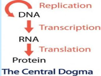
Transcription
Supporting InformationA DNA-Directed Light-Harvesting/Reaction Center SystemPalash K. Dutta,1,2 Symon Levenberg,1,2 Andrey Loskutov,2 Daniel Jun,3 Rafael Saer,3 J. ThomasBeatty,3 Su Lin,1,2 Yan Liu,1,2 Neal W. Woodbury,*,1,2 Hao Yan*,1,21Department of Chemistry and Biochemistry and 2The Biodesign InstituteArizona State University, Tempe, Arizona 85287, United States3Department of Microbiology and Immunology, University of British Columbia, Vancouver,British Columbia, V6T 1Z3, CanadaMethods and experimental detailsFigures S1-S12Tables S1-S3Schemes S1-S4References cited in the SI1
I. Reaction Center Protein Preparation1) Reaction center mutations: Among a total of eight mutations in the RC, five of them serve toreplace the five wild type cysteines with serine and alanine, and the remaining three mutationsintroduce cysteines on the P side of the RC, by replacing wild type amino acids (glutamic acid orasparagine) with Cys on the surface near P. The mutations are as follows: (H)C156A, (H)C234S,(M)E100C, (L)C92S, (L)C108S, (L)C247S, (L)E72C and (L)N274C. In addition, the engineeredRC contains a six-histidine tag at the C-terminus of the H subunit, to facilitate purification with aNi-sepharose affinity column.12) RC isolation and purification: RCs were isolated from R. sphaeroides 2.4.12 containing apRK-based expression plasmid encoding the modified RC puf operon. 2 L of modified LBmedium, containing 810 M MgCl2, 510 M CaCl2 and 4 mM NaCl, was used to grow cells at30 C for 3.5 days. The cells were pelleted and resuspended in 50 mM phosphate buffer (pH 8)containing 150 mM NaCl. The cells were then lysed by passing through a French press, followedby addition of small amount of DNase. After removal of any unbroken cells and large cell debrisvia centrifugation (9000 g for 10 minutes), the remaining supernatant was treated with imidazole(final concentration 5 mM) and the RC protein was solubilized by adding N,NDimethyldodecylamine N-oxide (LDAO, final concentration 0.4% by volume). After 20 minincubation at 22 C, the solution was centrifuged at 14000g followed by Ni-sepharose columnpurification. The eluted RC was dialyzed overnight at 4 C against dialysis buffer (15 mM Tris,0.025% LDAO, 150 mM NaCl, 1 mM EDTA, pH 8) using 50 kD molecular weight cutoffmembrane (Amicon), to remove imidazole and excess LDAO. The concentration of the purifiedRC was measured using absorbance at 804 nm (ε 288000 M-1cm-1).3II. RC-DNA Conjugation and Purification1) SPDP labeling of DNA: An amine-modified DNA (Strand 1, 5’-TCGCTAGGAACGGATTTT-NH2-3’) of 400 M in 1 PBS, pH 7.6 was treated with 20 fold excess of 50 mM SPDP(N-succinimidyl 3-(2-pyridyldithio) propionate) in dimethyl sulfoxide (DMSO), followed byaddition of 1M NaHCO3 ( 1/10 of total volume of DNA-SPDP mixture, to adjust pH) and themixture was shaken gently for 3 hours at room temperature. The DNA-SPDP conjugate waspurified with Nap-10 desalting column (GE Healthcare) and then washed 3 times with 1 PBSusing 3kD molecular weight cut-off filter (Amicon) to remove the excess SPDP.2) Reduction of the disulfide bond in RC: Before conjugation, the RC was treated with8 fold excess of 50 mM TCEP-HCl (Tris(2-carboxyethyl)phosphine hydrochloride) for 30 min at4 C, followed by washing with 1 PBS, 0.025% LDAO, pH 8 using 50kD molecular weight cutoff filter (Amicon) to remove excess TCEP-HCl.3) SPDP mediated cross-linking of DNA and RC: A 10 fold excess of DNA-SPDPconjugate was mixed with TCEP-HCl treated RC and left for 6 hours at 4 C with gentle mixing(Scheme S1). Then the mixture was treated with 10 mM phosphate buffer with high salt (1.5 MNaCl, 0.025% LDAO, pH 8), followed by washing 3 times with 10 mM phosphate, 0.025%LDAO, pH 8 buffer to remove the NaCl.2
4) Purification of the RC-DNA conjugates: The sample was then run through an anionexchange column (Mono Q 4.6/100 PE, product code-17-5179-01) using a fast protein liquidchromatography (FPLC) system (AKTA purifier). The desired fractions containing the RC-DNAconjugates with different protein:DNA ratios were washed with dialysis buffer as describedpreviously. The composition of the equilibration buffer used was 10 mM phosphate, 0.025%LDAO, pH 8 and the elution buffer consisted of 10 mM phosphate, 1M NaCl, 0.025% LDAO, pH8.Scheme S1: RC-DNA conjugation using SPDP as bi-specific cross-linker.Scheme S2: DNA-Alexa Fluor dye conjugationIII. DNA-dye conjugation and purification:Cy3 and Cy5 labeled strands (HPLC purified) (5’-CGCTACATCA/iCy3/TCCTAGCGA-3’ and 5’/5Cy5/ATCCGTTGATGTAGCG-3’) were purchased from IDTDNA and used as received. AlexaFluor dye (AF660 and AF750) labeled DNA strands were prepared as follows.1) Synthesis of amine-modified DNA and purification: Amine modified DNAs for dyeconjugation were synthesized on a DNA synthesizer (ABI 394 DNA/RNA Synthesizer, AppliedBiosystems) via standard protocols by using CPGs (1 mole scale) with a coupling time of 5 minfor amine modified phosphoramidite (amino-modifier C6 dT phosphoramidite for Strand 3 and 5’amino-modifier C6 phosphoramidite for Strand 2; both purchased from Glen Research). Theoligonucleotide was cleaved from the resin by treatment with 1:1 volume mixture of NH4OH (28%in water) and methylamine (40% in water) for 2 hours at 50 C, and then purified using HPLC(Agilent Technologies 1200 series) with a Phenomenex-C18 column (Solvent A: 100 mMtriethylammonium acetate, pH 7; Solvent B: acetonitrile; Flow rate: 4 mL/min). The fractionscontaining the desired oligonucleotides were collected and lyophilized. After being redissolved in3
water, the lyophilized fractions were precipitated in 70% cold ethanol. The pellet ofoligonucleotide was washed with 70% ethanol and dried under vacuum, and then dissolved in 0.1M sodium tetraborate buffer (Na2B4O7.10H2O, pH 8.5) to a final concentration of 200 M.2) Dye-DNA conjugation and purification: A 10-fold excess of Alexa Fluor dye (Invitrogen,amine reactive Alexa Fluor 660 and -750) from a 15 mM stock solution (dissolved in DMSO)was added to the DNA solution described above and incubated overnight with gentle shaking atroom temperature (Scheme S2). The DNA was then precipitated using 3 M NaCl and ethanol, andpelleted. The pellet was dissolved in water followed by HPLC purification (as described above forthe amine modified DNA). The fraction containing the Dye-DNA conjugate was collected andlyophilized.3) Characterization of the dye-DNA conjugate: MALDI-mass spectrometry (AppliedBiosystem Voyager System 4320 and Bruker Microflex) analysis was carried out before and afterthe dye conjugation, using 3-hydroxypicolinic acid as the matrix (Figure S1).IV. 3arm-RC preparation:1) Free 3arm-DNA constructs: Free 3arm-DNA constructs were prepared by mixingstoichiometric quantities of three DNA strands in TAE/Mg2 buffer (40 mM Tris, 20 mM Aceticacid, 2 mM EDTA, 12.5 mM Mg2 , pH 8) and subsequent annealing from 90 C to 10 C. Afterannealing the structures were purified by 8% native PAGE (polyacrylamide gel electrophoresis)and transferred into Tris buffer (15 mM Tris, 20 mM Mg2 , 150 mM NaCl, 1 mM EDTA, pH 8).The stoichiometric formation of the 3arm-DNA constructs were confirmed by native PAGE(Figure S2).2) 3arm-RC conjugate: First, strand-2 and -3 were annealed in the Tris buffer described abovefrom 90 C to 10 C and then mixed with DNA conjugated RC (strand-1 conjugated with RC), with1.5 fold molar excess followed by annealing from 30 C to 10 C over a 12 hr period (Scheme S3S4). The mixture was then purified using a 50kD molecular weight cut-off filter (Amicon) usingTris buffer described above plus 0.025% LDAO, to remove the excess DNA strands.Scheme S3: Schematic showing preparation of 3arm DNA-RC conjugate.4
Scheme S4: Schematic representation of formation of the RC conjugate with different ratios of3arm DNA. (A) For 1CC or 1-6-7. (B) For 2CC or 2-6-7. (C) For 3CC or 3-6-7.V. Spectroscopic Analysis:1) Absorbance and fluorescence spectroscopy: Absorbance spectra were measured using aquartz cell with 1 cm path length in a Jasco V-670 spectrophotometer. Steady state fluorescencespectra were measured in a Nanolog Fluorometer (Horiba Jobin Yvon), with a quartz cuvette of 1cm path length. All the steady state emission spectra were corrected for the wavelength dependenceof the response of the detection system.2) Time-correlated single-photon counting measurements: Fluorescence lifetimemeasurements were analyzed by time-correlated single-photon counting (TCSPC). A fibersupercontinuum laser (Fianium SC450) was used as the excitation source, with a repetition rate of20 MHz. The laser output was sent through an Acousto-Optical Tunable Filer (Fianium AOTF) toobtain excitation pulses at wavelengths of 510 nm, 600 nm, 620 nm and 740 nm. Fluorescenceemission was collected at a 90 geometry setting and detected using a double-gratingmonochromator (Jobin-Yvon, Gemini-180) and a microchannel plate photomultiplier tube(Hamamatsu R3809U-50). The polarization of the emission was 54.7 relative to that of excitation.Data acquisition was done using a single photon counting card (Becker-Hickl, SPC-830). Thetypical instrument response function had a full width half maximum of 50 ps, measured using lightscattered from the sample at the excitation wavelength. The data were fitted using a locally writtensoftware package ASUFIT.3) Calculation of FRET efficiency, average lifetime of dye molecules and decay rateconstants: FRET efficiencies (E) were calculated according to the following equation:5
𝐸 1 𝐼𝐷𝐴 𝐴𝐷𝐴𝐼𝐷 𝐴𝐷(1)Where IDA and ID are the integrated area of fluorescence from the donor with and without anacceptor. ADA and AD are the absorbance of the donor at the excitation wavelength with and withoutan acceptor.The average lifetime was calculated using the following equation.𝜏𝑎𝑣𝑒 𝑖 𝐴𝑖 𝜏𝑖(2) 𝑖 𝐴𝑖Where Ai is the amplitude of the ith exponential component in the fit and i is the correspondinglifetime.The energy transfer efficiency calculated from the lifetime measurements was determined as:.𝐸𝑙𝑖𝑓𝑒𝑡𝑖𝑚𝑒 1 here ave,DA and ave,D are the average lifetimes of the donor with and without an acceptorobtained from the TCSPC data.The average lifetime (τ1) determined for Cy3 in the 3arm DNA-Cy3 molecules is 1.79 ns (Table2).𝜏1 𝑘1𝑟,𝐶𝑦3 𝑘𝑛𝑟,𝐶𝑦3(4)Where kr,Cy3 and knr,Cy3 are the radiative and nonradiative decay rate constants of Cy3. Thus,𝑘𝑟,𝐶𝑦3 𝑘𝑛𝑟,𝐶𝑦3 0.55 𝑛𝑠 1 .In the case of 3arm DNA-Cy3-Cy5, the measured average lifetime of Cy3 (τ2) is 0.50 ns (Table2).𝜏2 𝑘1𝐶𝑦3 𝐶𝑦5 𝑘𝑟,𝐶𝑦3 𝑘𝑛𝑟,𝐶𝑦3(5)Where kCy3-Cy5 is the rate constant for Cy3 to Cy5 energy transfer. By combining (4) and (5), kCy3-1Cy5 can be determined as 1.45 ns .In the case of 1C, the average lifetime of Cy3 (τ3) is 1.06 ns (Table 2).𝜏3 𝑘1𝐶𝑦3 𝑅𝐶 𝑘𝑟,𝐶𝑦3 𝑘𝑛𝑟,𝐶𝑦3(6)Where kCy3-RC is the rate constant for Cy3 to RC energy transfer. Combining (4) and (6) gives 0.39ns-1 for kCy3-RC.Similarly for 1CC, the average lifetime of Cy3 (τ4) is6
𝜏4 𝑘1𝐶𝑦3 𝑅𝐶 𝑘𝐶𝑦3 𝐶𝑦5 𝑘𝑟,𝐶𝑦3 𝑘𝑛𝑟,𝐶𝑦3(7)Based on the values determined for the microscopic rates in the denominator of this expression,one would expect τ4 to be 0.42 ns. The experimentally observed lifetime of Cy3 in 1CC is 0.28ns (Table 2).Values of kAF660-RC, kAF660-750, and (kr,AF660 knr,AF660) can be calculated in an analogous mannerand are 0.20 ns-1, 0.30 ns-1, 0.59 ns-1. Based on these values, the calculated lifetime of AF660 in1-6-7 should be 0.92 ns, in close agreement with the experimental value of 0.90 ns.The fact that the microscopic rate constants estimated and the observed average lifetimes areinternally consistent supports the kinetic model used and the resulting energy transfer efficienciesdetermined.4) Cytochrome c oxidation experiment: Before measuring the cytochrome c oxidation kinetics,bovine heart cytochrome c was reduced by treating with a 10-fold molar excess of sodiumascorbate in 10 mM sodium phosphate buffer (pH 6.9),4 followed by purification with Nap-25column (GE Healthcare). The oxidation kinetics of cytochrome c in presence of the 3arm DNARC were measured by monitoring the change in the absorbance at 550 nm in the presence of a 650nm or 800 nm excitation beam (Figure S12). The 800 nm excitation beams was generated bypassing white light (Dolan-Jenner MH-100 Metal Halide Fiber optic illuminator) through an 800nm band pass filter (FB800-40, FWHM 40 nm). The 650 nm excitation beam was generated bypassing the white light beam through both an RG610 (long pass) and a IF650 (band pass, FWHM10 nm) filter. The sample contained 0.1 M RCs (RC-wild type, RC, 1C, 2C, 3C, 1CC, 2CC and3CC), 100-fold molar excess of decylubiquinone (extinction coefficient at 409 nm in ethanol 343 M-1cm-1) and 10-fold molar excess of reduced cytochrome c in the dialysis buffer describedin section 2 in part I.5) Light-minus-dark measurements: The light-minus-dark measurements were performed bymeasuring the absorbance spectra of a sample taken in the dark (dark spectra) and in presence of550 nm (bandwidth 10 nm) continuous light (light spectra), and then subtracting the dark spectrafrom the light spectra. The samples were illuminated with 550 nm light for 6 minutes prior to themeasurement. The path of the excitation light was perpendicular to the path of the probe light fromthe UV-Vis absorbance spectrophotometer. The excitation light at 550 nm was obtained by passinga white light source (Dolan-Jenner MH-100 Metal Halide Fiber optic illuminator) through twofilters (BG 38 and IF550, 10 nm band pass). For all measurements, samples contained a 50-foldexcess of 1,10-phenanthroline compared to the RC concentration.7
AB16.0k160Strand-3-amine(6191.2 Da)6192.7 Da6959 0kCIntensity30k6.0k 8.0k 10.0k 12.0km/ZStrand-2-amine(5091.4 Da)5091.1 .0k10.0k12.0km/Z02.0k4.0k6.0k 8.0k 10.0k 12.0km/Z1000Strand-1-amine(5741 Da)5745 gure S1: MALDI-TOF spectra of (A) amine modified Strand-3, (B) Alexa Fluor 660conjugated Strand-3, (C) amine modified Strand-2, (D) AF750 conjugated Strand-2, and (E)amine modified Strand-1.Figure S2: Images of an 8% nondenaturing polyacrylamide gel electrophoresis (PAGE). (Top)Gel image measured with a TyphoonTM Trio multifunction imager (Amersham Biosciences)exciting at 532 nm and 633 nm with emission at 580 nm and 670 nm, respectively. (Bottom)Ethidium bromide stained gel image. (1), (2), (3) and (4) represent the purified 3arm labeled withCy3, Cy3-Cy5, AF660 and AF660-AF750, respectively.8
Figure S3: (A) Schematic of 3arm-DNA structure with Cy3 only (3arm-DNA-Cy3) and with bothCy3 and Cy5 (3arm-DNA-Cy3-Cy5). (B)-(C) Absorption spectra of 3arm-DNA-Cy3 and 3armDNA-Cy3-Cy5. (D) Corresponding fluorescence emission spectra with excitation at 510 nm. Thespectra were corrected by adjusting for the independently determined wavelength-dependentdetector response and normalized by dye absorbance at 510 nm. A 78% energy transfer efficiencywas observed from Cy3 to Cy5 organized within the 3arm-DNA 0.080.060.040.020.00300 400 500 600 700 800 900Wavelength (nm)0.00300 400 500 600 700 800 900Wavelength (nm)0.0E 57%650700750800850Wavelength (nm)Figure S4: (A)-(B) Absorption spectra of 3arm-DNA-AF660 and 3arm-DNA-AF660-AF750. (C)Corresponding fluorescence emission spectra with excitation at 600 nm. The spectra werecorrected for the wavelength dependence of the detector sensitivity and normalized by dyeabsorbance at 600 nm. A 57% energy transfer efficiency was observed from AF660 to AF750organized within the 3arm DNA nanostructure.9
0.20.172x1071x1070300 400 500 600 700 800 9001C3arm-DNA-Cy3 ex 510nmE 42%550 600 650 700 750 800Wavelength (nm)2.0x1070.22C3arm-DNA-Cy3 ex 510 nm2CFluorescenceAbsorbanceAbsorbance3x10Wavelength .0x1060.0300 400 500 600 700 800 9000.23C3arm-DNA-Cy3 ex 510 nm3C2x100.10.0E 35%550 600 650 700 750 800 850Wavelength (nm)Wavelength (nm)FluorescenceAbsorbanceA71x1070300 400 500 600 700 800 900Wavelength (nm)E 30%550 600 650 700 750 800 850Wavelength (nm)Figure S5: Absorbance spectra (left) and fluorescence spectra (right) of RCs with differentnumbers (1-3) of the 3arm-DNA-Cy3 complexes attached per RC. The energy transfer efficiency(E) values between the Cy3 and the RC are shown in the fluorescence spectra in blue.10
ABAbsorbanceFluorescenceEmission (Ex 510 nm)DCFluorescenceFluorescenceEmission (Ex 510 nm) Emission (Ex 620 nm)70.0Wavelength (nm)2x10⁷FluorescenceWavelength (nm)3CC3x107FluorescenceAbsorbance2x107E 82%550 600 650 700 750 800 8500.200.1300 400 500 600 700 800 9001x107072x1071x100E 58%650 7003x107E 84%550 600 650 700 750 800 8502x1071x1070Wavelength (nm)Wavelength (nm)8502.0x1070.0E 49%650700750800850Wavelength (nm)6.0x1073CC3arm-DNA-Cy3-Cy54.0x1072.0x1070.0550 600 650 700 750 800 8508002CC3arm-DNA-Cy3-Cy54.0x107550 600 650 700 750 800 8503CC3arm-DNA-Cy3-Cy5E 45%750Wavelength (nm)Wavelength (nm)3CC3arm-DNA-Cy32x1072CC3arm-DNA-Cy3-Cy5E 47%1x10⁷Wavelength (nm)0.3550 600 650 700 750 800 8501CC3arm-DNA-Cy3-Cy5Wavelength (nm)2CC3arm-DNA-Cy31x1070300 400 500 600 700 800 900Wavelength (nm)0.0E 83%550 600 650 700 750 800 2CC0.01.0x10Wavelength E 51%Fluorescence71.0x10300 400 500 600 700 800 1CC3arm-DNA-Cy371.5x10Fluorescence1CC0.2E 48%650700750800850Wavelength (nm)Figure S6: Absorbance spectra (panel A) and fluorescence spectra (panel B, C and D) of RCs withdifferent numbers of 3arm-DNA-Cy3-Cy5 complexes per RC. The energy transfer efficiency (E)values are shown on the fluorescence spectra in blue.11
1071.0x1075.0x1060.0300 400 500 600 700 800 9001-63arm-DNA-AF660 ex 600 nmE 54%650Wavelength 100.051.0x1075.0x1060.00.00300 400 500 600 700 800 900 ex 600 nmE 52%6507007503-68503-63arm-DNA-AF660 ex 600 nm7Fluorescence3x10Absorbance800Wavelength (nm)Wavelength (nm)0.20.08502-63arm-DNA-AF6602-60.4800Wavelength (nm)0.20C75072x1071x100300 400 500 600 700 800 900Wavelength (nm)E 59%650700750800850Wavelength (nm)Figure S7: Absorbance spectra (left) and fluorescence spectra (right) of RCs with differentnumbers of 3arm-DNA-AF660 complexes per RC. The energy transfer efficiency (E) values areshown on the fluorescence spectra in blue.12
ABFluorescenceFluorescenceFluorescenceEmission (Ex 600 nm) Emission (Ex 600 nm) Emission (Ex 700 nm)1-6-71-6-73arm-DNA-660771x100300 400 500 600 700 800 900650E 75%700Wavelength (nm)700750800Wavelength (nm)61.0x1065.0x10E 07650E 77%700E 43%0.0720 740 760 780 800 820 840850Wavelength (nm)Wavelength (nm)80078501.2x103-6-73arm-DNA-660-750E 5074.0x10300 400 500 600 700 800 9007002-6-73arm-DNA-660-750Wavelength (nm)Wavelength (nm)70.26.0x10Fluorescence7Wavelength (nm)3-6-76E 41%0.0720 740 760 780 800 820 8408502-6-73arm-DNA-660-750E -DNA-660-7504.0x10Wavelength (nm)2-6-73arm-DNA-6601x100300 400 500 600 700 800 9000.4Absorbance850Wavelength 21-6-73arm-DNA-660-750E 80068.0x1064.0x10E 43%0.0720 740 760 780 800 820 840850Wavelength (nm)Wavelength (nm)Wavelength (nm)3-6-73arm-DNA-660-750Figure S8: Absorbance spectra (panel A) and fluorescence spectra (panel B, C and D) of RCs withdifferent numbers of 3arm-DNA-AF660-AF750 per RC. The energy transfer efficiency (E) valuesare shown on the fluorescence spectra in blue.B3arm-DNA-Cy3-Cy51CC2CC3CCNormalized rmalized DecayA0.00.80.60.40.20.00123450Time (ns)12345Time (ns)Figure S9: Time resolved emission of 3arm-DNA-Cy3-Cy5 with and without the RC. (A) Cy5emission was monitored at 668 nm after exciting Cy3 at 510 nm. (B) Cy5 emission monitored at668 nm after exciting Cy5 at 620 nm.13
Normalized 73-6-71.00.8Normalized -73-6-7Normalized DecayA0.60.40.20.00.0012345Time 01234501Time (ns)2345Time (ns)Figure S10: Time resolved emission of 3arm-DNA-AF660 and 3arm-DNA-AF660-AF750samples with and without RCs. (A) AF660 emission was monitored at 698 nm after excitingAF660 at 600 nm. (B) AF750 emission was monitored at 780 nm after exciting AF660 at 600 nm.(C) AF750 emission was monitored at 780 nm after exciting AF750 at 740 nm.Table S1: Fitting parameters for Cy5 lifetime data, monitored at 668 nm ( ex 620 nm). Theresults from two replicates of each sample are shown.sample 1 ns(amplitude %) 2 ns(amplitude )2CC0.11(40.3)0.10(37.8)3CC0.11(45.0)0.10(37.5) 2averagelifetime 87(38.0)1.031.020.6740.87314 3 ns(amplitude %)
Table S2: Fitting parameters for AF660 lifetime data, monitored at 698 nm ( ex 600 nm). 1-6 to3-6 represent AF660 labeled 3arm-DNA conjugated to RCs that have 3arm-DNA to RC ratiosbetween 1 and 3. 1-6-7 to 3-6-7 represent both AF660- and AF750- labeled 3arm-DNA conjugatedto RCs that have 3arm-DNA to RC ratios between 1 and 3. The results from two replicates of eachsample are shown.sample 1 ns(amplitude %) 2 ns(amplitude 0.08(25.5)0.90(19.1)1-60.61(39.5)0.62(32.4)2-6 3 ns(amplitude %) 2averagelifetime 4(40.1)1.121.130.6960.7841.68(55.4)Table S3: Fitting parameters for AF750 lifetime data, monitored at 780 nm ( ex 740 nm). 1 ns(amplitude %) 2 ns(amplitude .4)0.56(59.6)2-6-70.07(31.6)3-6-70.08(39.0)sample 3 ns(amplitude %) 2averagelifetime 4)1.150.4460.47(28.8)0.78(32.2)1.190.41815
Figure S11: Energy transfer efficiencies calculated from (A) steady-state data and (B) lifetimedata for 1-6, 2-6, 3-6, 1-6-7, 2-6-7 and 3-6-7.AB80% Transmittance% Transmittance50combined RG610 and IF6504030201060402000400800 nm band pass (FWHM 40nm)6008001000400Wavelength (nm)500600 700 800Wavelength (nm)900Figure S12: Transmittance spectra of filters used in the cytochrome c oxidation experiments, (A)for excitation at 650 nm and (B) for excitation at 800 nm.References:(1) Goldsmith, J. O.; Boxer, S. G. Biochim. Biophys. Acta 1996, 1276, 171.(2) Mahmoudzadeh, A.; Saer, R.; Jun, D.; Mirvakili, S. M.; Takshi, A.; Iranpour, B.; Ouellet,E.; Lagally, E. T.; Madden, J. D. W.; Beatty, J. T. Smart Mater. Struct. 2011, 20 (9),094019.(3) Salafsky, J.; Groves, J. T.; Boxer, S. G. Biochemistry 1996, 35, 14773.(4) Spinazzi1, M.; Casarin, A.; Pertegato, V.; Salviati, L.; Angelini, C. Nature Protocols 2012,7, 1235.16
1 Supporting Information A DNA-Directed Light-Harvesting/Reaction Center System Palash K. Dutta,1,2 Symon Levenberg,1,2 3Andrey Loskutov,2 3Daniel Jun, Rafael Saer, J. Thomas Beatty,3 Su Lin,1,2 1,2Yan Liu, Neal W. Woodbury,*,1,2 Hao Yan*,1,2 1Department of Chemistry and Biochemistry and 2The Biodesign Institute Arizona State University, Tempe, Arizona 85287, United States
