Transcription
Troubleshooting & Service for EL/VS Systems60 Hz1
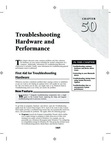
Balboa’s Patented M7 TechnologyTOPSIDE CONTROL PANELThe control panel activates functions at the touch of a button.Each function will echo from the circuit board to the LCD ina corresponding manner. The panel will also display diagnostic messages that enable the service technician to easilytroubleshoot the system.ML700 Top Side PanelM7 TECHNOLOGYM7 is a patented Balboa technology that uses two sensorsinserted at the opposite ends of the heater element todetermine flow, dry fire conditions, etc. The two sensorslocated within the heater housing compare the inlet watertemperature with the outlet water temperature. It works nomatter which direction the water flows through the heater.The sensors in combination with specific software allow thespa to be controlled without the use of external pressureswitches, flow switches, or temperature sensors.Panel ConstructionVS501 with a Cut-a-wayView of the HeaterSensor2Sensor
Table of ContentsBalboa’s Patented M7 Technology . . . . . . . . . . . . . .Balboa Service Tools and Parts Checklist . . . . . . . . . . .Important Information -- Product Identification . . . . . . . .Troubleshooting & Servicing Spa and Electrical Equipment . .G.F.C.I. Troubleshooting . . . . . . . . . . . . . . . . .If Correct Wiring is Verified . . . . . . . . . . . . . . .To Disconnect the Heater . . . . . . . . . . . . . . . .Voltage Checks: Breaker Box, G.F.C.I. & System Box . . . .Wiring Checks . . . . . . . . . . . . . . . . . . . . .Spa Behavior -- Start-up Information . . . . . . . . . . .Priming Mode . . . . . . . . . . . . . . . . . . . .Heater Start up Information . . . . . . . . . . . . . . .Diagnosing M7 Topside Control Panels . . . . . . . . . . . .Checking the System Power Input Fuse . . . . . . . . . .ML Series Panels -- For Use with EL and GL Systems . . . .ML900 Panel Operation . . . . . . . . . . . . . . . . .ML700 Panel Operation . . . . . . . . . . . . . . . . .ML550, 551, 554 Panel Operation . . . . . . . . . . . .ML200, 240, 260, 400 Panel Operation . . . . . . . . . . .VL Series Panels -- For use with VS and GS Systems . . . .VS/GS Panel -- 300 & 500 Series and Operation. . . . . . .EL and GL Series Mach 3 -- Persistent Memory & Power Up .EL - GL, about Persistent Memory . . . . . . . . . . . .Power Up Display Sequence, Software ID . . . . . . . . .VS-GS Persistent Memory with VL Panels . . . . . . . . .Testing the Circuit Board Output . . . . . . . . . . . . .Balboa’s Quick TestTM Test Kit . . . . . . . . . . . . . .To Use the Balboa Quick Check . . . . . . . . . . . . .Testing the Sensor Set . . . . . . . . . . . . . . . . .Changing a System Circuit Board . . . . . . . . . . . . .How to Remove a System Circuit Board . . . . . . . . . .How to Replace a System Circuit Board . . . . . . . . . .Removing the Heater Assembly from a Spa System . . . . .Panel Message Reference Guide . . . . . . . . . . . . 4040404142424243443
Diagrams (in alphabetical order)300/300F/500Z Series Panel . . . . . . . . . . . . . . . . . . . . . . . . . . . . . . . . . . . . . . . . . . . . . . . . . .34500DZ Series Panel . . . . . . . . . . . . . . . . . . . . . . . . . . . . . . . . . . . . . . . . . . . . . . . . . . . . . . .34500SZ Series Panel . . . . . . . . . . . . . . . . . . . . . . . . . . . . . . . . . . . . . . . . . . . . . . . . . . . . . . .34Balboa QuickCheckTM Part No. 70002 . . . . . . . . . . . . . . . . . . . . . . . . . . . . . . . . . . . . . . . . . . . .40Ground-Fault Circuit Interrupter/Circuit Breaker (G.F.C.I.) . . . . . . . . . . . . . . . . . . . . . . . . . . . . . . . . 8120 Volt Residential Wiring Schematic with G.F.C.I. . . . . . . . . . . . . . . . . . . . . . . . . . . . . . . . . . . . .10240 Volt Residential Wiring Schematic with G.F.C.I. . . . . . . . . . . . . . . . . . . . . . . . . . . . . . . . . . . . .12Ground in System Enclosure . . . . . . . . . . . . . . . . . . . . . . . . . . . . . . . . . . . . . . . . . . . . . . . . . 7Heater Element Specifications Are Shown on the Heater Tube Label . . . . . . . . . . . . . . . . . . . . . . . . . 6ML260, ML240, ML200 . . . . . . . . . . . . . . . . . . . . . . . . . . . . . . . . . . . . . . . . . . . . . . . . . . . . .28ML400 . . . . . . . . . . . . . . . . . . . . . . . . . . . . . . . . . . . . . . . . . . . . . . . . . . . . . . . . . . . . . . .28ML550 . . . . . . . . . . . . . . . . . . . . . . . . . . . . . . . . . . . . . . . . . . . . . . . . . . . . . . . . . . . . . . .24ML551 . . . . . . . . . . . . . . . . . . . . . . . . . . . . . . . . . . . . . . . . . . . . . . . . . . . . . . . . . . . . . . .24ML554 . . . . . . . . . . . . . . . . . . . . . . . . . . . . . . . . . . . . . . . . . . . . . . . . . . . . . . . . . . . . . . .24ML700 Top Side Panel . . . . . . . . . . . . . . . . . . . . . . . . . . . . . . . . . . . . . . . . . . . . . . . . . . . . . 2Recommended Parts For Service Calls . . . . . . . . . . . . . . . . . . . . . . . . . . . . . . . . . . . . . . . . . . . 5Service Tools Required . . . . . . . . . . . . . . . . . . . . . . . . . . . . . . . . . . . . . . . . . . . . . . . . . . . . 5“Molex” Type, ML/GL Connector . . . . . . . . . . . . . . . . . . . . . . . . . . . . . . . . . . . . . . . . . . . . . . 6On Every System, an Identification Label Is Placed on top of the Casing . . . . . . . . . . . . . . . . . . . . . . . . 6On Every System, a Wiring Diagram Is Placed Inside the Door . . . . . . . . . . . . . . . . . . . . . . . . . . . . . 6Panel Construction . . . . . . . . . . . . . . . . . . . . . . . . . . . . . . . . . . . . . . . . . . . . . . . . . . . . . . . 2“Phone Plug” RJ Type, VL/GS Connector . . . . . . . . . . . . . . . . . . . . . . . . . . . . . . . . . . . . . . . . . . 6“Phone Plug” RJ Type, VL/VS Connector . . . . . . . . . . . . . . . . . . . . . . . . . . . . . . . . . . . . . . . . .32Terminal Block 1 & F5 Fuse on a VS500Z Board . . . . . . . . . . . . . . . . . . . . . . . . . . . . . . . . . . . . . .19VS500 Board . . . . . . . . . . . . . . . . . . . . . . . . . . . . . . . . . . . . . . . . . . . . . . . . . . . . . . . . . . .42VS501 with a Cut-a-way View of the Heater . . . . . . . . . . . . . . . . . . . . . . . . . . . . . . . . . . . . . . . . 24
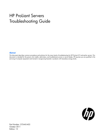
Balboa Service Tools and Parts ChecklistService Tools RequiredUÊUÊUÊUÊUÊAmmeter (50A)Balboa Six-in-one ScrewdriverDigital Multi-meterPadlock (to lock electrical disconnect during service)Pliers: Slip Joint & Needle noseUÊUÊUÊUÊUÊPrecision Thermometer - Digital Fever TypeQuick CheckTM Test KitSilicone TubeSmall Wire CuttersTwo 3/8” Open End Wrenches (one wrench should beground down to 5/32” [0.156”] thickness in order toaccess the nut between the heater strap andheater element connector)20618JUMPER LOGICCOMMON FUSES 144730136FUSE 1 AMP FAST BLOW GLASSFUSE 5 AMP FAST BLOW GLASSFUSE 10A BLOWERFUSE 10A POWER INPUTFUSE 15 AMP FAST BLOW CERAMICFUSE 15A POWER INPUTFUSE 20A POWER INPUTFUSE 20A PUMPFUSE 25A POWER INPUTFUSE 25A POWER INPUT HIGH SURGEFUSE 30A POWER INPUTRecommended PartsFor Service CallsUÊUÊUÊUÊUÊExtra Board(s)Extra Panel(s)FusesJumpersHeater AssemblyMORE COMMON BOARDS:22972 BOARD BARE VS500 (shown)21998 BOARD BARE GL200027116 BOARD BARE EL500053649 ML700Heater Assembly5
Important Information -- Product IdentificationTwo Types of Plug-in Connectors:“Molex” Type,ML/GL ConnectorOn Every System, an IdentificationLabel Is Placed on top of the CasingHeater Element Specifications Are Shownon the Heater Tube LabelOn Every System, a Wiring DiagramIs Placed Inside the Door6“Phone Plug” RJ Type,VL/GS Connector
Troubleshooting & Servicing Spa and Electrical EquipmentHIGH VOLTAGE CAN SERIOUSLY INJURE OR KILL!ONLY EXPERIENCED TECHNICIANS SHOULD SERVICE THIS EQUIPMENT.DO NOT remove the protective covers from any electrical enclosure, or attempt to service anyrelated electrical device, unless you are a qualified electrician or service professional.DANGERRisk of electric shock. Before working with any electricalconnections, make certain that the Main Power breaker fromthe house breaker box has been turned off.WARNINGAll electrical work must be performed by a qualifiedelectrician and must conform to all local codes.IMPORTANTDue to the danger of severe electrical shock, locate allpower disconnects before servicing a spa. Precautions mustbe taken whenever working with breaker boxes, G.F.C.I.’s, orservice disconnects.UÊ Always refer to the wiring diagram which is includedwith each system on the inside of the system box cover.Use this diagram for voltage measurement points, andfor proper reconnection of wires.A terminal marked “GROUND” is provided withinthe System Control Center enclosure. To reducethe risk of electrical shock, connect this terminalto the grounding terminalof the electric supply panelwith a continuous greeninsulated copper wireequivalent in size to thecircuit conductors supplyingthis equipment, but nosmaller than #12 AWG.Ground in System EnclosureSafety TipsUÊ Keep children and pets away.UÊ Be aware of your surroundings. Standing in water whilerepairing a spa puts you at serious risk.UÊ Avoid working in cramped or crowded conditions.UÊ Consider placing a padlock on the service panel to lockout anyone who might power up the system.7
G.F.C.I. TroubleshootingKeep in mind that a majority of G.F.C.I. tripping problems can be attributed to incorrect wiring. G.F.C.I. troubleshooting usually findsthe problem.IF CORRECT WIRING IS VERIFIEDTO DISCONNECT THE HEATERUÊ Check to see if the proper G.F.C.I. is installed.UÊ Check the label in the system box near TB1 to determinethe maximum amperage draw for the system.UÊ Be sure the G.F.C.I. is rated for more amperage than thesystem will draw.UÊ For a 240 V dedicated system, a 2-pole G.F.C.I. with noload neutral is acceptable.UÊ For a 120/240 V system, the G.F.C.I. must include a loadneutral out.UÊ If the white load neutral wire is routed from the G.F.C.I.neutral bar directly to TB1 in the system box, then theG.F.C.I. will trip when a 120 V device is activated.UÊ For a detailed wiring checklist, please review theprevious segment of this manual on proper G.F.C.I. wiringor the G.F.C.I. manufacturer’s instructions.UÊ If the wiring is correct and the G.F.C.I. will not reset, thenunplug the pump and try to reset the G.F.C.I.UÊ If the G.F.C.I. trips again, then unplug the blower andreset the G.F.C.I. If the G.F.C.I. continues to trip, then dothe same procedure for the ozone generator.UÊ If the G.F.C.I. stops tripping after you unplugged one ofthe spa’s components, turn off the power to the spa thenplug in each component except the one that tripped theG.F.C.I.UÊ Power up the system. If the G.F.C.I. no longer trips,then you have correctly identified the problem.Repair or replace the component as instructed bythe spa manufacturer.UÊ If you have unplugged all of the spa’s components andthe G.F.C.I. still doesn’t reset, then the problem is mostlikely a ground fault in the heater.UÊ First, turn off the main circuit breaker, then remove bothheater straps or wires from the system heater output,not the heater itself.UÊ After restoring the power, try to reset the G.F.C.I. again.If it no longer trips after the system calls for heat, thenreplace the heater.UÊ If the G.F.C.I. still trips, look for pinched or shortedwires at the transformer. Make sure that the screwsthat attach the transformer to the system boxhave not pinched or damaged the insulation of thetransformer wires.UÊ If the transformer wires are undamaged, check for anyother pinched wires. Refer to the wiring diagram toverify the correct wiring of the control system.UÊ If everything looks to be in perfect working order, thenthe G.F.C.I. may be defective.WARNING: THE OWNER SHOULD TEST ANDRESET THE G.F.C.I. ON A REGULAR BASIS TOVERIFY ITS FUNCTION.8Ground-Fault CircuitInterrupter/CircuitBreaker (G.F.C.I.)
Voltage Checks: Breaker Box, G.F.C.I. & System BoxWhen checking for proper voltage, keep in mind that the acceptable voltage range is 10% of the recommended voltage.Acceptable voltage when 120 V is specified is between 108 and 132 V.Acceptable voltage when 240 V is specified is between 216 and 264 V.Diagrams are on the following pages.Voltage Verification - Most G.F.C.I. Problems Are Due To Low VoltageIMPORTANT:IF THE VOLTAGE IS NOT WITHIN THE ACCEPTABLE RANGE, CALL AN ELECTRICIANOR THE LOCAL ELECTRIC COMPANY TO DIAGNOSE THE PROBLEM.CHECK THE VOLTAGES AT:1. Breaker Box Voltage Check2. G.F.C.I. Line-In Voltage Check.3. G.F.C.I. Load Out Voltage Check4. System Box Check At Tb1120 VOLT SYSTEMS - 120V 10% - 108V - 132V240 VOLT SYSTEMS - 240V 10% - 216V - 264VNo More Than 2% (5 Volt AC) Difference Between Voltageat the Breaker Panel And Voltage at the System.UÊ CHECK UNDER PEAK LOADS -- TWO TYPES OF PEAK LOADS1. Spa System Peak Loads - Pumps, Heater, Blower & Light On2. Household Peak Loads - May Be In Afternoon On Hot DayUse Recording Meter If Possible - Records Max & Min VoltsUÊ -/, Ê " /," Ê-9-/ Ê, /Ê --1 -Communication Between Topside & System Board In Most SystemsPress Button - Message Sent To System BoardSystem Board Performs - Message Sent Back To Topside & Relay Opens Or ClosesLED or Icon Is Turned On or Off - Hear Or See Relay Open Or CloseIn Most Cases, If This Happens, There Is No Problem With The Topside Panel Or System BoardUÊ8 * ÊÊ ÊÊ-* Ê /Ê -Ê "/Ê7", ÊÊ ÊÊÓÊ",ÊÎÊ -9Ê-/ *-Êt1. Press Light ButtonLight LED or Icon Turns ON, But Spa Light Is NOT ONTopside & Board Are Good, Check DownstreamLight LED or Icon Is NOT ONTopside Or System Board May Be Bad, Continue2. Plug In Spare Topside Panel - Easier To Check For Bad TopsideLight LED or Icon Now Turns ONOriginal Topside Is Bad - R&R Topside PanelLight LED or Icon Is NOT ONOriginal Topside Is Good, Do Not ReplaceSystem Board Is Bad - R&R System Board3. Spa Light Is Still NOT ON - Check DownstreamSame Procedure For Other FunctionsJets, Blower, Heater, Time, Program, Mode, Etc.Diagrams Are On The Following Pages.9
120 Volt Residential Wiring Schematic with G.F.C.I.G.F.C.I Breaker Box120 VACNeutral120 VACHouse Breaker NONON10OFFONONOFFOFFOFFONOFF65ONON11ONON794Outside Ground RodCorrectVoltage0v108V - 132V10When Probes Are Placed Across[2 - 3] [4 - 6] [4 - 7] [5 - 8] [9-10][1 - 3] [4 - 5] [4 - 8] [5 - 6] [5 - 9][6 - 8] [7 - 8] [9 - 11] [10 - 11]
Spa System Box 120VAC ServiceBottom view of G.F.C.ICLASS G FUSE 30AK6F5J73GCWHT ACJ11J25 A MAX 60HzHOTBLACKHOTBLACKTORQUERANGEFOR TB1:27-30 IN. LBS.HOTREDHOTREDUSE ONLYCOPPERCONDUCTORS:#6 AWG MIN.K4F4 FUSE .3A 250V21K3K2TB1J32 J33Black (Hot)White WhiteF2RED UERANGEFOR TB1:27-30 IN. LBS.HOTREDHOTREDCCE.GNDK5W2W7F1FUSE 3A 250VGGGJ20J1J2J18NEUTRALWHITE120/240VAC16/40A MAX 60HzT1F4 FUSE .3A 250VW2CCCGW1USE ONLYCOPPERCONDUCTORS:#6 AWG MIN.J29J4712VLightJ25 J63J15J29K1J73OzoneJ11J23GK6F5WHT ACW4CLASS G FUSE 30AK4K3K2TB1SWITCHBANK AU4S1 TSTSEN. AJ32 J33J43HTR2HTR1E.GNDF2RED ACBalboaSEN. BMADE IN U.S.ACOPYRIGHT 2005J6J7J8BALBOA INSTRUMENTS INC.VS500ZP/N 22972 REV D4.0 kWHOTREDHOTREDHOTBLACKTORQUERANGEFOR TB1:27-30 IN. LBS.HOTBLACKNEUTRALWHITE120/240VAC16/40A MAX 60HzNEUTRALWHITEUSE ONLYCOPPERCONDUCTORS:#6 AWG MIN.K4TB1Test for Voltages by placingprobes on these locationsJ32 J33Electric Installation 120VAC 092608.eps11
240 Volt Residential Wiring Schematic with G.F.C.I.G.F.C.I Breaker Box10120 VACNeutral120 VACHouse Breaker tside Ground RodCorrectVoltage0v12When Probes Are Placed Across[3 - 4] [5 - 8][5 - 9][12 - 13]108V - 132V[1 - 3] [5 - 6][2 - 3] [5 - 7][5 - 10][5 - 11][12 - 14][12 - 15]216V - 264V[1 - 2] [6 - 7][10 - 11][14 - 15][13 - 14][13 - 15]
Spa System Box 240VAC ServiceBottom view of G.F.C.ICLASS G FUSE 30AK6F5J73GCWHT ACJ11J25 A MAX 60HzHOTBLACKHOTBLACKTORQUERANGEFOR TB1:27-30 IN. LBS.HOTREDHOTREDUSE ONLYCOPPERCONDUCTORS:#6 AWG MIN.Black (Hot)7K4F4 FUSE .3A 250V2K3K2TB1White White31J32 J33F2RED ACRed OTREDHOTREDCGCE.GNDK5W2W7F1FUSE 3A 250VGGJ20J1J2J18NEUTRALWHITETORQUERANGEFOR TB1:27-30 IN. LBS.T1F4 FUSE .3A 250VCCCGW1USE ONLYCOPPERCONDUCTORS:#6 AWG MIN.120/240VAC16/40A MAX 60HzJ29J47W212VLightJ25 J63J15J29K1J73OzoneJ11J23GK6F5WHT ACW4CLASS G FUSE 30AK4K3K2TB1U4S1 TSTSWITCHBANK ASEN. AJ32 J33MADE IN U.S.ACOPYRIGHT 2005J43HTR2HTR1E.GNDF2RED ACBalboaSEN. BJ6J7J8BALBOA INSTRUMENTS INC.VS500ZP/N 22972 REV D4.0 kWHOTREDHOTREDHOTBLACKTORQUERANGEFOR TB1:27-30 IN. LBS.HOTBLACKNEUTRALWHITE120/240VAC16/40A MAX 60HzNEUTRALWHITEUSE ONLYCOPPERCONDUCTORS:#6 AWG MIN.K4TB1Test for Voltages by placingprobes on these locationsJ32 J33Electric Installation 240VAC 092608.eps13
Wiring ChecksSYSTEM BOX WIRE GAUGE CHECKWIRING CHECK PRECAUTIONSUÊ When working in a system box always be aware that itmay contain high voltage.UÊ Always keep your fingers and hand tools away from anywiring or circuit board when the power is on. Touchinganything in these areas can result in serious injury.UÊ All service calls, no matter how minor, should include a complete wiring check, beginning with thehouse breaker.CHECK FOR LOOSE CONNECTIONS ORDAMAGED WIRESIMPORTANTUÊ Make sure the power is off before you touch any wiring.UÊ Once the power is off, carefully examine all wires forcuts or defects.CLASS G FUSE 30AF5BLK ACJ61J62J11J16 J25 J63 J64J15NEUTRALWHITETB1HOTBLACKTORQUERANGEFOR TB1:27-30 IN. LBS.HOTREDK4Using non-copper wire can be dangerous, and also can bethe cause of a spa’s malfunction. If non-copper wireis used at any point, we do not recommend servicing thespa until an electrician replaces it with the proper gaugecopper wire.IMPORTANTWHT ACJ66 J65When inspecting the wiring for any control system, notethat connections for the incoming wires are clearly labeledat the main terminal block.UÊ 30A service – minimum ten gauge copper wire.UÊ 40A service – minimum eight gauge copper wire.UÊ 50A service – minimum six gauge copper wire.These wires must connect the house breaker box,through the local disconnect, to the main terminal block.The wiring diagram inside the system box shows the mainterminal block as TB1.This service must be single phase. Any abnormal voltage reading requires an electrician. Do not attempt to fixthese types of problems yourself. High voltage canseriously injure or kill.TB1J32 J33 J34J36J35J37RED ACBalboaPower SystemMinimum wire sizeUse Copper ONLY,with 90 o C insulationAmpere Rating ofG.F.C.I. Circuit-breaker0 A to 16 A#12 AWG2016 A to 20 A#10 AWG2520 A to 24 A#10 AWG3024 A to 28 A#8 AWG3528 A to 32 A#8 AWG4032 A to 36 A#6 AWG4536 A to 40 A#6 AWG50Total Ampere Rating of14
Spa Behavior -- Start-up InformationSee manufacturer’s owners manual or reference card for general information on operating the spa, including programmingfilters and other settings that are changed from the topside control panel.PRIMING MODEHEATER START UP INFORMATIONIn Priming Mode, the “Mode” button toggles the ozone on/off(with a 15-second time-out). This can be useful if you want toverify ozone generator operation without waiting for a filtercycle. This feature is not available on smaller panels whereMode is a multi-button sequence, since such a sequenceexits Priming Mode.On M-7 systems, the heater goes through a testing phaseevery time it starts up to assure that there is adequatewater flow. This provides sophisticated dry fire and low flowprotection. It can be confusing if you don't know what toexpect. Step by step, here is what happens. (Note that thetiming/temperature details may be slightly different on someolder M7 systems.)UÊ Prior to heating, the pump is run for at least twominutes, and then the temperature difference betweenthe sensors is assessed. It must be 2 F/1.0 C or less forheating to proceed, otherwise an error is issued.UÊ The heater turns on for 6.5 to 18 seconds (dependingon heater voltage and wattage). At this point, the heatindicator on the panel is "solid." During this time thepanel is not immediately responsive.UÊ The heater turns off for 90 seconds, making sure that thewater flow keeps the temperature rise small and short.(Abnormal water flows, or lack of water, will producea large and/or long temperature rise, and the systemfaults in that situation.) At this point, the heat indicatoron the panel may appear to "shimmer" or "dim" (on somepanels this may be less obvious from certain angles andmore obvious from other angles, or in different lighting).UÊ If the dry fire test has passed, heating turns back on toheat the spa. The heat indicator on the panel returnsto "solid".UÊ During spa heating, a difference between the sensorsof 2 F/1.0 C, or perhaps 3 F/1.5 C (at least with 4-6kW240V heaters), is considered normal. A significantlyhigher difference, however, is usually indicative of aflow problem, and will cause a fault which disablesthe heating for at least a minute (and then restarts thewhole above process).GENERAL FILTER INFORMATIONUÊ On any system with a Deluxe panel, the filter timesand durations are completely programmable from thetopside control panel, and the first filter may not runfor many hours after power-up. If you want the filterto run sooner, you have to either reprogram the filter oradvance the time to just before the filter start.UÊ On all other systems, the first filter starts 6 minutes afterpower-up and the duration can be chosen (either usingbutton sequences on the topside control panel or via aDIP switch) between several preset choices. Note that ifyou let Priming Mode exit automatically after 4 minutes,you have 2 more minutes before the first filter runs afterpower-up. Exiting Priming Mode by pressing the “Temp,”Warm,” or “Cool” buttons, allows up to 6 minutesavailable before the firstfilter runs.IMPORTANT INFORMATION: If the filter settings have justbeen changed, it may take up to 24 hours for the filter cycleto reflect the changes. This is especially likely when changingfrom a very long filter duration (such as Continuous), to ashort one, or vice versa.UÊ The low-speed pump (on non-circ) and ozone generator(if installed) will run during the filter cycles.UÊ The blower runs for 30 seconds at the start of each filtercycle. This will maintain water quality in the air channel.UÊ The pumps (other than pump 1 in non-circ, includingpump 1 in circ) will run for 5 minutes at the start of eachfilter cycle.15
Diagnosing M7 Topside Control PanelsPanel messages are a quick clue toward solving a variety of problems. Here are the most common messages and whatthey mean.PRELIMINARY PANEL CHECKUÊ If the problem is not obvious, look on the topside controlpanel for diagnostic messages.If no messages are seen, run through all spa functionsand note any inconsistent operation.UÊ Most error messages are stored in the fault log. To viewthe fault log, the spa must be in test mode and the spalight must be turned on.Once you have determined that proper voltage is runningthrough the circuit board and transformer, continue to thetopside control panel. A panel that is not functioning properlymay include the following symptoms: low voltage such asmissing or scrambled segments, missing icons on the LCD,non-functional LED’s, or nonfunctional buttons. If any of thesesymptoms are present, perform the following:UÊ Turn the power off and unplug the panel from thecircuit board.UÊ Then, plug in your test panel and restore power. If everything functions normally, replace the topside panel.UÊ Disconnect ozone generator (if applicable).UÊ If you still see symptoms of low voltage, such as asluggish, blank or partially blank panel, or if the displayor the LED’s do not function at all, turn the power off;unplug the ozone generator (if equipped); then restorepower to the system. If the problem persists, turn off thepower and replace the circuit board.16PANEL DISPLAY MESSAGESTHE PANEL DISPLAYS:,, orAt least one of the sensors has detected water temperaturesof 118ºF inside the heater. Or,THE PANEL DISPLAYS:,, orOne of the sensors has detected the temperatureof the water coming into the heater to be 110ºF,and so the water in the spa is likely to be that hot.These indicate that the spa has shut down due to anoverheat situation.NOTE: Overheating may occur if the low-speed pump is setto operate for extended periods of time, or if the incorrectpump is installed. In rare cases (usually warmer climates), thecirculation pump may also cause overheating.MOST PROBABLE OVERHEATING CAUSES,INSPECT THESE FIRSTUÊ Check slice or ball valves. Make sure that theyare open.UÊ Make sure the correct pump is installed.UÊ Clean the filter/skimmer if there is any blockage.UÊ Check heater element alignment.UÊ Check for debris on the heater element.UÊ In extremely hot weather, check for propercabinet ventilation.UÊ Make sure the temperature sensor is fully insertedinto the sensor fitting on the heater.UÊ Check for excessive filter duration.
NOTE: A common programming mistake is overlapping filtertimes that may cause the spa to filter continuously.UÊ Check the water level.UÊ Check the water temperature with an accuratetemperature thermometer. Remove the spa cover andallow the water to cool to below 108 F. Adding coolwater may be necessary. Touch any button to resetthe system. If the water is still hotter than the settemperature, press the blower button (if applicable) tocool the spa.If the Problem Recurs, test the Sensor Set.THE PANEL DISPLAYS:,,, ororTHE PANEL DISPLAYS:THE PANEL DISPLAYS:,, orIndicates the sensor detects a possible freeze condition.This Freeze Condition message does not appear on M-7software showing a Software Version ID of 01 or greater. Thisis a normal spa function; no further action is necessary.When either sensor reads below 40 F, the systemprovides freeze protection. It automatically activates thepump (and the heater if necessary) to circulate the water andwarm the plumbing. The equipment stays on until the sensorsdetect that the spa temperature has risen to within 15ºF ofthe set temperature. The other pumps and the blower willpurge for 30 seconds to 2 minutes at the end of the freezecondition. If pump 1 was turned on due to this reason alone,this message will appear for up to two minutes right aftervery cold water is detected.NOTE: In rare cases, rapid system overheat causes sensorerror messages. Be sure to rule out possible situations like noflow or no water.NOTE: Internal freeze protection only functions when thereis proper power running to the spa, and the control systemis operational. Using an optional freeze sensor may benecessary in extreme climates to prevent plumbing damage,but will only work properly if placed inside the spa skirt in thecoldest area.All spa models are different in shape and size andhave different thermal characteristics; therefore,Balboa Water Group cannot be held responsiblefor freeze damage to the spa’s plumbing. Testingis the responsibility of the spa manufacturer andmust be done to determine the best location for thefreeze sensor.THE PANEL DISPLAYS:THE PANEL DISPLAYS:,,, ororThis indicates that the spa has shut down due to an open orfaulty sensor. If the problem recurs, test the sensor set. (SeeTesting the Sensor Set.),, orThis indicates that the sensors are out of balance.If alternating with temperature, it may just be a temporarycondition. If flashing by itself, spa is shut down.If the panel also displays “Service Req’,” spa is shut down.If the spa shuts down due to this error, one (or both) of thesensors are probably reading several degrees off. If theproblem recurs, test the sensor set.,, orThis indicates that the auxiliary sensor detects apossible freeze condition. This is a normal spa function;no further action is necessary.When the auxiliary sensor reads around 40 F (actualtemperature dependent on specific auxiliary sensor used), thesystem provides freeze protection. It automatically activatesall of the pumps and the blower to circulate water and warmthe plumbing.17
Diagnosing M7 Topside Control Panels (cont.)NOTE: This auxiliary freeze protection functions at all times,even when another fault condition has occurred and hasotherwise shut the spa down.Any time the lower of the two temperature sensorsgoes below 45 F, all pumps/blowers turn on. They continueto run for 4 minutes after the temperature reaches 45 For above. As soon as the temperature falls below 45 Fagain, this process restarts. This “simplified” sensor freezeprotection functions at all times, even when another faultcondition (other than total sensor failure) has occurred andhas otherwise shut the spa down.THE PANEL DISPLAYS:,, orThis indicates that a substantial difference intemperature between sensors has been detectedduring heating.This could indicate a flow problem. Check water level in spa.Refill, if necessary. If the water level is okay, make sure thepumps have been primed. On the fifth occurrence ofthe above message the panel will display:, orThis indicates a persistent flow problem. The heateris shut down while all other spa functions continue to runnormally. Power on the spa must be cycled before t
Light LED or Icon Now Turns ON Original Topside Is Bad - R&R Topside Panel Light LED or Icon Is NOT ON Original Topside Is Good, Do Not Replace System Board Is Bad - R&R System Board 3. Spa Light Is Still NOT ON - Check Downstream Same Procedure For Other