Transcription
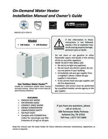
Installation and Operating Instruction ManualWith Installation Instructions for the InstallerDirect Vent Gas - 199,000 Btu InputTankless Water HeaterWarning: This water heater is not suitablefor use in manufactured (mobile) homes!The purpose of this manual is twofold: one, to provide the installer withthe basic directions and recommendations for the proper installation andadjustment of the water heater; and two, to the owner–operator, toexplain the features, operation, safety precautions, maintenance andtroubleshooting of the water heater. This manual also includes a partslist.It is very important that all persons who are expected to install, operateor adjust this water heater read the instructions carefully so they mayunderstand how to perform these operations. If you don’t understandthese instructions or any terms within it, seek professional assistance.Any questions regarding the operation, maintenance, service orwarranty of this water heater should be directed to the seller from whomit was purchased, local distributor or Paloma.Do not destroy this manual. Please read carefully and keep in a safeplace for future reference.Recognize this symbol as an indication of Important SafetyInformation!California Proposition 65 Warning: This product containschemicals known to the State of California to cause cancer, birthdefects or other reproductive harm.WARNING: If the information in these instructions is not followed exactly,a fire or explosion may result causing property damage, personal injury or death.FOR YOUR SAFETY!— Do not store or use gasoline or otherflammable vapors or liquids or othercombustible materials in the vicinity of this orany other appliance. To do so may result in anexplosion or fire.— WHAT TO DO IF YOU SMELL GASl Do not try to light any appliance.l Do not touch any electrical switch; do notuse any phone in your building.l Immediately call your gas supplier from aneighbor’s phone. Follow the gassupplier’s instructions.l If you cannot reach your gas supplier, callthe fire department.l Do not return to your home until authorizedby the gas supplier or fire department.— Improper installation, adjustment,alteration, service or maintenance can causeproperty damage, personal injury, or death.Refer to this manual. Installation and servicemust be performed by a qualified installer,service agency or the gas supplier.Models: PH-28R DVSN (Natural Gas) (Residential)PH-28R DVSP (L.P. Gas) (Residential)PH-28C DVSN (Natural Gas) (Commercial)PH-28C DVSP (L.P. Gas) (Commercial)
Safety InformationFOR YOUR RECORDSSafety Precautions. . . . . . . 3–6Write the model and serial numbers here:LP Gas Models . . . . . . . . . . . 5##Installation InstructionsYou can find them on a label on the appliance.Location of Water Heater . 7, 8Staple sales slip or cancelled check here.Venting . . . . . . . . . . . . . . . 9-15Proof of the original purchase date is needed to obtain serviceunder the warranty.Water Connections. . . . . 16-18Gas Supply . . . . . . . . . . . . . . 19High Altitude . . . . . . . . . . . . 19Remote Control . . . . . . . 20, 21Electrical Connection . . . . . . 22Typical Installation . . . . . . . . 23Pipe Insulation . . . . . . . . . . . 24Installation Checklist . . . 24, 25READ THIS MANUALInside you will find many helpful hints on how to use andmaintain your water heater properly. A little preventive care onyour part can save you time and money over the life of yourwater heater.You’ll find many answers to common problems in theTroubleshooting Guide. If you review the chart ofTroubleshooting Tips first, you may not need to call for service.Operating InstructionsLighting Instructions . . . . . . 26Water Temperature. . . . . 27, 28Care and CleaningMaintenance. . . . . . . . . . . . . 29Housekeeping . . . . . . . . 29, 30Vent Inspection . . . . . . . . . . . 30Burner Inspection . . . . . . . . 30READ THE SAFETY INFORMATIONYour safety and the safety of others are very important. Thereare many important safety messages in this manual and onyour appliance. Always read and obey all safety messages.This is the safety alert symbol. Recognize this symbolas an indication of Important Safety Information!This symbol alerts you to potential hazards that cankill or hurt you and others.Extended Shut-Down. . . . . . 30Draining . . . . . . . . . . . . . . . . 31Freeze Protection . . . . . . . . . 31Troubleshooting TipsAll safety messages will follow the safety alert symbol andeither the word “DANGER”, “WARNING”, “CAUTION” or“NOTICE”.These words mean:DANGERAn imminently hazardous situationthat will result in death or seriousinjury.WARNINGA potentially hazardous situation thatcould result in death or serious injuryand/or damage to property.CAUTIONA potentially hazardous situation thatmay result in minor or moderateinjury.Before You CallFor Service . . . . . . . . . . 32, 33Customer ServiceParts List . . . . . . . . . . . . . . . 34If You Need Service . . . . . . . 36Notice:Qualified Installers Only!Dip Switch Adjustment. . . . 35Warranty.37, 382Attention is called to observe aspecified procedure or maintaina specific condition.
IMPORTANT SAFETY INFORMATIONREAD ALL INSTRUCTIONS BEFORE USING.Be sure to read and understand the entire Instruction Manual before attempting to install or operatethis water heater. It may save you time and money. Pay particular attention to the Safety Instructions.Failure to follow these warnings could result in serious bodily injury or death. Should you haveproblems understanding the instructions in this manual, or have any questions, STOP, and get helpfrom a qualified service technician, or the local gas utility.DANGER!INSTALL AND PROPERLY VENT THE WATER HEATER Failure to install and properly vent the water heater to the outdoors as outlined in theVenting Section of the Installation Instructions in this manual can result in unsafeoperation of the water heater. To avoid the risk of fire, explosion, or asphyxiation fromcarbon monoxide, never operate this water heater unless it is properly vented and has anadequate air supply for proper operation.Be sure to inspect the vent terminal, vent, and the air intake system on the water heaterfor proper installation at initial start-up; and at least annually thereafter. Properoperation of the water heater requires air for combustion. Provisions for combustion airmust comply with referenced codes and standards. Refer to the Care and Cleaning sectionof this manual for more information regarding vent and air intake system inspection.WARNING!Gasoline, as well as other flammable materials and liquids (adhesives, solvents, paintthinners etc.), and the vapors they produce are extremely dangerous. DO NOT handle,use or store gasoline or other flammable or combustible materials anywhere near or in thevicinity of a water heater or any other appliance. Be sure to read and follow the labels onthe water heater, as well as the warnings printed in this manual. Failure to do so canresult in property damage, bodily injury or death.3
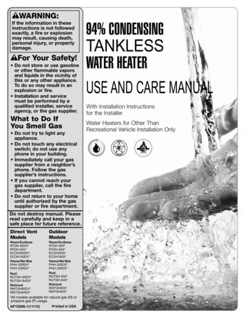
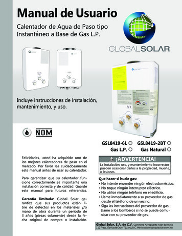
IMPORTANT SAFETY INFORMATIONREAD ALL INSTRUCTIONS BEFORE USING.DANGER!WATER TEMPERATURE SETTINGSafety and energy conservation are factors to be considered when selecting the watertemperature setting of a water heater’s remote control. Water temperatures above125 F (52 C) can cause severe burns or death from scalding. Be sure to read and follow thewarnings outlined on the label pictured below.Time/Temperature Relationship in ScaldsWater TemperatureTime To Produce a Serious Burn120 F (49 C)125 F (52 C)130 F (54 C)135 F (57 C)140 F (60 C)145 F (63 C)150 F (66 C)155 F (68 C)More than 5 minutes11/2 to 2 minutesAbout 30 secondsAbout 10 secondsLess than 5 secondsLess than 3 secondsAbout 11/2 secondsAbout 1 secondTable courtesy of Shriners Burn InstituteThe chart shown above may be used as a guidein determining the proper water temperature foryour home.DANGER: Households with small children,disabled, or elderly persons may require a120 F (49 C) or lower temperature setting toprevent contact with “HOT” water.Maximum water temperature occurs while burner ison. To find water temperature being delivered, turnon a hot water faucet and place a thermometer in thewater stream and read the thermometer.(See page 27 & 28 for more details.)The temperature of the water at the outlet of thewater heater can be regulated by setting thetemperature on Remote Control. The remote controlwas set at 100 F (38 C) before it was shipped fromthe factory.Notice:Displayshows F only.Notice: Only commercial model water heaters canachieve temperatures up to 180 F (82 C).* Temperatures above 120 F (49 C) can be achievedby adjusting the dip switch. See page 35 for dipswitch adjustment.4The Figure to the bottom left illustrates the RemoteControl and how to adjust the water temperature.Notice: The factory setting allows operatingtemperatures between 100 F (38 C) and 120 F(49 C). Temperatures of up to 140 F (60 C) forResidential models and up to 180 F (82 C) forCommercial models can be achieved with theMAIN (UMC-117) remote control and a dip switchadjustment. Only qualified service personnel shouldperform this adjustment. Only factory authorizedremote control(s) should be used.Notice: When this water heater is supplying generalpurpose hot water requirements for use byindividuals, a thermostatically controlled mixingvalve for reducing point of use water temperature isrecommended to reduce the risk of scald injury.Contact a licensed plumber or the local plumbingauthority for further information.
DANGER!NATURAL GAS AND LIQUEFIED PETROLEUM MODELSBoth LP and natural gas have an odorant added to aid in detecting a gas leak. Somepeople may not physically be able to smell or recognize this odorant. If you are unsure orunfamiliar with the smell of LP or natural gas, ask the gas supplier. Other conditions, suchas “odorant fade”, which causes the odorant to diminish in intensity, can also hide orcamouflage a gas leak.l Water heaters utilizing LP gas aredifferent from natural gas models. Anatural gas water heater will not functionsafely on LP gas and vice versa.l No attempt should ever be made toconvert the water heater from naturalgas to LP gas. To avoid possibleequipment damage, personal injury orfire, do not connect the water heater to afuel type not in accordance with the unitdata plate; propane for propane unitsand natural gas for natural gas units.These units are not certified for anyother fuel type.l LP appliances should not be installedbelow grade (for example, in a basement)if such installation is prohibited byfederal, state and/or local laws, rules,regulations or customs.Notice: If a gas leak is present or suspected:l Do not attempt to find the cause yourself.l Do not try to light any appliance.l Do not touch any electrical switch.l Do not use any phone in your building.l Leave the building immediately andmake sure your family and pets leavealso.l Leave the doors open for ventilation andcontact the gas supplier, a qualifiedservice agency or the fire department.l Stay away from the building until theservice call has been made, the leak iscorrected and a qualified agency hasdetermined the area to be safe.l Propane or LP gas must be used withgreat caution. It is heavier than air andwill collect first in lower areas making ithard to detect at nose level.l Before attempting to light the waterheater, make sure to look and smell forgas leaks. Use a soapy solution to checkall gas fittings and connections. Bubblingat a connection indicates a leak that mustbe corrected. When smelling to detect agas leak, be sure to sniff near the flooralso.l Gas detectors are recommended in LPand natural gas applications and theirinstallation should be in accordance withthe detector manufacturer’srecommendations and/or local laws,rules, regulations or customs.l It is recommended that more than onemethod, such as soapy solution, gasdetectors, etc., be used to detect leaks ingas applications.5
IMPORTANT SAFETY INFORMATIONREAD ALL INSTRUCTIONS BEFORE USING.WARNING!For your safety, the information in this manual must be followed to minimize the risk offire or explosion, electric shock, or to prevent property damage, personal injury, or loss oflife.NOTICE: This water heater requires a special venting system. Refer to the instructionsin the vent section for proper vent material and method of installation.FOR INSTALLATIONS IN THE STATE OF CALIFORNIACalifornia Law requires that water heaters must be braced, anchored or strapped toresist falling or horizontal displacement due to earthquake motions. For water heaters upto 52 gallon capacity, a brochure with generic earthquake bracing instructions can beobtained from: Office of the State Architect, 1102 Q Street, Suite 5100, Sacramento, CA95814 or you may call 916-445-8100 or ask a water heater dealer.However, applicable local codes shall govern installation. For water heatersof a capacity greater than 52 gallons or tankless-style, consult the local buildingjurisdiction code for acceptable bracing procedures.SAFETY PRECAUTIONSHave the installer show you the location of the gas shut-off valve and how to shut it off ifnecessary. Turn off the manual shut-off valve if the water heater has been subjected tooverheating, fire, flood, physical damage or if the gas supply fails to shut off.l Read this manual entirely beforeinstalling or operating the water heater.l Use this appliance only for its intendedpurpose as described in this Use andCare Manual.l Do not attempt to repair or replace anypart of your water heater unless it isspecifically recommended in thismanual. All other servicing should bereferred to a qualified technician.l Be sure your appliance is properlyinstalled in accordance with local codesand the provided installationinstructions.READ AND FOLLOW THIS SAFETY INFORMATIONCAREFULLY.SAVE THESE INSTRUCTIONS6
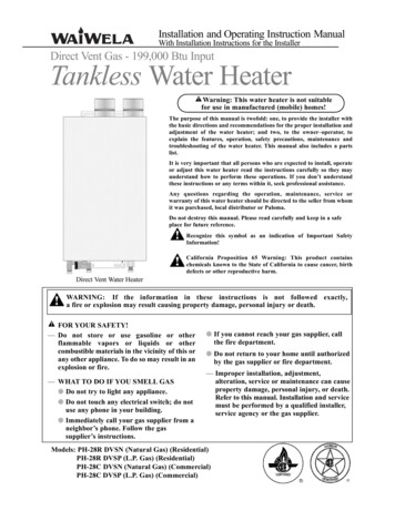
Installing the water heater :This water heater must be installed in accordance with these instructions, local codes, utility companyrequirements, and/or in the absence of local codes, use the latest edition of the American NationalStandard/National Fuel Gas Code. A copy can be purchased from either the American Gas Association,400 North Capitol Street Northwest, Washington, DC 20001 as ANSI standard Z223.1 or National FireProtection Association, 1 Batterymarch Park, Quincy, MA 02269 as NFPA 54. In Canada, the latestedition of the CSA B149.1 Natural Gas and Propane Installation, and the Canadian Electrical Code,CSA C22.1 Part 1, in the absence of local codes.Location of Water HeaterThe water heater should not be locatedin an area where leakage of the heatexchanger or connections will result indamage to the area adjacent to it or tolower floors of the structure.When such areas cannot be avoided it isrecommended that a suitable catch pan,adequately drained, must be installedunder the water heater.The pan must not restrict combustion airflow.WARNING: Combustibleconstruction refers toadjacent walls and ceilingsand should not be confusedwith combustible orflammable products andmaterials. Combustibleand/or flammable productsand materials should neverbe stored in the vicinity ofthis or any gas appliance.A gas fired water heater or any otherappliance should not be installedin a space where liquids which give offflammable vapors are to be used or stored.Such liquids include gasoline, but are notlimited to, LP gas (butane or propane),paint or adhesives and their thinners,solvents or removers.Because of natural air movement in a roomor other enclosed space, flammable vaporscan be carried some distance from wheretheir liquids are being used or stored. Theopen flame of the water heater’s mainburner can ignite these vapors causing anexplosion or fire which may result in severeburns, death or property damage.The water heater must be located so it is notsubject to physical damage, for example, bymoving vehicles, area flooding, etc.If the water heater is installed in a garage, itshould be installed so that the directignition system and main burner are no lessthan 18 inches (45 cm) above the garagefloor.Raising the gas fired water heater willreduce BUT NOT eliminate the possibilityof lighting the vapor of any flammableliquids which may be improperly stored oraccidentally spilled.l The water heater should be installed asclose as practical to the vent terminationto minimize vent length and the numberof elbows required for venting.l The water heater should be installed withthe proper venting materials andtermination suitable for Category IIIventing.l A fire stop plate should be installed atevery penetration of a floor or ceiling ifthe vent is not running in a fire-ratedshaft.l Failure to install and properly vent thewater heater to the outdoors as outlinedin the Venting Section of this manual canresult in unsafe operation.l Long hot water lines should be insulated toconserve water and energy.l The water heater and water lines shouldbe protected from exposure to freezingtemperatures.l Do not install the water heater inbathrooms, bedrooms, any occupiedrooms normally kept closed, or inoutdoor areas.l Do not install the water heater in small,poorly ventilated rooms, or in air tightrooms with air-conditioning.l Do not install water heater where subjectto vibrations.l Do not install the water heater inRecreational Vehicles, Mobile Homes,Boats and other Watercrafts.l Do not install the water heater near ventsfor heating or cooling. A minimum of 4feet (1.2 m) should be maintained.l Minimum clearance from combustibleand non-combustible construction is 0”around the air intakes pipe, 1/2” (1.3 cm)sides, 0” rear (with support bracket); 12”(30 cm) from the bottom; 12” (30 cm)from the front of the water heater; and12” (30 cm) from the top, (24” (61 cm)from front and top is recommended forservicing purposes). Refer to Figure onpage 8.l Maintain a minimum clearance of1” (2.5 cm) between the vent outlet pipeand air intake pipe. Also, maintain a 3”(8 cm) clearance between the vent pipeand combustible or non-combustibleconstruction, unless otherwise specifiedby vent manufacturer or installed in anenclosed space. If the clearances statedon the Instruction/Warning Label,located on the front panel of the heaterdiffer, install the water heater accordingto the clearances stated on the label.Refer to Figure on page 8.7
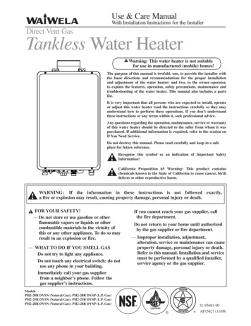
Installing the water heater:Location of Water Heater continued:Notice: Maintain a1/4” Per foot downwardslope towards termination3” (8 cm) clearancebetween the vent pipeand combustible ornon-combustibleconstruction.AirIntake PipeVentOutlet Pipe1” (2.5cm) min.between vent outletand air intake pipe.Max. 3’(91 cm)Air intake/Vent pipetermination - shouldbe sloped downwardWARNING: Followvent manufacturersinstruction whileinstalling vent. Ifrequired, provideadditional clearancesfrom vent tocombustibles per ventmanufacturersinstruction.NOTICE: The water heatershould not be installed nearan air supply containinghalogenated hydrocarbons.VentOutletMinimum Clearance fromCombustible and NonCombustible Construction.AirIntakeTop 12"(30 cm)Back 0" *Vent 3" (8 cm)Side 1/2" (1.3 cm)Front 12"(30 cm)Bottom 12" (30 cm)Air Intake 0”* (with support bracket)Corrosive AtmospheresThe air in beauty shops, dry cleaningestablishments, photo processing labs,and storage areas for liquid and powderedbleaches or swimming pool chemicalsoften contain such halogenatedhydrocarbons.An air supply containing halogenatedhydrocarbons may be safe to breathe,but when it passes through a gas flamecorrosive elements are released thatwill shorten the life of any gas burningappliance.Propellants from common spray cans orgas leaks from A/C and refrigerationequipment are highly corrosive afterpassing through a flame.The water heater warranty is voided whenfailure of the heater is due to operation ina corrosive atmosphere.Inspect ShipmentInspect the water heater for possible damage. Check the markings on the rating plate ofthe water heater to be certain the type of gas supplied corresponds to the water heaterrequirements. Verify all included parts are present (see below).Use & Care ManualWith Installation Instructions for the InstallerTankless Water HeatersResidential GasWarning: This water heater is not suitable foruse in manufactured (mobile) homes!The purpose of this manual is twofold: one, to provide the installer withthe basic directions and recommendations for the proper installation andadjustment of the water heater; and two, to the owner–operator, toexplain the features, operation, safety precautions, maintenance andtroubleshooting of the water heater. This manual also includes a partslist.PRIORITYIt is imperative that all persons who are expected to install, operate oradjust this water heater read the instructions carefully so they mayunderstand how to perform these operations. If you don’t understandthese instructions or any terms within it, seek professional advice. FWood Screw x 5pcs.!Recognize this symbol as an indication of Important SafetyInformation!!California Proposition 65 Warning: This product containschemicals known to the State of California to cause cancer, birthdefects or other reproductive harm.WARNING: If the information in these instructions is not followed exactly,a fire or explosion may result causing property damage, personal injury or death.! FOR YOUR SAFETY!— Do not store or use gasoline or otherflammable vapors or liquids or othercombustible materials in the vicinity of this orany other appliance. To do so may result in anexplosion or fire.ON/OFF8Do not destroy this manual. Please read carefully and keep in a safeplace for future reference.!POWERDrain TubingAny questions regarding the operation, maintenance, service orwarranty of this water heater should be directed to the seller from whomit was purchased. If additional information is required, refer to thesection on How to Obtain Service Assistance.— WHAT TO DO IF YOU SMELL GASl Do not try to light any appliance.l Do not touch any electrical switch; do notuse any phone in your building.l Immediately call your gas supplier from aneighbor’s phone. Follow the gassupplier’s instructions.l If you cannot reach your gas supplier, callthe fire department.l Do not return to your home until authorizedby the gas supplier or fire department.— Improper installation, adjustment,alteration, service or maintenance can causeproperty damage, personal injury, or death .Refer to this manual. Installation and servicemust be performed by a qualified installer,service agency or the gas supplier.DESIGNRemote ControlAssembly KitManual ApplianceUse & Care Manual Gas Shut-off ValvePrinted in USAWasher x 4 pcs.CERTIFIED Tankless Unit
The water heater must be installed with a 4” Diameter UL approved Category III Stainless Steel vent pipe,appliance vent adapter and Paloma approved vent termination.DANGER: Failure toinstall the appliance ventadapter and properly ventthe water heater to theoutdoors as outlined in theVenting section of thismanual will result in unsafeoperation of the waterheater causing death,serious injury, explosion, orfire. To avoid the risk offire, explosion, orasphyxiation from carbonmonoxide, NEVER operatethe water heater unless it isproperly vented and hasadequate air supply forproper operation asoutlined in the Ventingsection of this manual.Notice: Use a 4” DiameterUL approved Category IIIStainless Steel vent materialonly. No other ventmaterial is permitted.VentingThe installation of venting must comply withnational codes, local codes, and the ventmanufacturer’s instructions.Notes on pre-existing vent:The water heater must be vented to theoutdoors as described in these instructions.DO NOT connect this water heater to aChimney. It must be vented separately fromall other appliances.All vent components (adapters, pipe, elbows,terminals, etc.) should be UL1738 CertifiedStainless Steel Venting Material(e.g. AL29-4C).Use a vent pipe with an anti-disconnectionjoints.The use of a High Temperature Silicone(500 F) (260 C) may be required to sealvent connections. To prevent accidental gasexhaust leakage, apply a 1/4” (6 mm) widebead approximately 1/4” (6 mm) from theend and another bead against the joint sideof the stop bead.Follow vent manufacturer’s installationinstructions and their recommendedclearances to combustibles.The unit can be vented either horizontally orvertically.WARNING: Refer topage 7 & 8 for clearancesto combustible material.should be used. DO NOT use wire. (SeeFigure below).Vent pipe runs must be adequately supportedalong both horizontal and vertical runs.The maximum recommended unsupportedspan should be no more than five (5) feet(1.5 m) Support isolation hanging bandsIf the water heater is being installed as areplacement for an existing water heater, athorough inspection of the existing venting andair intake system must be performed prior toany installation work. Verify that the correctmaterials, vent lengths and terminal locations asdetailed in this Instruction manual have beenmet. Carefully inspect the entire venting and airintake system for any signs of cracks orfractures, particularly at the joints betweenelbows or other fittings and the straight runs ofvent pipe. Check the system for signs ofsagging or other stresses in the joints as a resultof misalignment of any components in thesystem. If any of these conditions are found,they must be corrected in accordance with theventing instructions in this manual beforecompleting the installation and putting thewater heater into service.Additional installation information for TheCommonwealth of Massachusetts is located onpage 36.Venting LengthsNumber of90 elbows(bends)MaximumLength ofStraight Pipe147’ 6”(14.4 m)242’ 6”(13 m)MAXIMUM VENT LENGTH - Thesystem will not operate if there is excessiverestriction (pressure drop) in the ventingsystem. A maximum of 47 feet 6 inches(14.4 m) of vent pipe may be used providedthere is only one 90 elbow in the system. Ifadditional elbows are required: two elbowscan be used with 42 feet 6 inches (13 m),and three elbows can be used with 37 feet 6inches (11.4 m) of vent pipe.337’ 6”(11.4 m)A 90 elbow is equivalent to 5 feet (1.5 m)of straight pipe. A 45 elbow is equivalent to2 feet 6 inches (76 cm) of straight pipe.MINIMUM VENT LENGTH - The ventlength may be as short as one 90 elbow, onevent adapter, and a Paloma approved venttermination kit that is installed to theoutdoors through a sidewall.6”1’The vent should be installed with a slightdownward slope of 1/4” per foot ofhorizontal run toward the vent terminal (seeFigure on page 8). This ensures that anycondensate formed during operation of theunit is evacuated from the appliance.9
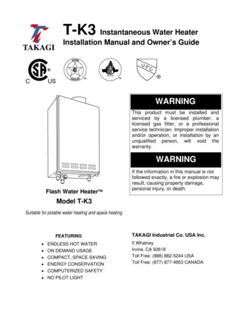
Installing the water heater:The water heater must be installed with an UL approved Category III Stainless Steel appliance vent adapterand Paloma approved vent termination.Air Intake1/4” Per foot downwardslope towards terminationVent Outlet PipeVenting Through Closed SpacesIf the vent piping passes through a closed space, a minimumclearance of 8” (20 cm) when installed horizontally, 6” (15 cm)when installed vertically should be maintained between the ventpipe and combustibles and noncombustibles. Be sure to followlocal codes and vent manufacturers installation instructions.For maintenance and inspection purposes, the following accesspanels are required.Fire StopInspectionAccessPanel #1 CeilingBoardInspectionAccessPanel #2l Two (2) inspection access panels large enough to allowaccess for venting inspection. One (1) of these accesspanels should be close to where the vent pipe enters theceiling. The other access panel should be near the venttermination.l A ventilation access panel with a 16 in2 (103 cm2) openingshould be provided every 10 ft (3 m).Appliance Vent AdapterCAUTION: Ensureappliance vent adapter issecurely attached to thewater heater collar.ExhaustFlowRead the following instructions beforeinstallation.l Test fit the adapter over the waterheater collar before proceeding. Adjustclamp as tA UL 1738 approved stainless steelappliance vent adapter is required for ventconnection.ClampCollarl With an alcohol wipe, clean insidesurface "A" of adapter and outsidesurface of "B" of heater collar.l Apply 1/4" (6 mm) wide bead of hightemperature silicone (500 F) (260 C)around outside of heater collar "B".l Slide adapter end "A" down over heatercollar "B" as far as it will go.l Tighten the clamp around the collar.l Inspect the inside of the adapter toverify that the collar and adapter aresealed. If more sealant is required,apply sealant to a flat tool, then spreadaround the collar edge on inside ofadapter.NOTICE: Follow the appliance ventadapter manufacturer’s instructionsDraining the CondensateCAUTION:Condensateis known to be acidic; referto local, state (provincial)or federal codes for properhandling and dischargemethods.CAUTION: Condensatemust drain away from thewater heater and shouldnot be allowed to drainback into any part of thevent system.WARNING: Failure toprovide a vent condensatedrain close to the appliancecould allow acidic flue gascondensate to enter intoappliance flueways causingpremature failure of theappliance.10Horizontal VentingProvision should be made to collect anddispose of condensate from ventingsystems.When a water heater is vented horizontallythe vent pipe should have a downwardslope towards the vent termination. Thevent should have a 1/4” per footDOWNWARD slope towards the ventterminal as shown above.If the air intake pipe or duct is connectedto the bottom of the air intake tee, acondensate trap must be installed as closeas practical to the air intake tee to drainany water which may enter the air intaketermination away from the heater. See theFigure on the right.Vertical VentingIn order to prevent condensate fromdraining back into the water heaterinstalled in a vertical installation, acondensate trap and drain must beinstalled in a horizontal vent section (SeeFigure on page 15), as close as practical tothe water heater. An UPW
Failure to install and properly vent the water heater to the outdoors as outlined in the Venting Section of the Installation Instructions in this manual can result in unsafe operation of the water heater. To avoid the risk of fire, explosion, or asphyxiation from carbon monoxide, never operate this water heater unless it is properly vented and .