Transcription
MECHANICAL SEAL PIPING PLANSPOCKET GUIDE — 4TH EDITIONINTRODUCTIONAND PIPING ENTSEALSDUAL GASSEALSUSEFULINFORMATION
PIPING PLANPIPING PLANPlan 01 Single seals – internal flushPlan 02 Single seals – no flushPlan 03 Single seals – circulation between seal chamber and pump created by designof the seal chamberPlan 11 Single seals – by-pass from discharge with orificePlan 12 Single seals – by-pass from discharge with strainer & orificePlan 13 Single seals – flush through seal chamber through orifice to suctionPlan 14 Single seals – by-pass from discharge through seal chamber back to suctionPlan 21 Single seals – by-pass from discharge through orifice & heat exchangerPlan 22 Single seals – by-pass from discharge through strainer, orifice & heat exchangerPlan 23 Single seals – closed loop circulation through heat exchangerPlan 31 Single seals – by-pass from discharge through abrasive separatorPlan 32 Single seals – external flush source to sealPlan 41 Single seals – by-pass from discharge through abrasive separator & heat exchangerPlan 51 Single seals – Dead-ended atmospheric quenchPlan 52 Dual seals, unpressurized – external reservoir unpressurized liquid bufferPlan 53A Dual seals, pressurized – external reservoir pressurized liquid barrierPlan 53B Dual seals, pressurized – liquid barrier through heat exchanger & pressurized byaccumulatorPlan 53C Dual seals, pressurized – liquid barrier through heat exchanger with differentialpressure tracking piston accumulator
Plan 54Plan 55Plan 61Plan 62Plan 65ADual seals, pressurized – external pressurized barrier system/sourceDual seals, unpressurized – external, unpressurized buffer system/sourceQuench seals – quench connection for purchasers useQuench seals – external quench on atmospheric side of sealSingle seals – atmospheric leakage collection/detection for condensingleakage with failure detection by excess flow into systemPlan 65B Single seals – atmospheric leakage collection/detection for condensingleakage with failure detection by cumulative leakage into systemPlan 66A Single seals – external leakage detection arrangement with throttle bushingsPlan 66B Single seals – external leakage detection arrangement with orifice plugPlan 71 Secondary containment seals – tap connection for purchasers usePlan 72 Secondary containment seals – low pressure buffer gas injected to outer seal cavityPlan 74 Dual gas seals – pressurized barrier gas system for dual gas sealsPlan 75 Secondary containment seals – Leakage collection system for condensing or mixedphase leakagePlan 76 Secondary containment seals – secondary containment seal vented to flare orcollection systemPlan 99 Single seals, dual seals, quench seals, secondary containment seals &dual gas seals – defines an engineered piping plan not defined by any existingplansPIPING PLANPIPING PLAN
INTRODUCTIONINTRODUCTIONA primary factor in achieving highly reliable, effective sealing performanceis to create the best fluid environment around the seal. Selection of the rightpiping plan and associated fluid control equipment requires a knowledge andunderstanding of the seal design and arrangement, fluids in which they operateand of the rotating equipment to which they are fitted. Provision of clean, coolface lubrication, effective heat removal and consideration of personnel andenvironmental safety, leakage management and controlling system costsare among the specific factors that must be considered. API has establishedstandardized piping plans for seals that provide industry guidelines for variousseal arrangements, fluids and control equipment. The illustrations included arebased upon API 682.The following pages illustrate and describe features of these plans as anaid to help determine what support system requirements will maximize theperformance reliability of your fluid handling rotating equipment application.
INTRODUCTIONAPI 682 standard has connections and symbols for the seal chamber andgland plate based upon the seal configuration. It is recommended that thelatest edition of the standard be reviewed for up-to-date requirements whenthis standard is mandated for a piece of rotating equipment. The intent of thisbooklet is to illustrate the common connections that are utilized for the variouspiping plans, regardless of the equipment type, and therefore generic names forconnections are used. The end user and/or equipment manufacturer may havespecific requirements that dictate what connections are to be supplied and howthey are to be labelled. In a piping plan illustrated, the “Flush” connection notedfor the inboard seal of a dual seal may originate from a number of suitablesources. For example, the “Flush” for piping plans 11/75 or 32/75 may be theproduct (Plan 11) or an external source (Plan 32).
PIPING KEYSTRAINERORIFICEHEATEXCHANGERPIPING KEYBLOCK VALVECHECK RATORPISTONACCUMULATORBLADDERACCUMULATORPIPRESSURE INDICATORLITLEVEL TRANSMITTERWITH LOCAL INDICATORTITEMPERATUREINDICATORFITFLOW TRANSMITTERWITH LOCAL INDICATORLILEVEL INDICATORPSLPRESSURE SWITCHLOWFIFLOW INDICATORLSH LEVEL SWITCH HIGHFMFLOW METERLSLPITPRESSURE TRANSMITTERWITH LOCAL INDICATORFSH FLOW SWITCH HIGHDIFFERENTIALPDIT PRESSURE TRANSMITTERWITH LOCAL INDICATORTITTEMPERATURETRANSMITTER WITHLOCAL INDICATORLEVEL SWITCH LOWHLA - HIGH LEVEL ALARMSET POINTLLA - LOW LEVEL ALARMSET POINTNLL - NORMAL LIQUID LEVEL
Minimize piping line losses.Use large radius bends.Tangential outlet ports.Verify shaft rotation direction.Slope horizontal runs upward (40 mm/m (1/2 in/ft)).Install drain at lowest piping point.Flush is recommended whenever possible.Use forced circulation where possible.Cooling is recommended for buffer/barrier fluid.Always properly vent the system prior to start-up.Always verify pressure and/or level switch set points.Check system for leaks.Check compatibility of buffer/barrier fluid with the end product. Long radius bends shall be used to minimize friction losses and elbows should be avoided.Elbows shown in sketches are for illustrative purpose only. Use 20mm (¾") interconnecting piping/tubing for plans where flow is produced by aninternal circulation device (pumping ring or scroll) Use 12mm (½") interconnecting piping/tubing for plans where flow is produced by pumpdifferential pressuresPIPING PLANBEST PIPING PRACTICES
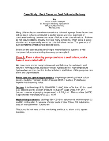
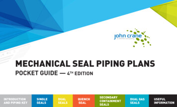
API 682 BEST PIPING PRACTICESSINGLE SEALS - PLAN 23 ILLUSTRATEDHigh Point Vent40mm/m / ½" per footMin. SlopeFlushInletNormallyOpenFlush Outlet ToHeat ExchangerShaftGland450-600 mm(18-24 inch)Note: The total length ofVerticalEquipment CW ShaftRot. ShownHorizontalEquipmentconnection piping between themechanical seal and the auxiliarysystem should not exceed 5m(16.4 ft).Flush Inlet To SealLow PointDrain ValveNote: Long radius bends shallbe used to minimize frictionlosses and elbows should beavoided. Elbows shown in sketchare for illustrative purpose only.
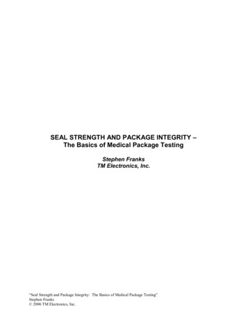
Note: Long radius bends shall be used tominimize friction losses and elbows shouldbe avoided. Elbows shown in sketch are forillustrative purpose only.Note: The total length of connection pipingbetween the mechanical seal and the auxiliarysystem should not exceed 5m (16.4 ft).HorizontalEquipment40mm/m /½" per foot Min. Slope1m36"Barrier OutletVerticalEquipmentShaftGlandCW ShaftRot. ShownBarrier InletDrain ValveLow Point Drain ValveBarrierInletAPI 682 BEST PIPING PRACTICESDUAL SEALS - PLAN 53A ILLUSTRATED
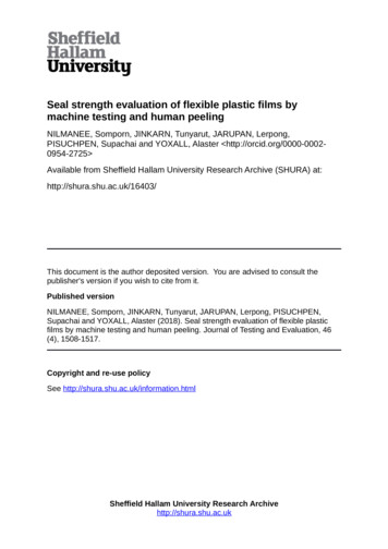
No external flushPLAN 01 Quench optionalInternal flush portingQuench/DrainQuenchDrainGland End View
SINGLE SEALSAdvantages: No product contamination and no external piping, which isadvantageous on highly viscous fluids at lower temperatures to minimize therisk of freezing that can occur with exposed piping.General: This flush plan should only be used for clean products as dirtyproducts can clog the internal line. Not recommended on vertical pumps.PLAN 01Description: Plan 01 is an internal recirculation from the pump dischargearea of the pump into the seal chamber, similar to a Plan 11 but with noexposed piping.
PLAN 02Optional heating/coolinginlet/outletLarge bore sealchamber isrecommended No flush - normal Vent/Flush(If req'd) plugged Quench optional Ensure sealchamber is fullyventedFlush, pluggedQuench/DrainFlush,pluggedVent ifrequiredQuenchDrainGland End View
SINGLE SEALSDescription: Plan 02 is a non-circulating flush plan where adequate vaporsuppression can be assured.General: Most commonly used on large bore pumps utilizing a cooling jacket.The use of a Plan 62 with a steam quench can also provide some additionalcooling on hot applications. Success on hot applications depends upon keepingthe cooling jacket clean which is prone to fouling.PLAN 02Advantages: Solids are not continually introduced into the seal chamber, noexternal hardware is required.
Quench optionalPLAN 03 Tapered bore sealchambers are selfventingLarge tapered boreseal chamber. Flowmodifiers may DrainGland End View
SINGLE SEALSDescription: Plan 03 is circulation between seal chamber and pump created bydesign of the seal chamber.General: Commonly used on ASME/ANSI or specialized ISO 3069 taperedbore seal chambers, without a throat bushing, for applications where thereis not significant heat generated by the seal or where solids may collect in atraditional seal chamber.PLAN 03Advantages: Circulation for cooling and venting of the seal is achieved by designof the seal chamber geometry or flow enhancement features.
Quench optionalOrificePLAN 11By-pass fromdischargeFlushQuench/Drain FlushQuenchDrainGland End View
SINGLE SEALSAdvantages: No product contamination and piping is simple.General: If the seal is set up with a distributed or extended flush, theeffectiveness of the system will be improved.Note: See John Crane Technical Report TRP-11-14/ENG for additionalinformation.PLAN 11Description: Plan 11 is the most common flush plan in use today. This plantakes fluid from the pump discharge (or from an intermediate stage) through anorifice(s) and directs it to the seal chamber to provide cooling and lubrication tothe seal faces.
Quench optionalStrainerPLAN 12By-pass rainQuenchDrainGland End View
SINGLE SEALSDescription: Plan 12 is similar to Plan 11, except that a strainer is added to theflush line.General: If the seal is set up with a distributed or extended flush, theeffectiveness of the system will be improved. This plan should be equipped witha differential pressure indicator or alarm to alert the user that the strainer isclogged.Note: API 682 4th edition comments “This plan has not been proven to achieve a3-year operating life.”Note: See John Crane Technical Report TRP-11-14/ENG for additionalinformation.PLAN 12Advantages: No product contamination and solids are removed from the flushstream keeping the seal clean.
Quench optionalOrificePLAN 13Returnto suctionFlush outletQuench/DrainFlushoutletQuenchDrainGland End View
SINGLE SEALSDescription: In a Plan 13 the flow exits the seal chamber and is routed back topump suction. Standard arrangement for vertical and high head pumps.General: Typically Plan 13 is used on vertical pumps since they have thedischarge at the top of the pump where the seal is located. Because of thedifference in flow patterns, Plan 13 is not as efficient in removing heat as aPlan 11 and thus requires a higher flow rate.Note: See John Crane Technical Report TRP-11-14/ENG for additionalinformation.PLAN 13Advantages: With a Plan 13 it is possible to control seal chamber pressure withproper sizing of the orifice and throat bushing clearance.
PLAN 14 Quench optionalOrificeBy-pass fromdischargeOrificeReturnto suctionFlush outletFlushoutletQuench/DrainFlush inletQuenchDrain Flush inletGland End View
SINGLE SEALSDescription: Plan 14 is a combination of Plans 11 and 13. Flush is taken off ofpump discharge, sent to the seal chamber, and piped back to pump suction.General: Often used on vertical pumps to provide adequate flow and vaporpressure margin independent of throat bushing design.Note: See John Crane Technical Report TRP-11-14/ENG for additionalinformation.PLAN 14Advantages: Cooling can be optimized with the flush directed at the seal faces.Plan 14 allows for automatic venting of the seal chamber.
Quench optionalPLAN 21OrificeHeat exchangerBy-pass fromdischargeCooling waterconnectionsFlushTIVent, pluggedFlush outletDrain DrainGland End View
SINGLE SEALSAdvantages: Process fluid cools and lubricates the seal, therefore no dilutionof process stream. Cooling improves lubricity and reduces the possibility ofvaporization in the seal chamber.General: Plan 21 is not a preferred plan, either by API or many users, due to thehigh heat load on the heat exchanger. Plan 23 is preferred.PLAN 21Description: Plan 21 is a cooled version of Plan 11. The product from pumpdischarge is directed through an orifice, then to a heat exchanger to lower thetemperature before being introduced into the seal chamber.
Quench optionalPLAN 22OrificeHeat exchangerVent, pluggedStrainerCooling waterconnectionsFlushTIFlush outletDrain DrainGland End View
SINGLE SEALSDescription: Plan 22 is a modified version of a Plan 21 with the addition of astrainer before the orifice.Disadvantage: Plan 22 should be used with caution as strainers can clog andresult in seal failure.General: If the seal is set up with a distributed or extended flush, the effectivenessof the system will be improved. This plan should be equipped with a differentialpressure indicator or alarm to alert the user that the strainer is clogged.NOTE: API 682 4th edition comments “This plan has not been proven to achieve a3-
Flush is taken off of pump discharge, sent to the seal chamber, and piped back to pump suction. Advantages: Cooling can be optimized with the flush directed at the seal faces. Plan 14 allows for automatic venting of the seal chamber. General: Often used on