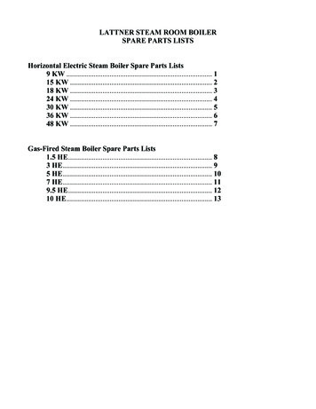
Transcription
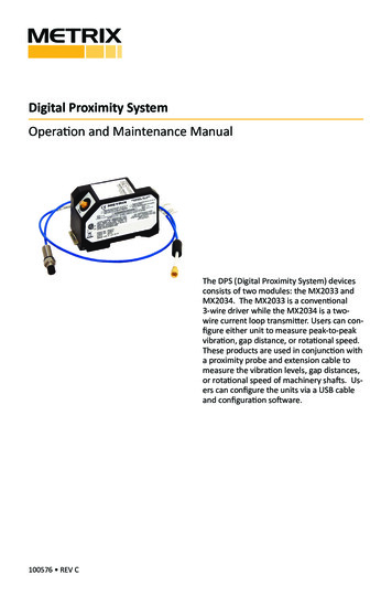
DEPARTMENTSCASE HISTORIESVibration Monitoring IdentifiesSteam Turbine Seal Rub Pankajkumar SharmaSenior Services Manager IndiaRegion Machinery Diagnostics ServicesPankajkumar.sharma@ge.comIn 2005, the Bently Nevada team entered intoMonitored Assetsa long term service agreement (sometimesThe machine of interest is a centrifugal compressorknown as Supporting Services Agreement, ordriven through a flexible disc pack coupling by aSSA) with a petrochemical plant in India. Scopeof work included monthly visits for machinerydiagnostics and regular optimization of data14-stage 30 MW steam turbine (Figure 1) with ratedrunning speed of 4068 rpm (maximum 4271 rpm).The turbine and compressor both have fluid-filmbearings, and both are instrumented with XY proximitycollected in the machinery management softwaretransducers for radial vibration monitoring, axial probes– which included both Data Manager* 2000 &for thrust position monitoring, and a Keyphasor*System 1* installations. The events describedtransducer for phase and speed measurements. Thein this article took place on a compressor unitmachine train is protected using a Bently Nevada 3300in one of the main plants at the facility.System, while Data Manager 2000 software facilitatesvibration condition monitoring and diagnostics.FIGURE 1:J ul . N o. Vol.
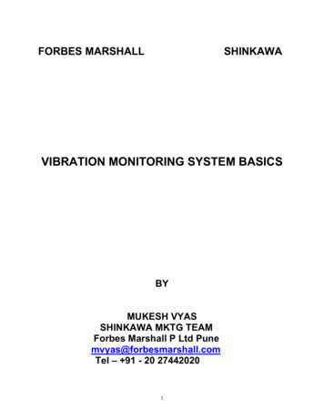
DEPARTMENTSCASE HISTORIESFIGURE 2: July-September 2007 trend of Direct (broadband) vibration amplitudes on steam turbine NDE bearing.FIGURE 3: August-September 2007 waterfall plot showing spectral components of the vibration excursions onturbine NDE bearing during August and September. Note: The 69 Hz peak corresponds to the machine runningspeed, which validates that it is 1X vibration.Event HistoryIn July and August, 2007, the steam turbine NDE bearingFrequency domain analysis showed thatstarted showing brief high vibration excursions on boththe vibration excursions were mainly due toprobes (Figure 2). Although peak amplitudes were lesssynchronous (1X) excitation (Figure 3).than the Alert setpoints, these vibration excursions startedbecoming more frequent in the month of September. Vo l . N o. J ul .
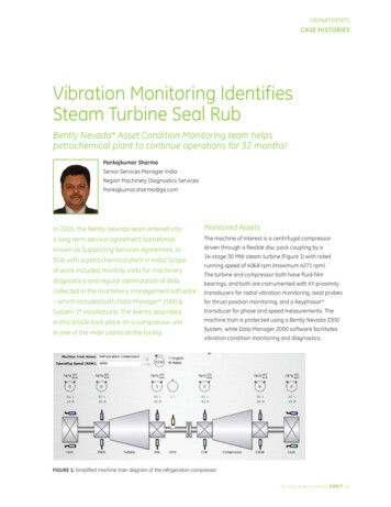
DEPARTMENTSCASE HISTORIESFIGURE 4: September 2007 ADRE polar plots showing widely varying phase angles forFIGURE 5: September 2007: ADRE plots show changes in orbit size and vibration phase(Keyphasor dot) indicating intermittent rotor bow symptoms.To study the event in more detail, we used the highthe phase changed significantly from one event toresolution trend capabilities of Data Manager 2000the next (Figure 4). These observations indicatedsoftware, and connected an ADRE* unit to collectthe possibility of an intermittent rotor thermal bow,additional data. Along with 1X vibration amplitudewith the added characteristic of a “hot spot” locationchanges, 1X phase changes were negligible during anythat did not remain constant. Orbit size and shapesingle event of elevated vibration amplitude. However,(Figure 5) confirmed the rotor bow due to a rub.J ul . N o. Vol.
DEPARTMENTSRECIP TIPSRub-Induced Thermal BowFigure 6 shows a local heating mechanism that cancause thermal bow of a rotor. Due to friction & impactforces caused by a rub, localized heating of the rotorcreates a hot spot at the point of contact between therotor and a stationary component of the machine. Whencombined with the rotor’s original heavy spot (residualunbalance), the “high spot” at the heated area producesa new effective unbalance vector and a new heavy spotresulting in a new phase angle for the 1X vibration. Ifthe location of the hot spot doesn’t change over a rubcycle, the thermal vector is repeatable and the resultantphase angle is constant. However, the amplitude andphase change due to new effective unbalance vector.With an intermittent rub, the hot spot – and its associatedthermal vector – disappear when the physical contactbetween the rotor and the stationary component iseliminated. The hot spot cools, the rotor bow subsides, andvibration amplitudes and vectors return to original valuesbased on residual unbalance, without the influence of athermal bow. However, if the root cause remains and therub reappears, causing a new hot spot with a differentlocation, the vibration excursion may happen again – witha completely different vector. This appeared to be whatwas happening during the observed events of 2007.Annular rub is another variety which can destroy themachine in a matter of hours when the rotor contactsstationary components such as the inner surface of asteam seal or bearing for a full 360 degrees. With thistype of rub, the orbit is typically very circular, since therotor is rolling all the way around the inner surfaceof the stationary component. If adequate lubricationexists between the rotor and the stationary component,precession of the rotor vibration will continue to beFIGURE 6: Changes in vibration amplitude (orbit size) and phase (Keyphasor dot location) can occurwhen a rub causes a hot spot that produces a thermal rotor bow. Vo l . N o. J ul .
DEPARTMENTSCASE HISTORIESforward (in the same direction as shaft rotation). But ifAdditionally, the staff planned ahead for correctiveinadequate lubrication exists, it produces a dry rub, whichmaintenance in case the compressor needed to beresults in reverse precession, and in its most extremeshut down before the next scheduled outage. Theyform, can destroy the machine in a matter of minutes.staged a spare turbine rotor and related spare partsNote: A rub is always a secondary effect that is produced when anothermalfunction causes the average or dynamic shaft centerline to betoo close to the limits of available clearance between rotating andstationary components. Excessive radial loads caused by problemssuch as misalignment can force the average shaft centerline toshift too close to the clearance limits, while high vibration causedby unbalance, instabilities or rotor bows can allow contact tooccur even if the average shaft centerline position is normal.for this contingency, and were standing by to takeaction at short notice if needed. Operations continuedas before, with occasional instances where vibrationamplitude briefly exceeded the Alert setpoint (Figure 7).Eventually, at two different times, vibration amplitudeexceeded the Danger setpoint and caused the machineData Evaluationto trip (20JUL2008 & 13AUG2009). One of these instancesAs discussed, the observed orbits were not circular,happened late on a Sunday evening. Immediatelyand observed precession was predominately forward.following the trip, the Bently Nevada Machinery DiagnosticCombined with the fact that the episodes of elevatedServices (MDS) Engineer remotely analyzed the datavibration were not continuous, these symptoms indicatedfrom Data Manager 2000 over a dial-up network.the presence of a light, intermittent rub. The changingphase angles corresponded to a classic shaft rubThe MDS Engineer verified that the steam turbine hadwith a wandering hot spot causing a thermal bow.tripped due to excessive high vibration during anotherbrief episode of rotor thermal bow, which was similar toVibration data pointed to a localized rub close towhat had been observed for several months. Plant staffbearing 1 (steam turbine NDE, the governor end ofallowed the rotor to cool and the bow to straighten bythe turbine). The most suspected locations wereoperating the machine train at slow-roll conditions. Afterthe bearing 1 oil seal – where accumulation andverifying that vectors were within acceptable values,hardening of lube oil in the labyrinth seal may havethey continued with a very cautious startup. Operationhad the chance to create hard coke deposits – and thecontinued under close observation by the plant conditionHP packing (front labyrinth seal of the casing itself),monitoring team and Bently Nevada MDS engineers.which is made of a very hard stainless steel alloy.The first occurrence of rub had been witnessed in theAction Planmonth of July, 2007 and the refrigeration unit wasSince the high vibration amplitudes were less than thesuccessfully run until March, 2010 with heightenedalert setpoint, and the intermittent events were of shortmonitoring. As 2010 progressed, the observedduration, plant staff decided to continue running thetime between the episodes of high vibration wascompressor while closely observing the data availableincreasing. It was apparent that there was a definitein the Data Manager 2000 software. They controlledtrend of small peaks appearing in clusters, buildingoperations to minimize changes in process conditionsup to the highest amplitude peak over a period ofin order to limit the occurrences of high vibration. Thisabout 6 to 8 days. Once past the high amplitudeallowed them to meet plant production requirements while peak, the vibration excursions would cease for amaintaining a heightened watch on compressor condition.few days and then gradually reappear (Figure 8).J ul . N o. Vol.
DEPARTMENTSCASE HISTORIESFIGURE 7: May 2008 trend shows persisting vibration excursions, occasionally crossing the Alert set point(yellow line, emphasized by a dashed line overlay at 100 microns pp).FIGURE 8: January-March 2010 trends show that vibration excursions continued, and that the period betweenepisodes of peak amplitude was increasing. Vo l . N o. J ul .
DEPARTMENTSCASE HISTORIESFIGURE 9: 11-13MAR2010 trend shows sudden vibration increase on steam turbine DE bearing.The ShutdownAlthough the plant engineers knew that they needed toperform an internal inspection of the steam turbine – andmost likely replace some damaged seal components –they were able to avoid shutting down the refrigerationunit for more than 32 months after the first occurrenceof the rub. They mitigated the risk of operation and builttheir confidence in managing the plant by continuing closeobservation of vibration condition monitoring data usingthe continuous data collection of the 3300 System and thediagnostic features of the Data Manager 2000 software.Everything was fine until 13MAR2010, when therewas a sudden increase in vibration on the turbineDE bearing (Figure 9). This vibration spike was verysudden, as observed in 4 second fast trends capturedduring a high vibration Alert event. Interestingly,no elevated vibration amplitudes were recordedon the steam turbine NDE bearing. Vibration risewas just 15 microns pp on the NDE bearing.At the same time as the sudden increase in vibrationoccurred, a sudden small (1 micron) shift in averageshaft centerline position was recorded at both theDE and the NDE bearings of the steam turbine.As we will see in the inspection results photos(Figure 12), this small but significant change wascaused by an interesting mechanical event Also, a significant shift in rotor precession occurredat the time of the elevated vibration. Figures 10& 11 show that the orbit shapes changed andthe forward and reverse vibration componentschanged – as shown in the full waterfall plots.J ul . N o. Vol.
DEPARTMENTSCASE HISTORIESFIGURE 10: Orbits and full waterfall for steam turbine NDE bearing. Reverse 1X frequency components dominated,and change in orbit shape indicated a change in radial loading caused by the increase in rub severity.FIGURE 11: Orbits and full waterfall for steam turbine DE bearing. Forward 1X frequency components dominated.As we will see in Figure 12, there was a very good mechanical cause for increased unbalance at the DE bearing endof the turbine rotor.t Vo l . N o. J ul .
DEPARTMENTSCASE HISTORIESThe DE bearings at both the compressor and the steamturbine experienced the maximum changes in amplitudesof vibration with corresponding 1X phase changes. TheseInspection ResultsRUPTURED TURBINE BLADEvibration changes at the DE bearings persisted. ChangesVisual inspection revealed that the machine couplingon the steam turbine NDE bearings were smaller and didwas intact but one of the steam turbine bladesnot persist. After the initial step changes, 1X vibrationhad ruptured at about 100 mm from the tip (overallamplitudes and phase angles at NDE bearings stabilized.blade is about 325 mm long). The unbalanced forcecaused by this “liberated” blade (Figure 12) explainsSynchronous Rotor Responsethe observed sudden step change in vibration.Synchronous or 1X vibration response is the resultantof both unbalance force and dynamic stiffness of theSTEAM SEAL COKINGrotor system. Changes in either one of them (or both)The cause of the intermittent light rub was identifiedcan cause changes in 1X amplitudes and phase.as formation of coke deposits on the NDE oil labyrinthSynchronous response motion (d) Unbalance ForceDynamic Stiffnessseal. Rubbing against the hard carbon depositswas observed to cause deeply scored grooves onthe corresponding rotor shaft area (Figure 13). TheA sudden change in 1X amplitudes, as was observedaffected area was about 100 mm wide and thein this event, can be caused by a sudden change ingrooves were up to 35 mm deep in the rotor shaft!unbalance force. Such changes can be caused bythe addition of mass (anything becoming loose andtrapped in the rotor) or removal of mass (typically bya blade failure on LP stages of the steam turbine).Damage to the coupling (such as a bolt that breaksand flies out) can also cause changes in 1X amplitudeon DE bearings of both compressor and turbine.Based on these possibilities, our MDS Engineerrecommended shutting down the compressor atthe earliest opportunity to inspect the coupling andthe steam turbine internals. Over the next few days,increasing vibration trends were noted, along withhigher than normal structural vibration in associatedpiping and supports. At this time, plant staff shutdown the refrigeration unit for planned inspectionand any required corrective maintenance.FIGURE 12: One blade had ruptured at the last row of the
Vibration Monitoring Identifies Steam Turbine Seal Rub In 2005, the Bently Nevada team entered into a long term service agreement (sometimes known as Supporting Services Agreement, or SSA) with a petrochemical plant in India. Scope of work included monthly visits for machinery diagnostics and regular optimization of dataFile Size: 1MBPage Count: 11