Transcription
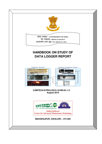
Hkkjr ljdkj &GOVERNMENT OF INDIAjsy ea ky;& MINISTRY OF RAILWAYS¼dk;kZy;hu iz;ksx gsrq½& (For official use only)HANDBOOK ON STUDY OFDATA LOGGER REPORTCAMTECH/S/PROJ/2015-16/HB-DL/1.0August 2015MAHARAJPUR, GWALIOR – 474 005
CONTENTSSr.DescriptionPage 10.11111.111.1.111.1.211.21213IntroductionFailure related to operationFailure related to Engg. DepartmentFailure related to Electrical DepartmentFailure related to Signalling DepartmentAbnormal incidencesData loggerAdvantage of Data loggerTechnical SpecificationOther SpecificationOperating conditionInputs of data loggerMain features of data loggerKey provision in softwareNMDL Software and data logger networkClassification of NMDL and Fault EntryNMDLFeaturesNetwork monitoring featuresSignalling monitoring featuresOnline Signalling Monitoring ArchitectureOn line FaultTrack Simulation and train chartingReports, Relay operation Graph, Fault reportExtra features of reportOff line simulation with featuresFeatures of Data analysisBackup facilityPower Supply Monitoring SystemFeaturesRequired primary settingOn line failure trouble shooting processCentral office application and multi monitor simulationInstallation practicesAddition featuresMaintenanceDaily check data logger by on duty ESMCheck LED position both side modemTesting and maintenance of power supplyData logger monitoring by JE/SSE/Signal/TelecomTrouble shootingDo’s and 41
Page 1 of 41DATA LOGGER1.INTRODUCTIONOn Indian Railways, for the safe movement of trains, signals have been providedon all stations. Traffic department controls the operations of these signals. Thefailure in operating a signal is made available to traffic department. Thisinformation is then conveyed to Signal Department.Mainly for signal failure, following are reasons :1.1Failure relating to operationi.ii.iii.iv.1.2Failure relating to Engineering Departmenti.ii.iii.1.3Wrong operationChoosing wrong sequence of operationsWrong reporting failureDelay in operating the signal gearsFailure due to creepingFailure due to distracted insulation of track circuit by rail fittings,Ballast resistance and water logging etc.Failure due to stock /switch rail fittings, packing, out of square relatedfailures.Failure relating to Electrical Departmenti.ii.iii.Low/ high voltageShort circuit due to traction return current stripNo electrical supplyCAMTECH/S/PROJ/HB-DL/15-16
Page 2 of 411.4Failure relating to Signalling Departmenti.ii.iii.iv.v.vi.Blown off circuit fuseFused signal bulbDue to change in parameters of track circuit/ Axle counter .Failure of power supply equipment due to which power is notavailable to the signal circuit.Intermittent failure in relay contacts or high resistance .Poor maintenance1.5 Abnormal incidencesi. Bursting of pointii. Derailment of trainiii. Train accidentiv. Passing of signal in RED i.e. danger aspectIf failure gets automatically set right:A. Measuring all parametersB. Operating the gearsC. Observing the gearsD. Doing detail investigation2. DATA LOGGERThe process of using a computer to collect data through sensor , analyze the data andsave the data is called data logging and the instrument used in this called data loggers.Data logger is microprocessor-based system, which logs the information about therelays, which are connected to the data logger . Data logger monitors and records allactivities and event in the signalling system of a railway station.Data logger acts like a “black box”, which can scan, store and process the data forgenerating various user-friendly reports. It is also knows as “event logger.”With the help of data logger and the feedback given by the staff, actual position ofsystem can be verified. Adjusted parameters can be viewed.It is a microprocessor based equipment and logs the events occurring in the signallingfunction of a yard through the energized contact of the relays.CAMTECH/S/PROJ/HB-DL/15-16
Page 3 of 41The logged information is conveyed in the form of “information packets” to thecomputer. The packets are sent in till the next data logger gives the acknowledgementof receipt of packet. The data can be sent either in single direction, BI-direction or in alldirection. A data logger has a capacity to store 1.7 lakhs events. When a large amountof data is received, the old data will be erased on first–in–first-out basis.Data logger can work as a single data logger for a particular RRI/PI.The individual data loggers of various stations can be interconnected throughnetworking technology. Due to networking feature, the data of remote terminal unitsor remote panel stations can be viewed. For away places where round the clock staff isavailable like S&T control/ rest room.2.1 Advantage of data loggerI. Real cause of failure can be identified. Staff can not hide the cause.II. Failure of intermittent nature can be identified in first attempt only. So staff timecan be saved as they observing such failure for its repetition for a long period.For major detention of failure many times staffs are advised to observe faultsduring round the clock.III. Enquiry is easy in case of unusual/ dispute case.IV. Failure restoration time can be reduced with the help available i.e. analog anddigital inputs.Also suitable program can be prepare to check failure in the relay logicof RRI/PI circuit on the basis of line sequence operation of relays for eachroute setting /cancellation. The programmed information is displayed at anypoint in the sequence failure, giving complete information of the circuit relay,its circuit diagram sheet number and concerned fuse particulars. Other failurelike panel failure due to button relay stuck up/auto relay stuck up and powersensing relay failure help can be prepared.CAMTECH/S/PROJ/HB-DL/15-16
Page 4 of 41V. Signalling system will be more reliable as many failures can be saved on checkingthe analog inputs and taking the corrective measure on time.VI. Timer setting is proper or not can be monitored. This monitoring can be done for4 types of settingsa) Timer setting for more than 120 sec.b) Timer setting for less than 90 sec.c) Timer setting for less than 120 sec.d) Timer setting for more than 90 sec.VII. Bobbing of signal/ track/ point/ crank handle - which cannot be seen by neckedeyes, is identified.VIII. Preventive/ needless maintenance can be done. Following problems can beidentified Point operation-sluggish, if point is taking more than 8-10 sec./ Loose packingby detecting the break of wkr1 relays.Point setting in more than one attempt than problem can be either due toslackness in the track or signalling fittings or insufficientvoltage for the point motor to operate.Analog voltages-parameter sensing to detect the variation of values beyondlower and upper limits of standard settings.Unusual reports which are very useful to analyze-late start of train, latelowering of signal, more time taken by the driver in section, wrong operation,more speed of train, bursting of points, signal passed at “on” etc.CAMTECH/S/PROJ/HB-DL/15-16
Page 5 of 412.2 Technical specifications of data loggerThe data logger has 32 bit motorola 68000 microprocessor.Seven segment display for displaying the current time in hh:mm:ss format.2x24 liquid crystal display (LCD) screen for displaying the status of Dgital/analog signals, time & temperature etc.3x4 numeric keyboard to carryout various functions by viewing necessaryparameters on LCD screen.LED’s to indicate the status of 512 digital input.A temperature sensor to measure the temperature inside the data logger0 for every 115 minutes. If temperature execs 40 c, it generates an alarm.Two sets of three 4- male fdc connectors are provided for power supply at thebackside of the data logger.Using eight 37 –pin male d-connectors,256 digital inputs are connectedinternally through internal stack cards.Each 37-pin d-connectors can cater up to 32 digital input. There are totally 9 communication ports available for connecting differentequipment to the data logger.To a computer for running nmrh software for single cataloger through a9- pin male d-connector.The communication port 2 & 3 are used to connect networking the data loggerswitch each other through a 25-pin female d-connector.The communication port 6,7, 8 & 9 are used for 20ma current loopcommunication through 9-pinmale d-connectors.A printer can be connected to data logger through a 25-pin femaled - connector to have a hard copy of all the events occurred.Two sets of controls are provided for connecting tele controls to the dataloggers with the help of 25-pin female d –connectors.The data loggers are interlined with the help of modems through two 9-pinmale d- connectors.Data logger can measure the temperature outside using a connector.Real time clock with internal battery backup & internal oscillator, data retentionup to 10 years.Internal buzzer for alarming during failures.External two relay contacts for remote buzzer.1 mega bytes of flash ram’s.CAMTECH/S/PROJ/HB-DL/15-16
Page 6 of 412.3 Other specificationsPower supply-( 12 /24 volts dc supply )For continuous operation of data logger a charger with battery is provided.Battery should 12v /40 ah and maintenance free.3. Operating conditions:0Temperature : 0-50 c Power : 230v ac 10% 47-67 HzConsumption : 2 watts max4. INPUTS TO DATA LOGGERA data logger records two types of inputs4.1 Digital4.2 Analog5. Main features of data logger Scanning of digital inputs Scanning of digital inputs after every 20 milli. seconds.I. Each input is optically isolated.II. Each scanner card can support 256 inputs. Every input requires a current of 10 ma.FIFO logic implemented for data being stored in the memory.III. Validity of each record should have its own identityIV. On switching on power, the processor conducts diagnosis of theentire processor viz.-I/O chips and other peripherals.CAMTECH/S/PROJ/HB-DL/15-16
Page 7 of 41V.After successful diagnosis, time is displayed on the seven segment in thefollowing format- hh:mm:ss ( hours, minutes and seconds)Vi.After scanning, the data is processed and various reports can generatedby data logger or data can be updated to the computer.VII.Now with the help of key board various functions as listed below can becarried out, by viewing the necessary parameters/ details in the LCDpanel . setting of time page display status of digital signal status of analog fault q printer / buzzer temperature display change of password6. Key provisions in softwareObjectives:To Receive & Process the raw data logged by the Data Logger & display the informationin user understandable format for Centralized Monitoring and Controlling of DataLogger NetworkTo provide user friendly tools, for appropriate decission making by analyzing thelogged data .CAMTECH/S/PROJ/HB-DL/15-16
Page 8 of 41Railway Data Acquisition System Softwares1. NMDL7. Network Monitoring2. Simulation8. COA3. Reports9. TIMS4. Multi Monitor Simulation10. Train Charting5. Fault Entry11. PMS6. Signalling Monitoring6.1 NMDL softwareTo get on line information sent by individual data loggers placed at differentstations of the network and to effectively manage the communication betweenthe networked data loggers.Purpose:1. To receive data from Data Logger network.2. To process the Data Logger wise data in sequence for Real Time Mimic of Station Layout Real Time Signalling System failure alarms To avail Remote monitor & control of assets like Data Loggers Relay Huts Modems To Log Data Logger wise data in Data Base.3. To analyze the Unusual occurances, for appropriate decission making.CAMTECH/S/PROJ/HB-DL/15-16
Page 9 of 41Data Logger NetworkCAMTECH/S/PROJ/HB-DL/15-16
Page 10 of 416.2 Classification of NMDL ModulesNMDL Modules have been classified as :1. Configuring Modules Fault Entry Fault Entry for Signaling Monitoring Track Editor2. Processing Modules NMDL3. Analysing Modules Reports Off Line Simulation4. Utility Modules Auto Back Up (Oracle) Extract DB VoltTimeP NMDL Test ProtocolCAMTECH/S/PROJ/HB-DL/15-16
Page 11 of 41Configuring Modules - Fault EntryCAMTECH/S/PROJ/HB-DL/15-16
Page 12 of 41Configuring Modules - Fault Entry for Signal MonitoringCAMTECH/S/PROJ/HB-DL/15-16
Page 13 of 416.3 Processing Modules - NMDL6.3.1 Features:1. Product Health Indication likea. SSI Healthb. Digital Stack Card Statusc. Nand Flash Healthd. Safety Point Health2. Network Monitoring System for easy Maintenance of Data loggerNetwork3. Signaling Monitoring Application4. On-line Asset-Failure Alarms5. On-line Yard Simulation6. Supports Oracle, Inter base data bases.7. This data can be useful in other applications likea. Train Chartingb. Train Information Management System8. Auto Time SynchronizationCAMTECH/S/PROJ/HB-DL/15-16
Page 14 of 416.3.2 Network Monitoring FeaturesA. Status display of Sub Systems and Failure Details.1. Modem Link Status2. Healthiness of data flow in each direction3. Data Logger / Relay Hut status4. FEP Status5. CMU and Server status6. LAN StatusB. Restoration of Network Failures from Central Location.1. Modem Reset2. Data Logger / RTU Time Setting3. Getting old data from data logger to central location4. Blocking of redundant data after restoration of data path after failureCAMTECH/S/PROJ/HB-DL/15-16
Page 15 of 416.3.3 Signaling Monitoring FeaturesI. Status display of Sub Systems and Failure Details.1. Relay Room Door Status2. SM Key Status3. Power Supply Status4. Data Logger, Relay Hut, LC Gate, IB status5. Modem Link Status6. Block Section Status7. Healthiness of data flow in each direction8. Equipment Failure Details9. Unacknowledged confirmed Fault Count10. Magnifier option11. FEP Status12. CMU and Server statusCAMTECH/S/PROJ/HB-DL/15-16
Page 16 of 41Signalling Monitoring Faults:CAMTECH/S/PROJ/HB-DL/15-16
Page 17 of 416.4 Online Signaling PROJ/HB-DL/15-16Online signalingclinet - 1Online signalingclinet - N
Page 18 of 416.4.1 On-line faultsTo expect the forthcoming problems due to the faults in signal operatingmechanism as well as to replace the damaged equipment. To identifying faults inthe station based on pre-fixed logic given by railways like :I.Blanking of signalsII.Fusing of signals lampsIII.TPR bobbingVI.Inter-slotting problemsV.Under wheel flashing of pointsVI.Point, track circuit, route failure ,emergency cancellation of routeVII.Timer not properly set for 120 seconds.VIII.Push button stuckIX.Point failure- sluggish operation, loose packing .6.4.2 Track simulationTo get the scenario of complete yard layout with the help of a simulated yardenvironment reflecting on line and offline status of various signals such as signalglowing, TPR occupation, track movement etc. This facility helps to know atremote end .I.Analyzing the real cause of failure/derailment in yard and status ofassociate gears/bursting of points.II. Need not to ask the field staff.III. Train speed can be calculated.IV. Real time of point and signals operation.V. Wrong operation/ intermittent failure.VI. Signal passing at danger.CAMTECH/S/PROJ/HB-DL/15-16
Page 19 of 41NMDLOnline Yard SimulationCAMTECH/S/PROJ/HB-DL/15-16
Page 20 of 41Processing Modules – NMDLTrain ChartingCAMTECH/S/PROJ/HB-DL/15-16
Page 21 of 41Processing Modules – NMDLExtra Features: Auto SMS of Asset Failure. Auto Mailing Facility of Asset-Failure Reports Display of real time line occupancy and signal status of yards in a sectionfor Controller. NMDL can act like an FEP and sends received data to a remote system throughE1 modems. Instant SMS.6.5 ReportsTo get the offline reports of the status of various relays operating in the panelstations with real time . To analyze the reports of routes, relays, log of entries,faults and analog graphs, life of various equipments etc.Analysing Modules - ReportsFeatures:1. Reportsa. Log of events Reporti. Digitalii. AnalogCAMTECH/S/PROJ/HB-DL/15-16
Page 22 of 41b. Relay Reportc. Relay Status Reportd. Digital Stack Cards Statuse. Analog Card Statusf. Chatteringg. Sequence Missh. Communication Reporti.Packet Informationj.Data logger Statesk. Relay Room Reportl.Faultsi. Detailed Reportii. Summary Reportiii. Summary Report with Time detailsiv. Occurance - Restoration detailsv. Category wise Reportvi. Safety Point Operation Report2. Graphsa. Relay Operationsb. Power Supply variationsc. Communicationd. DuplicationCAMTECH/S/PROJ/HB-DL/15-16
Page 23 of 41Analysing Modules – ReportsCAMTECH/S/PROJ/HB-DL/15-16
Page 24 of 41Analysing Modules – ReportsCAMTECH/S/PROJ/HB-DL/15-16
Page 25 of 41Analysing Modules – ReportsRelay operation graph :CAMTECH/S/PROJ/HB-DL/15-16
Page 26 of 41Analysing Modules – ReportsRelay operation graph :CAMTECH/S/PROJ/HB-DL/15-16
Page 27 of 41Analysing Modules – ReportsFault – ReportCAMTECH/S/PROJ/HB-DL/15-16
Page 28 of 41Analysing Modules – ReportsFault – ReportCAMTECH/S/PROJ/HB-DL/15-16
Page 29 of 41Analysing Modules – ReportsFault – Report SummaryCAMTECH/S/PROJ/HB-DL/15-16
Page 30 of 41Analysing Modules – ReportsFault – Report Summary With timeCAMTECH/S/PROJ/HB-DL/15-16
Page 31 of 41Analysing Modules – Reports6.5.1 Extra Features:1. Drill down mechanisma. Detailed Fault Report for selected Fault, from Summary Report .b. Log off events report for Relays / Channels involved in selected Faultoccurance .c. Simulation of Station Mimic for selected Fault occurance timings, fromDetailed Report .2. Seperate indications for high lighting Chattering, Digital Stack card fail in LogOff events report .CAMTECH/S/PROJ/HB-DL/15-16
Page 32 of 41Analysing Modules - Off Line SimulationCAMTECH/S/PROJ/HB-DL/15-16
Page 33 of 41Analysing Modules - Off Line Simulation6.5.2 Features: Route indication for Panel / Route Relay Interlocking mechanisms. Optional display of Route indication for Shunt signal. Off Line Faults displaying. Off Line Faults processing. Flashing of Signal, Point relays when they are not in required state. Simulation for multiple Data Loggers / Relay Huts in single Map. Overview of total map Displaying of Train Speed Relay Search option Recording of SimulationAnalysing Modules - Off Line Simulation:6.5.3 Features for Data Analysis: Continue and Stop options when simulating a station for selected time interval. Previous and Next options to control the process manully. First option to restart the simulation. Latest Relay Status Window to show the textual representation of a set oflatest relay operations. Zoom In and Zoom Out options . Simulation with Actual Time option to process each record with time gap thatoriginally exist between two relay operations. Simulation with Fixed Time option to process each record with fixed timeinterval. Speed Bar to manage the simulation speed (For Fixed Time option).CAMTECH/S/PROJ/HB-DL/15-16
Page 34 of 417. Backup facilityThis software which is in built in NMDL( network) management of data loggers) takesthe backup of data that is logged by data loggers automatically soon after the size ofdatabase exceeds its limit( as specified by user) and stores it in permanent storagedevices like CD or ZIP drives.Utility Modules - Auto Back Up (Oracle)1. Daily backupa. To move data from Main user to Back up user2. Periodical backupa. To save Back up user data as files8. Power Supply Monitoring System8.1 Features:1. Monitors, Stores the status of power supply to a central place.2. Gives bird's eye-view of all stations power & power equipment status at easymonitoring-reduces MTTR3. Long term data analysis of power supply & equipment status leads to actions forincrease of MTBF of power equipment.8.2 Required Primary Settings:1. NMDL PMS Application should run at CMU2. PMS Application receives data through LAN from NMDL System.So, the LANConnectivity should established between the systems.CAMTECH/S/PROJ/HB-DL/15-16
Page 35 of 418.3 On Failure-Trouble Shooting Process:1. Check whether PMS Defined NMDL Running in CMU or not.2. Check whether windows Firewall is in off state or not. (in both the systems).3. Verify the LAN connectivity between 2 Systems & Database connectivity withthe server.Power Supply MonitoringCAMTECH/S/PROJ/HB-DL/15-16
Page 36 of 419. COA-Central Office Application In Previous train departure and arrival timings at interchange stations andterminal stations are taken by COA from manual charting data of sectioncontrollers. On observing serious discrepancies in train departure and arrival timingsrecording by two adjacent division section controllers, Railway Board (CRB&ML)decided to take the train arrival and departure events from data loggers ofinterchange and terminal stations and post them to the COA server of CRIS .Processing Modules – NMDLMulti Monitor SimulationCAMTECH/S/PROJ/HB-DL/15-16
Page 37 of 4110.Installation practices1. Potential free contacts to be provided for all relays to be monitored.2. Potential free contacts shall be terminated as per specification enclosed.a. Analog voltages to be measured should be brought on to a stripconnector near the RTU with provisions for 10-mA fuse.3. Power supply to be provided nears the point where RTU will be placed.4. Communication wire [ quad ] terminated on to a strip connector near the RTU5. Intermediate termination should be rigid. This cable should be isolatedelectrically from other cable.6. No parallel path should be existing for this cable.7. Good earth terminal should be provided near the equipment.8. Communication cable-jelly filled 0.9-mm section copper conductor [0 12 2]paper quad, remain telecomm. unloaded cable pairs.9. Tested communication cable.10. Repeaters will be provided depending upon the necessity for communicationwhen the intermediate distance between location boxes or between locationbox and control room exceeds 4.0 km (cable distance) hence provision toinstall repeaters at these locations should be provided. UN-interruptible 230 V/110-V supply should be provided at repeaters.10.1 Additional FeatureInterface is to be provided for user-defined fault logic so that user ( Railway) canenter fault logic without necessitating help of supplier (Datalogger). Thisprovision is to be made in software at central monitoring unit. By doing this, theuser should be able to write length logic on his own choice.Ex. ( a ), (b ), (c ), (d ),(e ), (f )-------say up to 25 relays. The exist softwareshould be able to execute these user defined logic in the same way as doing forcompany defined fault logic.CAMTECH/S/PROJ/HB-DL/15-16
Page 38 of 4111. Maintenance11.1 Daily check of data logger by ESM on DUTY11.1.1 Check the LED position of both side modems.CD,REL,COM-LED should continue glow - Normal condition TD & RD LED shouldblink (flickering) - Normal conditiona. If LED’s status is different then reset the modem by pressing the resetbutton.b. If status of LED’s not changed then put off the modem supply, wait forfew minutes and put on the supply of modem.c. If LED’s are still not blinking then repeat the position of LED’s tosectional SI, TCI, SI-control and TCI test room.d. Check the Data logger supply. RED and GREEN LED should glow.e. Whenever such resetting required ESM must attend immediately.11.1.2 Testing and Maintenance of power supply,Battery and Batterychargera. Check the AC supply to the charger and record.b. Put off the charger.c. After 5 minute check the battery voltage and record, it should not be lessthen 13 V DC.d. Put on the charger.e. Record all measurement of individual battery voltage with sp. gravity,total battery voltage, charger voltage, charger battery voltage properly.Inform any abnormal position to sectional JE/SE (signal).CAMTECH/S/PROJ/HB-DL/15-16
Page 39 of 4111.2 Data /A. All sectional JE/SE (signal)/(Telecom) monitor the position of Datalogger should interact with JE/SE( signal) control.B. Sectional JE/SE (signal)/(Telecom) should check/ test and record themeasurement once in a month.C. Sectional JE/SE (telecomm.) must check the cable for noise if any withthe permission of SE(signal) control only.D. setermination, wiring etc.E. Never switch off the Data logger supply, if required take permission ofJE/SE(signal)/(telecomm).F. Sectional JE/SE/Sr.SE (signal)/(Telecom) will monitor the Data logger.CAMTECH/S/PROJ/HB-DL/15-16
Page 40 of 4112.Trouble shootingAll ModulesSr.no.1Error type1234521234567834Context/checking to bedoneRemedy for the errorDatabase Exceptions:NMDL NotCheck the communication port in the systemtaking data from Check the port and baud rateSet appropriate port and baud rateFEP/Data Logger details in communicationsetting in NMDLCheck communication cable between computer and FEP/Data LoggerCheck FEP/Data Logger, forReset the data logger/FEPhang conditionCheck whether Disk is fullRemove unnecessary files and makethe hard disk freeNMDL going toCheck the data. Gdb size andhang conditionreplace it with dataskel ,if its size islarge.Check the color setting of thesystem and set it to at least 16 bithigh colorCheck the RH setup whether theinformation is matching theconfiguration of data loggerClose the software and removecorresponding station. Sta file fromC:\Nmrh\Data folder.While closing the softwareCheck the NMDL software and loadthe compatible versionWhile opening the simulationCheck the simulation maps for anymapwrong entries. Reload thesimulation maps.Close the NMDL software and rerunit.Check the date format in controlpanel- regional setting. Dateformat must be DD/MM/YYYYrestart the computer.IncorrectWhile loading mapsCheck the color setting forparameterminimum 16 bit high color problemmay be with displayNMDL is alreadyRestart the computer and runRunningNMDLCAMTECH/S/PROJ/HB-DL/15-16
Page 41 of 4113. DO’S AND DON’TSr.no.DO’SDON’TS1Install the CMU in a Dust free andcool environment.Do not open Floppy’s/ CDs in the CMUwithout confirming that they are Virusfree.2Please assure that the system isrunning, with the NMDL software ,round the clock.Do not use the CMU for other softwarelike Signal failures entry / Signal incidencesoftware/ Auto CAD etc as the systemsetting required for NMDL Modules maybe disturbed.3Assure from time to time that thesystem has enough free space in the‘c’ DriveDo not install Games/Screen savers / wallpapers etc they may occupy maximumRAM , disturbing the proper working ofNMDL Modules.4Regularly at least once in 3 months, takes a copy of the previous 3months database in a CD.Do not Shutdown the system withoutproper close of NMDL and otherModules.CAMTECH/S/PROJ/HB-DL/15-16
2 Data logger 2-3 2.1 Advantage of Data logger 3-4 2.2 Technical Specification 5 2.3 Other Specification 6 3 Operating condition 6 4 Inputs of data logger 6 5 Main features of data logger 6-7 6 Key provision in software 7-8 6.1 NMDL Software and data logger network 8-9 6.2 Classification of NMDL and Fault Entry 10-12

