Transcription
MECHANICAL SEALPIPING PLANSPocket Guide
INDEXIntroductionSymbols . . . . . . . . . . . . . . . . . . . . . . . . . . . 4Color Key. . . . . . . . . . . . . . . . . . . . . . . . . . . 5Equipment Alignment . . . . . . . . . . . . . . . . . . . . 6Seal Chamber Preparation. . . . . . . . . . . . . . . . . . 8Installation and Operation Best Practices and Notes . . . . 9Seal Reservoir Systems. . . . . . . . . . . . . . . . . . . 10Seal Cooler Layout . . . . . . . . . . . . . . . . . . . . . 11Piping Plan Diagrams & NotesPROCESS SIDE12Plan 01. . . . . . . . . . . . . . . . . . . . . . . . . . . 12Plan 02. . . . . . . . . . . . . . . . . . . . . . . . . . . 14Plan 03. . . . . . . . . . . . . . . . . . . . . . . . . . . 16Plan 11. . . . . . . . . . . . . . . . . . . . . . . . . . . 18Plan 12. . . . . . . . . . . . . . . . . . . . . . . . . . . 20Plan 13. . . . . . . . . . . . . . . . . . . . . . . . . . . 22Plan 14. . . . . . . . . . . . . . . . . . . . . . . . . . . 24Plan 21. . . . . . . . . . . . . . . . . . . . . . . . . . . 26Plan 22. . . . . . . . . . . . . . . . . . . . . . . . . . . 28Plan 23. . . . . . . . . . . . . . . . . . . . . . . . . . . 30Plan 31. . . . . . . . . . . . . . . . . . . . . . . . . . . 32Plan 32. . . . . . . . . . . . . . . . . . . . . . . . . . . 34Plan 41. . . . . . . . . . . . . . . . . . . . . . . . . . . 36
BETWEEN SEALS38Plan 52. . . . . . . . . . . . . . . . . . . . . . . . . . . 38Plan 53A . . . . . . . . . . . . . . . . . . . . . . . . . . 40Plan 53B. . . . . . . . . . . . . . . . . . . . . . . . . . 42Plan 53C. . . . . . . . . . . . . . . . . . . . . . . . . . 44Plan 54. . . . . . . . . . . . . . . . . . . . . . . . . . . 46Plan 55. . . . . . . . . . . . . . . . . . . . . . . . . . . 48Plan 71. . . . . . . . . . . . . . . . . . . . . . . . . . . 50Plan 72. . . . . . . . . . . . . . . . . . . . . . . . . . . 52Plan 74. . . . . . . . . . . . . . . . . . . . . . . . . . . 54ATMOSPHERIC SIDE56Plan 51. . . . . . . . . . . . . . . . . . . . . . . . . . . 56Plan 61. . . . . . . . . . . . . . . . . . . . . . . . . . . 58Plan 62. . . . . . . . . . . . . . . . . . . . . . . . . . . 60Plan 65A . . . . . . . . . . . . . . . . . . . . . . . . . . 62Plan 65B. . . . . . . . . . . . . . . . . . . . . . . . . . 64Plan 66A . . . . . . . . . . . . . . . . . . . . . . . . . . 66Plan 66B. . . . . . . . . . . . . . . . . . . . . . . . . . 68Plan 75. . . . . . . . . . . . . . . . . . . . . . . . . . . 70Plan 76. . . . . . . . . . . . . . . . . . . . . . . . . . . 72GENERAL LAYOUTSSUPPLEMENTAL INFORMATION76General Statement of Terms and DataIncluded in this Booklet. . . . . . . . . . . . . . . . . . 76Temperature Ratings for Secondary Sealing Elements. . . 77Gland Bolt Torque Ratings. . . . . . . . . . . . . . . . . 78Cup Point Set Screw Torque Ratings. . . . . . . . . . . . 79Recommended Lubricant Selection for Seal Installation. . 80Buffer/Barrier Fluid Guidelines. . . . . . . . . . . . . . . 81Buffer/Barrier Fluids. . . . . . . . . . . . . . . . . . . . 82Single Stage, Single Suction, Overhung Process Pumps. . 86Single Stage, Double Suction Pumps. . . . . . . . . . . . 87Two Stage Horizontal Pumps. . . . . . . . . . . . . . . . 88Multistage Horizontal Pumps. . . . . . . . . . . . . . . . 89Vertical Multistage Pumps. . . . . . . . . . . . . . . . . 90Commonly Used Unit Conversions . . . . . . . . . . . . . 9174Plan 99. . . . . . . . . . . . . . . . . . . . . . . . . . . 743
SymbolsCooler, tube in shellLevel transmitter with local indicatorCooler, finned tubingBladder accumulatorCyclone separatorPiston accumulatorDifferential pressure transmitter with localindicatorPressure gaugeFilterPressure switchFlow indicatorPressure transmitter with local indicatorFlow orificeStrainerFlow transmitter with local indicatorTemperature indicator
Symbols, cont.Valve, normally openColor KeyCool/Clean Fluid Pump MediumLeakageValve, normally closedContaminated FluidValve, checkHot FluidValve, needleHot, Contaminated FluidValve, pressure controlQuench FluidValve, pressure reliefBarrier/Buffer FluidSolids5
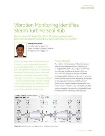
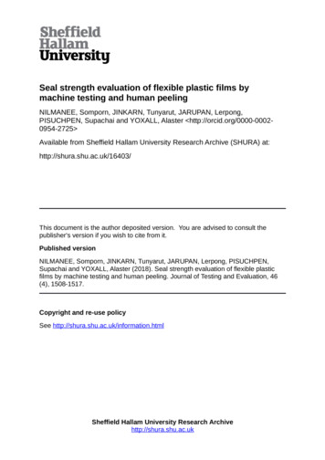
Equipment AlignmentInstallation, Operation & Maintenance GuideInstallation, Operation & MaintenanceStyleGuide79Style 79VERIFICATIONVERIFICATIONSuccessful operation of a Style 79 seal is contingent on conforming equipment dimensions and alignment.FIG. 1: ShaftFIG. 2:FitFIG. 3:Bearing FrameandPerpendicularityVerify the utatoStyle79 seal is ignment.Verify the following prior to continuing:Figure 1: Shaft RunoutFigure1: Shaft RunoutFIG. 4: Axial Shaft MovementFIG. 5: Seal Chamber Bore ConcentricityFigure 2: Bearing FitFigure 2: Bearing FitFigure 4: Axial ShaftFigureMovement4: Axial ShaftMovementFigure 5: Seal ChamberFigureSeal ChamberBore5:ConcentricityBore ConcentricityMaximum Alignment Variation (TIR)Figure 3: Bearing FrameFigure 3: Bearing FramePerpendicularityFIG. 6: SealPerpendicularityChamber Face SquarenessFigure 6: Seal ChamberFigureSeal ChamberFace6:SquarenessFace Squareness
Maximum Alignment Variation (TIR)FIG. 1Radial shaft movement (shaft runout)0.0015–0.003 in.FIG. 2Radial bearing fit0.002–0.003 in.FIG. 3Bearing frame perpendicularity0.0005 in./in.FIG. 4Axial shaft movement (end play)0.002 in.FIG. 5Seal chamber bore concentricity0.005 in.FIG. 6Seal chamber face squareness0.0005 in./in.For proper function and satisfactory operationof the seal it is imperative that connections,dimensions, finishes, and alignments are allacceptable based on the specified design. Ifmeasured values exceed the values given above,adjust the equipment to meet the specificationsbefore installing the seal. These values are generalguidelines and the pump OEM should be used toverify acceptable values whenever possible.7
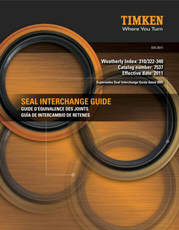
Seal Chamber PreparationSealing surfaces of the shaft, sleeve, bore, and seal chamber face must have a surface finish limit of 63 Ra-µin.For ease of installation, the leading edge of the shaft or sleeve should be chamfered as shown and all partsshould be deburred.(A) SLEEVE OD(B) BORE ID63.030 MIN. x 30 6363
Installation and Operation Best Practices and NotesTubing shall have a minimum diameter of 1/2 in. [13 mm] for shafts 2-1/2 in.[64 mm] or smaller. Tubing shall have a minimum diameter of 3/4 in. [19 mm]diameter for shafts 2-1/2 in. [64 mm] or larger.To minimize friction losses: Use long, smooth radius bends Use larger tubing whenever possible Use rigid tubing whenever possibleUse thread sealant instead of thread tape; thread tape can break apart anddamage the seal.IMPORTANT PLAN NOTES:All recirculation from discharge to lowerpressure regions will result in some lossof pump efficiency.For all single or dual unpressurizedseals, the product in the pump mustbe a good face lubricant for successfulseal performance.Minimize use of 90 elbows, 45 elbows are preferred.Use continuously rising lines at a minimum slope of 0.5 in./ft. [42 mm/m]. Thereshould be no relative high points that may result in trapped air in the tubing.Insulate hot lines as necessary for safety of personnel.9
Piping Practices for Seal Support Reservoir Systems Reservoir should have aminimum 3 gallon [11.4 L]volume for shafts less than2-1/2 in. [64 mm]. Reservoirshould have a minimum5 gallon [18.9 L] volume forshafts 2-1/2 in. [64 mm]or larger. The reservoir normal liquidlevel (centerline of sight glass)should be 36 in. [1 m] abovegland centerline. Reservoir should be located asclose to the pump as possible(within 36 in. [1 m] radius)while still leaving room foroperation and maintenance. Do not mount the reservoirdirectly above the pump.
Seal Cooler Layout and Best Practices The seal cooler should be mounted 18–24 in.[450–600 mm] above the gland centerline.VENT Cooler should be located as close to thepump as possible (within 36 in. [1 m]radius) while still leaving room for operationand maintenance.1 Do not mount the cooler directly abovethe pump.2 36 in.[1 m]COOLER CONNECTIONSTO SEALFROM SEAL1COOLING WATER IN2 COOLING WATER OUT118–24 in.[450–600 mm]2FLUSH OUTFLUSH INHORIZONTALPUMPVERTICALPUMPDRAIN11
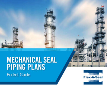
PLAN 0112Internal recirculation from pump discharge to the seal chamber.GLAND ENDVIEW
PLAN 01Application Notes: Used with fluids which are at risk of freezing, thickening,or solidifying in external piping.Seal Style Shown: SMSAdvantages: Same concept as Plan 11, without the external piping. Raises the seal chamber pressure. Vents the seal chamber during flooding of horizontal pumps.Disadvantages: The seal chamber is not self-venting in vertical applications. May only be used with clean fluids. The flush is not usually directed right at the faces but may come inover the seal head.PLAN 0113
PLAN 0214Dead-ended seal chamber with no recirculation of fluid and optionalcooling/heating jacket.GLAND ENDVIEW
PLAN 02Application Notes: Used in low speed applications with low seal chamberpressures where control of the seal chamber temperatureis desired. Common in the chemical industry. Cooling or heating jacket may be used to control the sealchamber temperature. Cooling jacket is recommendedfor narrow seal chambers. Chamber must be fully vented prior to pump startup. Flush port is plugged.PLAN 02Seal Style Shown: RBAdvantages: No external hardware or piping to the seal. Pump efficiency is unaffected. Solids are not reintroduced to the seal area.Disadvantages: Cooling jackets are prone to fouling in high temperature applications. Not applicable for vertical pumps (if supplied with a cylindrical bore).15
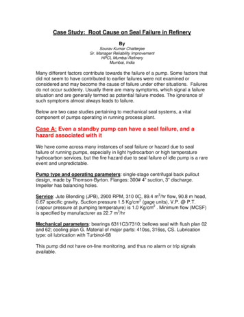
PLAN 0316Open-ended or tapered seal chamber.GLAND ENDVIEW
PLAN 03Seal Style Shown: FHDSApplication Notes: Circulation between the pump and seal chamber isAdvantages: Provides cooling for the seal without use of any external hardware ordriven by the geometry or flow enhancement features inthe seal chamber. Used in applications where solids would collect in atraditional cylindrical seal chamber. Flush port is plugged.piping. Vents air or vapors from the seal chamber in horizontal pumps. No throat bushing.Disadvantages: Control of the seal chamber environment is severely limited. The seal chamber is not self-venting in vertical applications. May not be recommended in applications with high seal chamberpressures and/or temperatures.PLAN 0317
PLAN 1118Recirculation from pump discharge through a flow control orifice tothe seal chamber.FLUSHGLAND ENDVIEW
PLAN 11Application Notes: Default seal flush plan for all Arrangement 1 and 2seals. Fluid flows from the seal chamber back into the processstream. Important to determine the required flush flow rate(especially for high-head applications) and selectproper orifice and throat bushing dimensions to assureadequate flow. Can be used without a flow control orifice for some lowSeal Style Shown: SMSAdvantages: Provides cooling for the seal. Vents air or vapors from the seal chamber in horizontal pumps. Applicable for all general duties with sufficient pressure differential.Disadvantages: Polymerizing fluids can cause clogging of the orifice and piping. Do not use with fluids which are at risk of freezing, thickening, orsolidifying in external piping.differential head or high viscosity applications.PLAN 1119
PLAN 1220Recirculation from pump discharge through a strainer and flow controlorifice to the seal chamber.FLUSHGLAND ENDVIEW
PLAN 12Application Notes: Similar to Plan 11, with the addition of a strainer beforethe orifice for removing occasional particles from slightlycontaminated fluids. A flow indicator, differential pressure indicator, or alarmis recommended to indicate strainer malfunction.Seal Style Shown: SMSAdvantages: Solids are removed from the flush stream, thus keeping the seal clean. Vents air or vapors from the seal chamber in horizontal pumps.Disadvantages: Strainers are not commonly recommended because blockage of thestrainer can cause seal failure. Product in the pump must be a good face lubricant. Typically does not achieve a three-year operating life.PLAN 1221
PLAN 1322Recirculation from the seal chamber through aflow control orifice to pump suction.FLUSHGLAND ENDVIEW
PLAN 13Application Notes: Standard flush plan selection for most vertical turbinepumps (except vertical in-line pumps). Flow control orifice can be omitted depending on therequired flush flow rate. Helps to reduce the stuffing box or seal chamberpressure. Can also be used for high head horizontal pumps wherePlan 11 cannot be used (i.e. low pressure differentialbetween seal chamber and pump discharge).PLAN 13Seal Style Shown: SMSAdvantages: Vents air or vapors from the seal chamber in vertical pumps. Applicable for all general dut
Circulation between the pump and seal chamber is driven by the geometry or flow enhancement features in the seal chamber . Used in applications where solids would collect in a traditional cylindrical seal chamber . Flush port is plugged . Advantages: Provides cooling for the seal without use of any external hardware or piping .