Transcription
Mechanical SealPiping PlansCompanion BookletSingle SealsDual SealsQuench SealsSecond. Cont.Dual Gas
IntroductionA primary factor in achieving highly reliable,effective sealing performance is to createthe best fluid environment around theseal. Selection of the right piping planand associated fluid control equipmentrequires a knowledge and understanding of the seal design and arrangement,fluids in which they operate, and of therotating equipment. Providing clean, coolface lubrication, effective heat removal,personnel and environmental safety, leakage management and controlling systemcosts are among the specific factors thatmust be considered. API has establishedstandardized piping plans for seals thatprovide industry guidelines for various sealarrangements, fluids and control equipment. The following pages illustrate anddescribe features of these plans as anaid to help you determine what supportsystem requirements will maximize theperformance reliability of your fluid handling rotating equipment application.
API 682/ISO 21049 standards havedefault (required) connections and connection symbols for seal chamber andgland plate connections based upon theseal configuration. It is recommendedthat the latest edition of these standardsbe reviewed for up-to-date requirements,when these standards are mandatedfor a piece of rotating equipment. Theintent of this booklet is to illustrate thecommon connections that are utilized forthe various piping plans, regardless ofthe equipment type, and therefore usegeneric names for connections. The enduser and/or equipment manufacturer mayhave specific requirements that dictatewhat connections are to be supplied andhow they are to be labeled.In the piping plans illustrated, the “Flush”connection noted for the inboard seal of adual seal may originate from a number ofsuitable sources. For example, the “Flush”for piping plans 11/75 or 32/75 maybe the product (Plan 11) or an externalsource (Plan 32).API682/ISO21049 General Comments
Piping Plan DescriptionPlan 01 Single Seals - Internal FlushPlan 02 Single Seals - No Flush, Large Open BorePlan 11 Single Seals - By-Pass From Discharge With OrificePlan 12 Single Seals - By-Pass From Discharge With Filter & OrificePlan 13 Single Seals - Flush Thru Seal Chamber Thru Orifice To SuctionPlan 14 Single Seals - By-Pass From Discharge Thru Seal Chamber Back To SuctionPlan 21 Single Seals - By-Pass From Discharge Thru Orifice & Heat ExchangerPlan 23 Single Seals - Closed Loop Circulation Thru Heat ExchangerPlan 31 Single Seals - By-Pass From Discharge Thru Orifice & Abrasive SeparatorPlan 32 Single Seals - External Flush Source To SealPlan 41 Single Seals - By-Pass From Discharge Thru Abrasive Separator & Heat ExchangerPlan 52 Dual Seals, Unpressurized - External Reservoir Unpressurized Liquid Buffer
Plan 53A Dual Seals, Pressurized - External Reservoir Pressurized Liquid BarrierPlan 53B Dual Seals, Pressurized - Liquid Barrier Thru Heat Exchanger & Pressurized By AccumulatorPlan 53C Dual Seals, Pressurized - Liquid Barrier Thru Heat Exchanger With Differential Tracking.Piston AccumulatorPlan 54 Dual Seals, Pressurized - External Pressurized Barrier System/SourcePlan 62 Quench Seals - External Quench On Atmospheric Side Of SealPlan 65 Single Seals - External Leakage Detection ReservoirPlan 72 Secondary Containment Seals - Low Pressure Buffer Gas Injected To Outer Seal CavityPlan 74 Dual Gas Seals - Pressurized Dual Gas Seal Thru Conditioning PanelPlan 75 Secondary Containment Seals - Secondary Cont. Seal With Leakage Collection ReservoirPlan 76 Secondary Containment Seals - Secondary Cont. Seal Vented To Flare Or Collection SystemPiping Plan Description
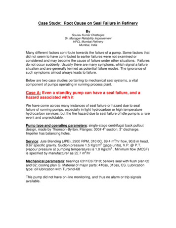
Plan 01 Single SealsDescription: Plan 01 is an internal recirculation from the pump discharge area ofthe pump into the seal chamber, similar toa Plan 11 but with no exposed piping.Advantages: No product contaminationand no external piping. Advantageous onhighly viscous fluids at lower temperaturesto minimize the risk of freezing that canoccur with exposed piping arrangements.General: This flush plan should only beused for clean products as dirty productscan clog the internal line. Not recommended on vertical pumps.
Vent PluggedInternal Flush PortingDrainGland End ViewVent PluggedDrainGlandEnd ViewVent (If Req’d.) PluggedNo External FlushC Quench OptionalCCPlan 01 Single Seals
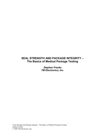
Plan 02 Single SealsDescription: Plan 02 is a non-circulat-General: Ideal with large bore/tapereding flush plan recommended only whereadequate vapor suppression can beassured.bore ANSI/ASME B73.1 or ISO 3069Type “C” seal chambers or with hot process pumps utilizing a cooling jacket. Onthe latter services, a Plan 62 with steamquench can also provide some additionalcooling.Advantages: Solids are not continuallyintroduced into the seal chamber, noexternal hardware is required, and naturalventing occurs when used with a taperedbore seal chamber.
Heating/CoolingInlet/OutletVent PluggedLarge Bore Open ThroatOr Taper Bore Box IsRecommendedDrainGland End ViewVent PluggedDrainGlandEnd ViewNo FlushVent (If Req’d.) PluggedC Quench OptionalC Ensure Seal ChamberIs Fully VentedCCPlan 02 Single Seals
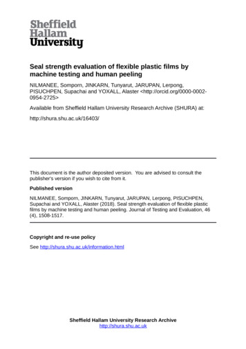
Plan 11 Single SealsDescription: Plan 11 is the most com-Advantages: No product contaminationmon flush plan in use today. This plantakes fluid from the pump discharge (orfrom an intermediate stage) through anorifice(s) and directs it to the seal chamber to provide cooling and lubrication tothe seal faces.and piping is simple.General: If the seal is setup with a distributed or extended flush, the effectivenessof the system will be improved.
OrificeFlushBy-Pass FromDischargeDrainGland End ViewFlushDrainGlandEnd ViewCPlan 11 Single SealsQuench Optional
Plan 12 Single SealsDescription: Plan 12 is similar to PlanGeneral: If the seal is setup with a dis-11, except that a strainer or filter is addedto the flush line.tributed or extended flush, the effectiveness of the system will be improved. Thisplan should be equipped with a differentialpressure indicator or alarm to alert theuser that the filter or strainer is clogged.Advantages: No product contaminationand solids are removed from the flushstream keeping the seal clean.
FlushStrainer Or FilterBy-Pass FromDischargeOrificeCleanoutTrapDrainGland End ViewFlushDrainGlandEnd ViewCPlan 12 Single SealsQuench Optional
Plan 13 Single SealsDescription: In a Plan 13, the flow exitsGeneral: Typically Plan 13 is used onthe seal chamber through an orifice andis routed back to pump suction.vertical turbine pumps since they havethe discharge at the top of the pumpwhere the seal is located. Because of thedifference in flow patterns, Plan 13 is notas efficient in removing heat as a Plan 11and thus requires a higher flow rate.Advantages: With a Plan 13, it is possible to increase or decrease seal chamberpressure with proper sizing of the orificeand throat bushing clearance.
OrificeReturn ToSuctionFlush OutletDrainGland End ViewFlush OutletDrainGlandEnd ViewCPlan 13 Single SealsQuench Optional
Plan 14 Single SealsDescription: Plan 14 is a combinationof Plans 11 and 13. Flush is taken off ofpump discharge, sent to the seal chamber,and piped back to pump suction.Advantages: Cooling can be optimizedwith the flush directed at the seal faces.Plan allows for automatic venting of theseal chamber.General: Often used on vertical pumpsto provide adequate flow and vaporpressure margin independent of throatbushing design.
Flush OutletOrificeBy-Pass FromDischargeOrificeReturn ToSuctionFlushOutletDrainFlush InletGland End ViewDrainFlush Inlet(Alt. into Gland)GlandEnd ViewCPlan 14 Single SealsQuench Optional
Plan 21 Single SealsDescription: Plan 21 is a cooled version of Plan 11. The product from pumpdischarge is directed through an orifice,then to a heat exchanger to lower thetemperature before being introduced intothe seal chamber.Advantages: Process fluid cools andlubricates the seal, therefore no dilution ofprocess stream. Cooling improves lubricityand reduces the possibility of vaporizationin the seal chamber.General: Plan 21 is not a preferred plan,either by API or many users, due to thehigh heat load put on the heat exchanger.A Plan 23 is preferred.
OrificeVent, NormallyClosedBy-Pass FromDischargeHeat ExchangerVent, NormallyClosedCooling WaterConnectionsFlushDrain, Norm. ClosedTemperatureIndicatorFlushDrainGlandEnd ViewPlan 21 Single SealsDrainGland End ViewCQuench Optional
Plan 23 Single SealsDescription: Plan 23 is a closed loopGeneral: Preferred plan for hot applica-system using a pumping ring to circulateproduct through a heat exchanger andback to the seal chamber.tions. Close clearance throat bushing isrecommended to reduce mixing of hotproduct with cooler closed loop systemfluid.Advantages: More efficient than a Plan21 and less chance of heat exchangerfouling. Reduced temperature improveslubricity and improves vapor pressuremargin.
Vent, NormallyClosedFlush Outlet(Alt. fromGland Conn.)Heat ExchangerCooling Water Vent,Normally ClosedFlush OutletShown For CWShaft RotationCooling WaterConnectionsCooling Water Drain,Norm. ClosedFlush InletPumpingRingTemperatureIndicatorDrainGlandEnd ViewPlan 23 Single SealsDrainFlush InletGland End ViewCQuench Optional
Plan 31 Single SealsDescription: Plan 31 is a variation ofPlan 11, where an abrasive separator isadded to the flush line. In this plan, theproduct is introduced to the abrasiveseparator from the discharge of the pump,clean flush is piped from the separator tothe seal chamber and solids are returnedto the pump suction.Advantages: Unlike a strainer or filter,the abrasive separator does not requirecleaning. Solids are removed from theflush stream keeping the seal clean.General: This plan should be used forservices containing solids that have aspecific gravity at least twice that of theprocess fluid. Typically the separatorrequires a minimum pressure differentialof 15 psi to operate properly.Note: A abrasive separator is subject towear and must be maintained regularly toensure efficient operation.
ycloneSeparatorOrifice(optional)FlushDrainGlandEnd ViewPlan 31 Single SealsDrainGland End ViewCQuench Optional
Plan 32 Single SealsDescription: Plan 32 uses a flushGeneral: When an outside flush sourcestream brought in from an externalsource to the seal. This plan is almostalways used in conjunction with a closeclearance throat bushing.is used, concerns regarding product dilutionand/or economics must be consideredby the user. Source pressure must bemaintained a minimum of 15 psig abovemaximum seal chamber pressure.Advantages: The external flush fluid,when selected properly, can result invastly extended seal life.
Flow Indicator (Optional)Flow Control ValveValve,Normally leExternal Flush SourceFlushFlushClean OutTrapCheck ValveTemperatureIndicator (Optional)CloseClearanceBushingDrainGlandEnd ViewPlan 32 Single SealsDrainGland End ViewCQuench Optional
Plan 41 Single SealsDescription: Plan 41 is a combination ofGeneral: Plan 41 is typically used on hotPlan 21 and Plan 31. In Plan 41, productfrom pump discharge is first put throughan abrasive separator and then to theheat exchanger before being introducedto the seal chamber.services with solids; however, dependingon the temperature of the process, operating costs can be high. This plan shouldbe used for services containing solids thathave a specific gravity at least twice thatof the process fluid. Typically the separatorrequires a minimum pressure differential of15 psi to operate properly.Advantages: Solids are removed andproduct temperature is reduced to enhance the seal’s environment.
Abrasive/Cyclone SeparatorVent, NormallyClosedHeat ExchangerBy-PassFromDischargeCooling WaterConnectionsFlushDrain, Norm. nDrainGland End ViewGlandEnd ViewPlan 41 Single SealsCQuench Optional
Plan 52 Dual Seals, UnpressurizedDescription: Plan 52 uses an externalreservoir to provide buffer fluid for theouter seal of an unpressurized dual sealarrangement.Advantages: In comparison to singleseals, dual unpressurized seals canprovide reduced net leakage rates as wellas redundancy in the event of a primaryseal failure.General: Cooling coils in the reservoirare available for removing heat from thebuffer fluid. Plan 52 is often used whereprocess fluid contamination can not betolerated.
Note: Tangential porting is unidirectional. Gland is illustrated forCCW shaft rotation from drive end.OrificeCheck ValveMake-UpBuffer Liquid,Normally ClosedSight Level GaugeReservoirBuffer InletBuffer OutletPumping RingPressureSwitch (High)Pressure IndicatorLevel Switch (Low)PrimarySealFlush(if reqd.)To Collection SystemVent, Normally OpenCoolingCoilsBufferOutletFlushCoolingWater OutGlandEnd ViewCoolingWater InBuffer Liquid Drain,Normally ClosedPlan 52 Dual Seals, UnpressurizedBuffer InletGland End View
Plan 53A Dual Seals, PressurizedDescription: Plan 53A uses an externalGeneral: Heat is dissipated by reservoirreservoir to provide barrier fluid for a pressurized dual seal arrangement. Reservoirpressure is produced by a gas, usually nitrogen. Flow is induced by a pumping ring.cooling coils. Barrier fluid is subject to gasentrainment at pressures/temperaturesabove 300 psi/2500F.Advantages: Reservoir size can beoptimized dependent on flow rate. Wearparticles settle to bottom of reservoir anddon’t get recirculated.
Note: Tangential porting is unidirectional. Gland is illustrated forCCW shaft rotation from drive end.Pressure Source,Normally OpenPressureSwitch (Low)Check ValveMake-Up BarrierLiquid Fill,Normally ClosedPressure IndicatorSight Level GaugeLevel Switch (Low)PressureReservoirBarrier InletBarrier OutletFlush(whenspecified)CoolingWater OutGlandEnd ViewPumping RingCoolingCoilsBarrierOutletCoolingWater InBarrier
of Plans 11 and 13. Flush is taken off of pump discharge, sent to the seal chamber, and piped back to pump suction. Advantages: Cooling can be optimized with the lush directed at the seal faces. Plan allows for automatic venting of the seal chamber. General: Often